
Subscribe to Our Youtube Channel
Related Manuals for Extron electronics SF 26CT


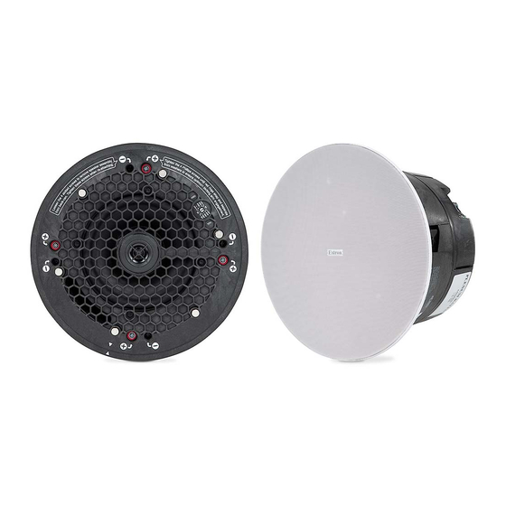
Summary of Contents for Extron electronics SF 26CT
- Page 1 User Guide Speakers SF 26CT Two way SoundField XD Ceiling Speakers with ® 8" Plastic Back Can 68-2223-01 Rev. A 12 16...
-
Page 2: Safety Instructions
Safety Instructions Safety Instructions • English Istruzioni di sicurezza • Italiano WARNING: This symbol, , when used on the product, is intended to AVVERTENZA: Il simbolo, , se usato sul prodotto, serve ad alert the user of the presence of uninsulated dangerous voltage within avvertire l’utente della presenza di tensione non isolata pericolosa the product’s enclosure that may present a risk of electric shock. - Page 3 ついては、 エクス トロンのウェブサイ ト より 『Extron Safety www.extron.com and Regulatory Compliance Guide』 (P/N 68-290-01) をご覧ください。 Copyright © 2016 Extron Electronics. All rights reserved. Trademarks All trademarks mentioned in this guide are the properties of their respective owners. ® The following registered trademarks(...
-
Page 4: Conventions Used In This Guide
FCC Class A Notice This equipment has been tested and found to comply with the limits for a Class A digital device, pursuant to part 15 of the FCC rules. The Class A limits provide reasonable protection against harmful interference when the equipment is operated in a commercial environment. This equipment generates, uses, and can radiate radio frequency energy and, if not installed and used in accordance with the instruction manual, may cause harmful interference to radio communications. -
Page 5: Table Of Contents
Configuring the Speaker ........18 Mounting the Speaker ........19 Reference Information ........22 Painting the Speaker Grille ........ 22 Troubleshooting ..........23 Testing Source Signal (all configurations) ..23 Testing the Impedance (Loop-Through Configuration Only) ........23 SF 26CT User Guide • Contents... - Page 6 SF 26CT User Guide • Contents...
-
Page 7: Introduction
UL 2043 listed composite speaker enclosure, the SF 26CT meets stringent UL requirements for smoke and heat release in plenum air spaces. The SF 26CT features a 6.5" woofer and 3/4" tweeter. Its coverage angle is 111°. It has a frequency range of 65 Hz to 20 kHz. -
Page 8: Application Example
Application Example The application diagram below shows one way to configure a system using the SF 26CT. Audio Extron Ethernet VoIP SF 26CT Full-Range Ceiling Speakers Conference Table Credenza Ethernet Extron Audio DMP 128 Plus C V Digital Matrix Processor... -
Page 9: Installation In A Suspended Ceiling (Single Installer)
Installation in a Suspended Ceiling (Single Installer) If a single installer is installing the SF 26CT speaker system, follow the steps in this section. Topics in this section include: • Installation Considerations • Preparing the Installation Location • Configuring the Speaker •... - Page 10 C-ring V-rail Figure 3. Positioning the C-ring assembly on the V-rails Secure the C-ring to the V-rails using two screws. Route the speaker wires through the ceiling tile hole. SF 26CT User Guide • Installation - Single Installer...
-
Page 11: Configuring The Speaker
Power Ampli er Speaker 1 Power Ampli er Speaker 2 Speaker 1 Wiring a Single Speaker SF 26CT User Guide • Installation - Single Installer Wire Gauge Table Wiring a Single Speaker Wire Gauge Table (Red) Number of Wires per... - Page 12 Using a cable clamp on the access plate: • Figure 5. Using a cable clamp Using a conduit adapter on the access plate: • Flexible Conduit Adapter Figure 6. Using a conduit adapter SF 26CT User Guide • Installation - Single Installer...
-
Page 13: Mounting The Speaker
NOTE: The screw hole locations are marked on the Locking arm front baffle with a Phillips-head screw symbol. screw hole marking Use these holes to tighten the locking arms. Figure 7. Clamping the speaker to the C-ring SF 26CT User Guide • Installation - Single Installer... - Page 14 Do not allow any slack in the secondary support line. • Ne laissez pas de mou au niveau du filin de sécurité secondaire. Replace the adjacent ceiling tile that was removed in step 4b on page 4. SF 26CT User Guide • Installation - Single Installer...
- Page 15 • le niveau d’impédance combinée ne soit pas équivalent à une valeur inférieure à l’impédance minimum de l’amplificateur. 8Ω Adjust the Tap Selector Figure 10. Setting the rotary tap selector switch SF 26CT User Guide • Installation - Single Installer...
- Page 16 Install the grille. Position the grille so that it covers the baffle of the speaker. Six small magnets secure the grille in place. Speaker Grille Figure 11. Installing the grille NOTE: Specific test points can be used to troubleshoot speaker system problems (see on page 23). Troubleshooting SF 26CT User Guide • Installation - Single Installer...
-
Page 17: Installation In A Suspended Ceiling (Division Of Labor)
NOTE: Notches are provided to help pry the speaker assembly from the back can. Figure 12. Unscrewing the speaker assembly from the back can SF 26CT User Guide • Installation in a Suspended Ceiling - Division of Labor... -
Page 18: Preparing The Installation Location
Preparing the Installation Location Follow the steps in Preparing the Installation Location on page 3. Configuring the Speaker Follow the steps in Configuring the Speaker on page 5. SF 26CT User Guide • Installation in a Suspended Ceiling - Division of Labor... -
Page 19: Mounting The Speaker
Clamp the speaker back can to the C-ring by using a Phillips screwdriver to tighten the four locking arms to the C-ring. Figure 15. Tightening the locking arms SF 26CT User Guide • Installation in a Suspended Ceiling - Division of Labor... - Page 20 Ne laissez pas de mou au niveau du filin de sécurité secondaire. Replace the adjacent ceiling tile that was removed in step 4b on page 4. Repeat steps 1 and 2 for each speaker being installed. SF 26CT User Guide • Installation in a Suspended Ceiling - Division of Labor...
- Page 21 Clamping the speaker to the C-ring ATTENTION: • To avoid damaging the speaker, do not overtighten the four screws. • Pour éviter d’endommager l’enceinte, ne serrez pas trop les quatre vis. SF 26CT User Guide • Installation in a Suspended Ceiling - Division of Labor...
- Page 22 équivalent à une valeur inférieure à l’impédance minimum de l’amplificateur. 8Ω Adjust the Tap Selector Figure 20. Setting the rotary tap selector switch SF 26CT User Guide • Installation in a Suspended Ceiling - Division of Labor...
- Page 23 Speaker Grille Figure 21. Installing the grille NOTE: Specific test points can be used to troubleshoot speaker system problems (see on page 23). Troubleshooting SF 26CT User Guide • Installation in a Suspended Ceiling - Division of Labor...
-
Page 24: Installation In A Hard Ceiling
Installation in a Hard Ceiling To install the SF 26CT in a hard ceiling (having no ceiling tiles), with the ceiling structure in place, follow the steps in this section. Topics in this section include: • Preparing the Installation Location •... -
Page 25: Mounting The Speaker
Clamp the speaker to the C-ring by using a Phillips screwdriver to tighten the four locking arms to the C-ring. Figure 24. Clamping the speaker to the C-ring SF 26CT User Guide • SF 26CT User Guide • Installation in a Hard Ceiling... - Page 26 Lors de la connexion de plusieurs enceintes en mode 8 ohm, assurez vous que • le niveau d’impédance combinée ne soit pas équivalent à une valeur inférieure à l’impédance minimum de l’amplificateur. SF 26CT User Guide • SF 26CT User Guide • Installation in a Hard Ceiling...
- Page 27 Speaker Grille Figure 27. Installing the grille NOTE: Specific test points can be used to troubleshoot speaker system problems (see on page 23). Troubleshooting SF 26CT User Guide • SF 26CT User Guide • Installation in a Hard Ceiling...
-
Page 28: Reference Information
Apply an even coat across the entire front surface. • Be sure not to clog the grille holes. Wait for the paint to dry. Reattach the scrim to the back of the grille. Reattach the grille to the speaker. SF 26CT User Guide • Reference Information... -
Page 29: Troubleshooting
To do this, connect to the outer (LOOP) terminals of the captive screw connector, as shown below. Red Wire (+) from Amplifier Amplifier To next speaker(s) Black Wire (-) from Amplifier Test Points Figure 30. Impedance Test Points — Loop-through Configuration Impedance Test Points SF 26CT User Guide • Reference Information... - Page 30 Extron Electronics makes no further warranties either expressed or implied with respect to the product and its quality, performance, merchantability, or fitness for any particular use. In no event will Extron Electronics be liable for direct, indirect, or consequential damages resulting from any defect in this product even if Extron Electronics has been advised of such damage.
Need help?
Do you have a question about the SF 26CT and is the answer not in the manual?
Questions and answers