Advertisement
Quick Links
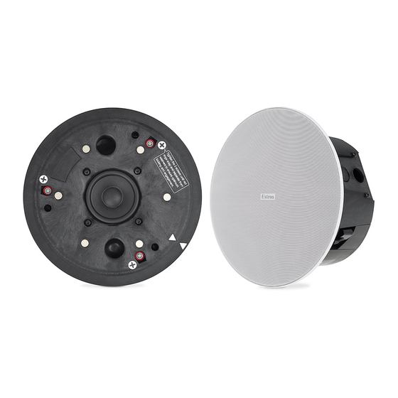
SF 3C LP and SF 3CT LP • Setup Guide
This setup guide contains installation information about the SF 3C LP and SF 3CT LP full range speakers. These speakers can be
installed by a single trade installation procedure or by a multi trade installation procedure. The entire assembly is plenum rated.
WARNING:
Potential risk of severe injury. Installation and service must be performed by authorized personnel only.
AVERTISSEMENT :
par le personnel autorisé uniquement.
NOTE: Installation of conduit and conduit adapters must conform to all applicable building codes and local ordinances.
Installing the SF 3C LP or SF 3CT LP in
a Suspended Ceiling
For hard ceiling installations, see the SF 3C LP and
SF 3CT LP User Guide.
Remove power from all devices.
1.
NOTE: If the grille is to be painted, see the user
guide for more information.
Cut a hole for the SF 3C LP or SF 3CT LP. Use the
2.
provided cutout template to outline the hole to be cut in
the ceiling tile, as described below.
Remove the ceiling tile, and draw diagonal lines
a.
across it from opposite corners to locate its center.
Mark the intersection where the lines cross.
Position the center hole of the cutout template
b.
directly over the center of the tile, marked in
step 2a.
Trace a circle on the ceiling tile around the cutout
c.
template.
Cut out the circle traced in the ceiling tile.
d.
Replace the ceiling tile in the ceiling.
e.
Attach two V-rails and one C-ring above the hole cut
3.
in step 2, as described below.
Assemble two V-rail half sections so that they
a.
become one single piece by fitting the tab of
one end into the slot of the other end. Open the
V-rail until it locks together, as shown. Repeat this
procedure for the other V-rail.
Risque potentiel de blessure grave ou de mort. L'installation et l'entretien doivent être effectués
Remove a ceiling tile adjacent to the tile with the
b.
hole.
Place both assembled V-rails on the cut ceiling tile
c.
and position them equally on either side of the hole.
The ends of the V-rails go over the ceiling grid.
Position the C-ring assembly on the two V-rails so
d.
that the C-ring is centered over the hole.
V-rail
Secure the C-ring to the V-rails using two screws.
e.
Route the speaker wires through the ceiling tile hole.
4.
Configure the terminal cover and captive screw
5.
connector, as described below.
The terminal cover has one alternate hole available
a.
covered by a knockout. This hole may be used for
loop out when using conduit. If this knockout needs
to be removed, do the following:
With the terminal cover still attached to the
i.
speaker, place the tip of a flat-head screwdriver
against the notch of the knockout.
Lightly tap the screwdriver with a hammer to
ii.
remove the knockout.
C-ring
1
Advertisement

Related Manuals for Extron electronics SF 3C LP


Summary of Contents for Extron electronics SF 3C LP
- Page 1 SF 3C LP and SF 3CT LP • Setup Guide This setup guide contains installation information about the SF 3C LP and SF 3CT LP full range speakers. These speakers can be installed by a single trade installation procedure or by a multi trade installation procedure. The entire assembly is plenum rated.
- Page 2 SF 3C LP and SF 3CT LP • Setup Guide (Continued) Loosen the two side terminal cover screws and ATTENTION: remove the cover. • Do not tin the wire leads before installing into the connector. Tinned wires are not Remove the as secure in the connector and could be terminal cover.
- Page 3 Replace the terminal cover and tighten the two retaining screws. NOTE: The terminal cover can be positioned in one of two ways depending on the application. Flip the cover to the desired position with the wire openings either on the side or on the top of the speaker enclosure before tightening the screws.
- Page 4 Extron USA - East +1.714.491.1500 +1.919.850.1000 +31.33.453.4040 +91.80.3055.3777 +1.714.491.1517 FAX +1.919.850.1001 FAX +31.33.453.4050 FAX +91.80.3055.3737 FAX www.extron.com © 2016 Extron Electronics — All rights reserved. All trademarks mentioned are the property of their respective owners. 68-2224-50 Rev. B 06 16...
Need help?
Do you have a question about the SF 3C LP and is the answer not in the manual?
Questions and answers