Table of Contents
Advertisement
Quick Links
User's Manual
1
Power down
Power down all attached devices before proceeding.
2
Suspended ceiling installation
Remove the ceiling tile where the FF 120T speaker will be
installed. Cut out a 12" section of the tile from either end
where the speaker will be installed, as shown below.
End Section
12"
2'
4'
Draw Lines
24" x 48" Ceiling Tile
3
Remove the terminal cover plate
Loosen the two screws (do not remove) on the top terminal
cover plate and remove the cover plate.
• If a 70 V/100 V line distribution amplifier is being used,
such as the Extron XPA 2001-70V or XPA 2001-100V, the
cover plate is no longer needed since the included CPX 120
transformer cover plate will be installed in its place.
• If the 70 V/100 V line distribution system is not being
installed, retain the cover plate and proceed to step 6b.
4
Routing cables through the
CPX 120 cover plate
The CPX 120 cover plates mount to the speakers with
the transformer side down. See the illustration below.
Flexible
From Amp
Flexible Conduit
Conduit
Adapter
or
or
Seismic Anchor
Ring
Top Terminal
Cover
N Installation of conduit and conduit adapters should
conform to all applicable building codes and local
ordinances.
68-1450-02 Rev. A
07 09
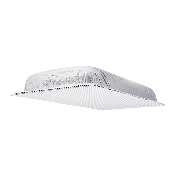
Flat Field Speaker
Cut Material
12"
2'
2'
24" x 24" Ceiling Tile
To Second Speaker
Cable Clamp
Adapter (supplied)
Locking Ring
See the NOTES below.
Get other manuals https://www.bkmanuals.com
FF 120T
5
Connecting wires to the CPX 120
terminal block
The transformer side of the CPX 120 cover plate has a
7-connector terminal block. Route the two wires from the
amplifier through the cover plate hole to the transformer side.
The black negative (-) wire attaches to the "COM" terminal,
and the red postitive (+) wire attaches to the desired terminal
tap.
COM
16 W
COM
NC
N Installation in a plenum-rated environment
requires a wire gauge of 12 AWG to 18 AWG.
Pull the speaker wires from the conduit if a conduit is used.
Strip 3/16" (5 mm) from the wire ends, keep the wire end
strands together by twisting them (do not tin the wires), and
secure the wires to the appropriate taps on the terminal
block's captive screw connectors as indicated on the tap
label. Use a small flat blade screwdriver to tighten the
terminal block screws. See the note below for wiring
additional speakers.
N Route the speaker wires from the second speaker
through the cover plate hole to the transformer
side and twist the black negative (-) wires together
and twist the red positive (+) wires together before
inserting them into the terminal block. Additional
speakers can be daisy chained this way.
N Be sure to observe the 70 V or 100 V system
designation as indicated on the label.
N Wiring two speakers in parallel requires that the
maximum wire gauge not exceed 16 AWG. In a
single speaker installation the wire gauge should
not exceed 12 AWG.
When using flexible conduit, insert the conduit into the cover
plate opening using an appropriate conduit adapter and
secure the conduit to the plate as shown in the following
illustration.
1 W
8 W
4 W
2 W
NC
16 W
8 W
4 W
2 W
1 W
1
Advertisement
Table of Contents

Related Manuals for Extron electronics FF 120T


Summary of Contents for Extron electronics FF 120T
- Page 1 7-connector terminal block. Route the two wires from the amplifier through the cover plate hole to the transformer side. Remove the ceiling tile where the FF 120T speaker will be The black negative (-) wire attaches to the “COM” terminal, installed.
- Page 2 FF 120T Flat Field Speaker User’s Manual Connecting wires from a low impedance amplifier to the speaker (Black) To Speaker (-) Terminal Route the wires from the amplifier to the speaker using the (Red) To Speaker same procedure for routing speaker wire (and conduit if (+) Terminal applicable) through the cover plate as described in step 3.
- Page 3 FF 120T Flat Field Speaker User’s Manual Installing the speaker in the Anchor this end to a suitable secure point. ceiling Route the cable through the seismic anchor ring See the following illustration. and bendout tab. a. Replace the cover plate and tighten the two cover screws.
- Page 4 Regulatory compliance Safety ........ NFPA90A, NFPA70; CPX 120 Transformer Cover Plates (2) UL Listed for use in plenum airspaces meets FF 120T Setup UL 2043 for heat and smoke release, meets Guide UL 1480 for commercial and professional audio systems Warranty ........
Need help?
Do you have a question about the FF 120T and is the answer not in the manual?
Questions and answers