
Related Manuals for Sony PDW-HD1200


Summary of Contents for Sony PDW-HD1200
- Page 1 PROFESSIONAL DISC RECORDER PDW-HD1200 OPERATION MANUAL [English] 1st Edition (Revised 1)
-
Page 2: Important Safety Instructions
This apparatus is provided with a main switch on the rear Important Safety Instructions panel. Install this apparatus so that user can access the main switch • Read these instructions. easily. • Keep these instructions. • Heed all warnings. • Follow all instructions. •... - Page 3 CAUTION The use of optical instruments with this product will increase eye hazard. CAUTION Use of controls or adjustments or performance of procedures other than those specified herein may result in hazardous radiation exposure. This Professional Disc Recorder is classified as a CLASS 1 WARNING LASER PRODUCT.
- Page 4 Electromagnetic Environments: E1 (residential), E2 (commercial and light industrial), E3 (urban outdoors), E4 (controlled EMC environment, ex. TV studio). The manufacturer of this product is Sony Corporation, 1-7-1 Konan, Minato-ku, Tokyo, 108-0075 Japan. The Authorized Representative for EMC and product safety is Sony Deutschland GmbH, Hedelfinger Strasse 61, 70327 Stuttgart, Germany.
-
Page 5: Table Of Contents
Table of Contents Chapter 1 Overview Features..................10 Features of this unit ................10 System Configurations ..............13 Chapter 2 Names and Functions of Parts Front Panel..................14 Display window ................... 19 Rear Panel ..................24 Chapter 3 Preparations Preparing Power Sources............. 27 Supplying power.................. - Page 6 Loading and unloading a disc.............. 48 Formatting a disc ................. 48 Chapter 4 Recording and Playback Recording ..................49 Mixed recording of clips in different formats on the same disc..49 Preparations for recording ..............49 Carrying out recording ................ 50 Continuing recording while exchanging discs (disc exchange cache function)..................
- Page 7 Managing clip lists................83 Disc Operations ................85 Checking disc properties..............85 Using planning metadata ..............85 Checking user-defined essence marks ..........87 Formatting discs................... 87 Displaying disc and clip properties in a web browser ......88 Transferring Clips (Direct FTP Function) ........90 Preparations for clip transfers..............
- Page 8 Items in the extended menu............... 121 Extended menu operations ..............134 Maintenance Menu............... 136 Items in the maintenance menu ............136 Maintenance menu operations............139 Chapter 8 Planning Metadata Overview..................142 Manipulating planning metadata ............142 Setting clip names by using planning metadata ........ 142 Setting essence mark names by using planning metadata ....
- Page 9 Glossary ..................172 Index .................... 174 Table of Contents...
-
Page 10: Features
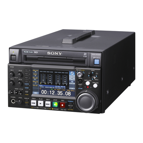
8-channel audio recording at high sound quality. 1) MPEG HD422 is a trademark of Sony Corporation. Long recording times The PDW-HD1200 (referred to as “this unit”) is a PDW-HD1200 supports dual-layer Professional Discs (50 professional disc recorder supporting full HD (1920 ×... - Page 11 Lists of these marks can be displayed on the color LCD or an 1) HDCAM is a trademark of Sony Corporation. external monitor, allowing you to quickly find scenes Clip Continuous Rec function that were marked for later reference.
-
Page 12: Usability Features
Sony Professional products web site. Sony Professional products and solutions site homepage: IT friendly U.S.A. -
Page 13: System Configurations
System Configurations Professional Discs ANALOG AUDIO OUTPUT/INPUT • PFD23A • PFD50DLA PDW-700 PDW-1500 Sony BP-L80S/GL95 battery HDSDI SDSDI INPUT OUTPUT RM-280 editing BKP-L551 battery REMOTE controller EJECT adaptor REMOTE (9P) PUSH SET(S.SEL) MARK1 ACCESS CH-1 CH-3 MENU MARK2 SHTL/JOG ALL CH... -
Page 14: Front Panel
Names and Functions of Parts Chapter Front Panel The names and symbols of buttons and knobs on the front Orange: Function when the button is operated with the panel are color coded according to function. SHIFT button held down. White: Function when the button or knob is operated Blue: Function related to thumbnail operations. - Page 15 1 Audio level adjustment section access to the disc is completed before the unit switches to the standby state. 1 CH-1/ALL CH, CH-2 to CH-4 adjustment knobs Note CH-1 CH-3 While the ACCESS indicator is lit, do not turn off the POWER switch on the rear panel or disconnect the power ALL CH cord.
- Page 16 For details of playback operations with these buttons and dials, see “Playback operation” on page 56. 1 V/MARK1 button and v/MARK2 button 2 IN indicator and OUT indicator a SHTL/JOG button Press this button, turning it on, to perform shuttle playback MARK1 with the shuttle dial or jog playback with the jog dial.
-
Page 17: Menu Button
c PUSH SET(S.SEL) knob menu item 101 SELECTION FOR SEARCH DIAL ENABLE to “dial”). Use for menu and GUI screen operations. Turn the knob to select items, and press it to confirm the selection. This button is also used to set numerical and timecode values. Note You can also change the playback speed by pressing the When setup menu item 101 SELECTION FOR SEARCH... -
Page 18: Display Button
pictures of the first frames. This can also be used to cue up appear. Press once more, turning the indicator off, to return to a whole-screen display. long clips. To display the thumbnails of essence mark frames (frames This button also becomes a function button (F5) when the with an essence mark attached), hold down the SHIFT function menu is visible. -
Page 19: Display Window
1) When setup menu item 153 FIND MODE is set to “clip & rec start mark”, To stop recording, press the STOP button. this button jumps to the frame where the next Rec Start essence mark is set and displays the video of that frame. To monitor in E-E mode You can press this button from stop mode to monitor input d STOP button... - Page 20 a Audio input display/Audio level meters mode, which can be switched over using AU METER on Displays information about audio. There are two display page P4 AUDIO of the function menu. modes for the audio level meter: FULL mode and FINE Meter display mode: FULL Meter display mode: FINE A Input signal display...
- Page 21 B REC RUN/FREE RUN: Displays the timecode run mode. The run mode is set with RUN MODE on page All remaining clips or clip list playback time P5 TC of the function menu (see page 45). Total number of clips recorded on disc C Timecode generator mode: Displays the timecode source and generation method (preset or regenerate).
- Page 22 Blue: Disc capable of recording and playback. Display Description Yellow: Disc capable of playback only. Red: Disc incapable of recording and playback. BANK1 The current menu settings are the same as the settings in menu bank 1. BANK2 The current menu settings are the same Note as the settings in menu bank 2.
- Page 23 when the signals are synchronized but their phases do not D Low battery warning: Appears and flashes during match. operation with a battery pack when the battery power is almost exhausted. i Video input display E Converter display: Displays the current down- or up- converter mode, depending on the state of the unit.
-
Page 24: Rear Panel
Rear Panel 1 Power supply section (see 7 DC IN 12V connector page 25) 8 REMOTE connector 2 Analog audio signal input/ output section (see page 25) 9 COMPOSITE OUTPUT1, 2 1 HDMI OUT connector (SUPER) connectors 2 SD/HDSDI INPUT connector 0 REF.VIDEO INPUT connectors 3 Timecode input/output... - Page 25 2 - AC IN connector (D-sub 9-pin) To control this unit from a controller or VTR supporting the RS-422A Sony 9-pin VTR protocol, connect the device to this connector. g DC IN 12V connector (XLR 4-pin, male) Connect to a DC power source of 12 V.
- Page 26 a ANALOG AUDIO INPUT 1, 2 connectors (XLR 3- 3 Timecode input/output section pin, female) These input analog audio signals. With A1 INPUT or A2 INPUT on page P2 AUDIO, and 1 TIME CODE IN connector A3 INPUT or A4 INPUT on page P3 AUDIO of the 2 TIME CODE OUT function menu (see page 45), you can select whether the connector...
-
Page 27: Preparing Power Sources
Refer to the operating battery pack. instructions for your battery charger for more For safety, use only the Sony battery packs listed below. information about how to charge the batteries. Lithium-ion battery pack: BP-L80S, BP-GL95 •... -
Page 28: Initial Setup
Initial Setup This unit is shipped with the system frequency, recording format, and current date and time still unset. Therefore, you need to make initial setup settings before using the unit. (You cannot use the unit without setting it BP-GL95 up.) Once the unit has been set up, the settings are retained even Slide the BP-GL95 as shown below so that the... - Page 29 RETURN I NIT IA L S ETU P Pu sh F5 (SA VE ) K ey! ! C AN CEL &PR EV : F 1( RET ) S AV E&R EBO OT : F 5( SET ) INIT The message “NOW SAVING...” appears again, and Display the recording format that you want to use, and the setting screen disappears.
-
Page 30: Front Panel Tilt Mechanism
To change the angle of the front panel Front Panel Tilt To change the angle to position 2 from position 1, pull the front panel out to position 2. Mechanism To change the angle to position 1 from position 2, first unlock the front panel by pulling it all the way out to the return position. -
Page 31: Connections And Settings
Connecting three PDW-HD1200 units to a laptop Connections and computer via a LAN Settings PDW-HD1200 Note Laptop computer Production of some of the peripherals and related devices described in this chapter has been discontinued. For advice about choosing devices, please contact your Sony dealer or a Sony sales representative. -
Page 32: Connections For Cut Editing
Use of a shielded cable is recommended. PDW-HD1200 (this unit) Laptop computer To S400 connector i.LINK cable (not supplied) Connections for cut editing The following figure shows a cut editing system comprising this unit as a player. When making the connections, also refer to the manuals provided with the equipment to be connected. - Page 33 1: 75Ω coaxial cable (not supplied) HD video monitor 2: 9-pin remote control cable (not supplied) To HDSDI input connector HDSDI OUTPUT 2 (SUPER) PDW-HD1200 (this unit, player) REMOTE ANALOG AUDIO INPUT ANALOG AUDIO OUTPUT AUDIO MONITOR REF.VIDEO INPUT Reference video signal REF.VIDEO...
- Page 34 29.97P 50i/25P Using RM-280 The following figure shows a cut editing system comprising a PDW-HD1200 as a player, a PDW-F1600 unit as a recorder, and an RM-280 as an editing controller. 1: 75Ω coaxial cable (not supplied) HD video monitor...
-
Page 35: Using The Editing Functions Of The Recorder (Controlling Through Remote(9P) Connector)
PDW-F1600 (recorder) settings RM-280 (editing controller) settings PDW-HD1200 (player) settings Function menu pages P2 and P3 AUDIO Setup menu 06 SYNC VTR: Setup menu item 214 REMOTE >A1 to A8 INPUT: SDI RECORDER INTERFACE: 9PIN Function menu page P5 TC >TCG: INT Setup menu 09 EDIT DLY: –7... -
Page 36: Connections For Pool Coverage
For details of HDW-M2000/M2000P settings, refer to the HDW-M2000/M2000P Operation Manual. Connections for pool coverage The following figure shows an example of connections for pool coverage, with the PDW-700 Professional Disc Camcorder connected. PDW-HD1200 (this PDW-700 unit) To SDI OUT 1 connector To SD/HDSDI INPUT connector 75Ω... -
Page 37: Synchronization Reference Signals
Synchronization Reference Signals The synchronization reference signal generator of this unit setting of OUT REF on page P6 REF of the function menu, synchronizes to a reference signal input to the REF. and on the type of the selected input signal. Video output VIDEO INPUT connector or to a video input signal. -
Page 38: Setting System Frequency
Setting System Setting Timecode Frequency There are the following four ways of recording timecode: Internal Preset mode: This records the output of the This unit can record and play back video at the system internal timecode generator, set beforehand to an frequencies of 59.94i or 50i. - Page 39 out steps 2 to 5. Settings are made in hexadecimal (0-9, The first digit of the time data display starts flashing. A-F). You can record ID codes in user bits. To record timecode that follows sequentially upon the last recorded timecode (Internal Regen) You can record timecode so that it is continuous from one clip to the next on the disc.
-
Page 40: Superimposed Text Information
Make the following settings on page P5 TC of the Superimposed Text function menu. • Set TCG to “SDI”. Information • Set PRST/RGN to “TC”. Executing either of these procedures starts the internal The video signal output from the COMPOSITE OUTPUT timecode generator running in synchronization with the 2 (SUPER) connector, SDSDI OUTPUT 2 (SUPER) external timecode generator. -
Page 41: Operation Mode
a Type of time data Display Operation mode Display Meaning Block A Block B Counter data C.STANDBY OFF Standby off mode TC reader timecode STOP Stop mode TC reader user bits data C.STOP Stop mode TCR. VITC reader timecode NEXT xxx Cuing up to the first frame of the UBR. - Page 42 To prevent playback conditions from Display Name Description deteriorating Red condition The playback condition has Pay attention to the following points when handling discs. deteriorated. There are no read • Do not open disc cartridges and touch discs directly with errors, but you should take the your hands.
-
Page 43: Basic Operations Of The Function Menu
button again while the page P2 is displayed switches the Basic Operations of the page to P8. To clear the function menu from the screen Function Menu Press the DISPLAY button to switch to the video monitor display. The function menu provides access to frequently used To change the setting of a function menu settings, such as input video signal selection and timecode item... -
Page 44: P1 Video Page
Item Setting Item Setting F4: CNTR SEL Selects the type of time data to display in F5: HUE/CHRM Sets the hue (chroma phase). the time data display area. PRESET: Set the hue (chroma phase) to TC: Timecode a preset value, regardless of manual COUNTER: Elapsed recording or setting. -
Page 45: P4 Audio Page
P4 AUDIO page Item Setting F6: LEVEL MT Specifies the position at which to Item Setting superimpose audio level meters in the F1: A5 VOL video monitor screen (in full-screen Sets the volume of audio channel 5. display mode). The volume can be adjusted within the OFF: Do not superimpose. -
Page 46: P6 Ref Page
Item Setting Item Setting F2: PRST/RGN Selects the following for the internal F6: FINE Makes fine adjustment to the sync phase timecode generator. of HD output signals. While the setting PRESET: Presets an initial value for the value is flashing, turn the PUSH timecode generated by the internal SET(S.SEL) knob to adjust the sync timecode generator, as specified... -
Page 47: Handling Discs
• PFD23A (capacity 23.3 GB) page 136). • PFD50DLA (capacity 50.0 GB) • “DISABLE” is always selected when the unit is powered off and then on 1) Professional Disc is a trademark of Sony Corporation. again, regardless of the previous setting. Notes F5:–... -
Page 48: Write-Protecting Discs
• If condensation forms, allow ample time to dry before MODE KEY ENABLE DURING RECORDING to use. “stop”. Write-protecting discs Formatting a disc To protect the content recorded on the disc from accidental Unused discs are formatted automatically when they are erasure, move the Write Inhibit tab on the lower surface of loaded into this unit. -
Page 49: Chapter 4 Recording And Playback
Recording and Playback Chapter Frame frequency groups Recording The system frequencies supported by this unit are divided into frame frequency groups, as shown in the following table. This section describes video and audio recording on the Frame frequency group System frequency unit. -
Page 50: Carrying Out Recording
If the disc becomes full Selection of audio channels to monitor: Select with MONITR R and MONITR L on page P2 AUDIO of Recording stops and the message “ALARM DISC END.” the function menu. appears on the monitor. Volume adjustment of the monitor audio: Adjust with the LEVEL knob. -
Page 51: Continuing Recording While Exchanging Discs (Disc Exchange Cache Function)
If the unit is set up to display superimposed text inserted, it copies the data from the cache to the disc information (see page 40), “SHOTMARK*” (*: 0 to 9) and resumes normal recording. appears every time you set an essence mark. When Shot Mark0 to Shot Mark9 is set, you can search for Disc exchange cache indications and their the shot marks by displaying thumbnails of the frames at... -
Page 52: Recording With The Hdsdi Remote Control Function
Exchanging discs Recording with the HDSDI remote Even during recording, it is possible to eject discs by control function pressing the EJECT button on the front panel. After a disc is exchanged, the unit resumes operation according to the This section explains the settings required for recording in embedded REC or STOP command. -
Page 53: Using The Live Logging Function
It is not possible to preset the for a disc and you use another XDCAM system other timecode to be recorded. than the PDW-HD1200 to perform a full salvage of the • The Disc Exchange Cache function and Clip Continuous disc, use the PDW-F1600, PDW-HD1500, PDW-HR1, Rec function cannot be enabled in Live View mode. - Page 54 HOME page of the function menu is set to “ON”, set Code (XXXX) Model it to “OFF” (see page 43). • This operation cannot be cancelled once it begins. 0002 PDW-1500/530/510/R1 PDW-F70/F350/F330 Press the PUSH SET(S.SEL) knob. 0200 PDW-F70/F350/F330 (Version 1.9 or higher) Processing begins and the message “Executing.”...
-
Page 55: Playback
After recording Playback The unit stops at the position where recording ended. To play back a clip, press the PREV button to move to the start frame of any clip or press the PREV button with the PLAY button held down to move to any position. This section describes playback of video and audio on the unit. -
Page 56: Playback Operation
To jump to the next or previous clip, then start after the initial frame. The setting range is 0 seconds to 10 seconds. playback Use the PREV button, NEXT button, jog dial, or shuttle dial. Playback operation To stop playback Press the STOP button. - Page 57 To stop playback in shuttle mode, return the shuttle dial to the center position, or press the STOP button. EJECT When setup menu item 101 SELECTION FOR SEARCH DIAL ENABLE is set to “dial” (factory PUSH SET(S.SEL) MARK1 ACCESS CH-1 CH-3 default setting), you can start shuttle playback by MENU...
-
Page 58: Playback Operations Using Thumbnails
This allows you to perform repeat playback, limited to variable playback in the forward direction in the range 0 to +1 times normal speed. To perform manual frame sync playback During playback, you can adjust the playback output phase in units of one frame. To do so, hold down the PLAY button and turn the PUSH SET(S.SEL) knob in either direction. -
Page 59: Chapter 5 Operations In Gui Screens
Operations in GUI Screens Chapter Overview You can perform scene searches, play the searched scenes, (The GUI screens can display European languages, and select scenes (edit clip list) in Graphical User Interface Korean, Simplified Chinese, and Traditional Chinese for (GUI) screens. The GUI screens are your gateways to discs clip names and titles.) and the data saved on discs. -
Page 60: Information And Controls In Thumbnail Screens
Clip thumbnail screen Clip playback screen Clip:C0006 006/040 TC 00:23:00:25 TC 00:23:40:07 TC 00:24:45:11 TC 00:25:06:14 TC 00:25:49:23 TC 00:26:22:10 TC 00:27:19:04 TC 00:27:51:09 TCR 00 : 23 : 00 . 26 TC 00:28:06:09 TC 00:28:22:02 TC 00:23:34:18 TC 00:23:54:22 STILL 30 NOV 2005 13:38 0:00:10:23... - Page 61 g Duration Clip thumbnail screen Displays the duration (recording time) of the selected clip. This screen displays thumbnails of clips on the disc in the When multiple clips are selected, displays the total order that they were recorded. You can use this screen to recording time of the selected clips.
- Page 62 Clip list thumbnail screen This screen displays thumbnails of the clips in the current clip list. You can use this screen to create and edit clips Expand Clip 008/024 x 12 001/012 lists. TC 00:01:35:17 TC 00:01:38:00 TC 00:01:36:14 TC 00:01:36:27 Clip List:E0001 002/013 TC 00:01:37:11...
-
Page 63: Displaying Menus
Chapter of Clip 001/024 001/003 Shot Mark1 001/029 TC 00:23:00:25 TC 00:23:02:00 TC 00:23:04:00 TC 00:23:02:00 TC 00:24:45:25 TC 00:25:07:01 TC 00:25:40:24 TC 00:26:22:11 TC 00:27:19:25 TC 00:27:51:25 TC 00:28:06:17 TC 00:28:35:00 TC 00:28:55:02 TC 00:29:10:05 TC 00:29:20:03 C0001 0:00:01:05 30 NOV 2006 19:55 "Capping literally years of spe..."... -
Page 64: Disc Menu
To display the Thumbnail Menu Clip thumbnail screen To display the Thumbnail Menu, press the MENU button with a thumbnail screen displayed. To return to the original screen, press the MENU button again, or press the RESET/ RETURN button. EJECT MARK1 PUSH SET(S.SEL) ACCESS... - Page 65 Item Operation/Setting Planning Metadata Properties Display the properties of the currently loaded planning metadata. Planning Clip Name Suffix Change the serial number added to clip names created by using planning metadata. Clear Planning Metadata Clear the currently loaded planning metadata from the unit’s memory. Lock or Delete All Clips Sub-Item Lock All Clips...
-
Page 66: Gui Screen Operations
To return to the original screen, press the RESET/ GUI screen operations RETURN button. EJECT EJECT PUSH SET(S.SEL) MARK1 ACCESS PUSH SET(S.SEL) MARK1 ACCESS CH-1 CH-3 CH-1 CH-3 MENU MARK2 MENU MARK2 SHTL/JOG SHTL/JOG ALL CH VAR/JOG ALL CH VAR/JOG CH-2 CH-4 CH-2... -
Page 67: Thumbnail Operations
To scroll hidden parts of the string into Thumbnail Operations view When a b or B mark is displayed for an item, you can press the B/IN or b/OUT button to scroll the display by You can use thumbnail screens to display clip information one character for each press. -
Page 68: Searching With Thumbnails
Press the PUSH SET(S.SEL) knob at the new position. first frame in each block. This is a quick and efficient way to review the selected clip and search for target scenes. The thumbnail at the position indicated in the small You can specify 12, 144, or 1728 divisions. - Page 69 See “To set shot marks” (page 50) for more information. Display the Thumbnail Menu. See page 66 for more information about thumbnail screen Select Move Essence Mark. operations. The Move Essence Mark screen is displayed. In the clip thumbnail screen, select the thumbnail of a clip with chapters set.
-
Page 70: Playing The Scene You Have Found
To search for a thumbnail position and cue If planning metadata with user-defined essence mark has been loaded it up You can select user-defined essence marks (see page 87). See page 66 for more information about GUI screen operations. Select the thumbnail that you want to cue up. Clip:C0010 010/041 TC 00:23:00:25... - Page 71 • Select clips in a certain video format from a disc that contains clips in different video formats. • Select clips that have been set “NG” as a clip flag, and delete all of those clips in one operation. • Select only clips that have been recorded on the basis of a specified planning metadata entry, and transfer those clips to an external device using the Direct FTP function (see page 90).
-
Page 72: Selecting The Information Displayed On Thumbnails
Sequence Number: Thumbnail sequence number Item name Function Return to Upper Menu: Returns to the Thumbnail Lock or Delete All Filtered Unlock all of the filtered clips. Menu Clips >Unlock All Filtered Clips The selected information will appear at the bottom of Lock or Delete All Filtered Delete all of the filtered clips. -
Page 73: Checking Clip Properties
To select index pictures by using the expand and chapter functions After using the expand function (see page 68) or chapter function (see page 68) to find a frame, you can set that frame as the index picture of the clip. The following example explains how to do so from the expand thumbnail screen. - Page 74 To enter text using a USB keyboard or USB • Some symbols cannot be used in clip names. The keys for those symbols are disabled when you are editing a mouse clip name. You can connect a Windows USB keyboard or a Windows USB mouse to the MAINTENANCE connector (see See page 66 for more information about GUI screen...
-
Page 75: Setting Clip Flags
To exit the software keyboard from a USB keyboard With the cursor in an edit box, press the Enter key to move the focus to OK. Do one of the following. To confirm the edit and then exit the software keyboard: While OK is selected, press the Enter key. -
Page 76: Locking (Write-Protecting) Clips
To unlock a specific clip You can also use CLIP FLG on page P7 OTHER of the function menu to set and clear clip flags (see page 46). See page 66 for more information about thumbnail screen operations. Locking (write-protecting) clips In the clip thumbnail screen, select the thumbnail of the clip that you want to unlock. - Page 77 • If a deletion target clips is referenced by clip lists on the A message appears asking you to confirm that you disc, all of those clip lists are deleted as well. want to delete all clips. • If a deletion target clip is referenced in the current clip list, only those referencing sub clips are deleted at the Select OK to execute the deletion, or Cancel to cancel same time as the deletion target clip.
-
Page 78: Scene Selection (Clip List Editing)
Sub clips (clips in clip lists) Scene Selection (Clip List Clips (or parts of clips) that have been added to a clip list are called “sub clips”. Sub clips are virtual editing data that Editing) specify ranges in the original clips. You can use them without modifying the original data. -
Page 79: Creating And Editing Clip Lists
To add sub clips To play a clip list, insert a disc into the unit, load the clip list that you want to play, and press the PLAY button. You can add sub clips to clip lists from with the clip Clips are played according to the data in the clip list. - Page 80 To check the addition results the location where the currently selected sub clips will Move the cursor. be inserted. Press the RESET/RETURN button. To display the total duration after addition of the selected clips This returns you to the Clip thumbnail screen. Press the SHIFT button.
- Page 81 To delete the In point or Out point Save the clip list (see page 83). Press the RESET/RETURN button with the B/IN or b/OUT button held down. To adjust the In and Out points of sub clips (trim) With the SHIFT button held down, press the PUSH SET(S.SEL) knob.
- Page 82 To play using the clip list playback screen To cancel the In point or Out point setting Display the Thumbnail Menu, select Reset Inpoint or Reset Outpoint, and then press the PUSH SET(S.SEL) Display the clip list playback screen. knob. Press the PREV button or the NEXT button to display The In point or Out point setting returns to the previous the sub clip that you want to play.
-
Page 83: Managing Clip Lists
To preset the frequently used timecode Select the desired clip list name, and then press the Select Save Preset TC in the Thumbnail Menu, and PUSH SET(S.SEL) knob. then press the PUSH SET(S.SEL) knob. To save under the same name The timecode set in steps 4 and 5 is saved as a preset The following procedure saves the current clip list under value. - Page 84 Select the desired clip list, and then press the PUSH SET(S.SEL) knob. The name of the clip list selected here appears in the clip list thumbnail screen. When you execute the Save Delete Clip List E0001 Clip List command in the Disc Menu, the clip list will Delete this Clip List? be saved under that name.
-
Page 85: Disc Operations
Using planning metadata Disc Operations Planning metadata is a file that contains metadata about the clips to be shot and recorded. To use planning metadata, you will need to save a file in Checking disc properties advance in the specified location of a media, and insert the media into this unit. - Page 86 Select the desired planning metadata file, and then To scroll hidden parts of the string into view press the PUSH SET(S.SEL) knob. When a b or B mark is displayed for an item, you can press the B/IN or b/OUT button to scroll the display The selected planning metadata file is loaded into the by one character for each press.
-
Page 87: Checking User-Defined Essence Marks
Select Clear Planning Metadata, and then press the PUSH SET(S.SEL) knob. A message appears asking if you are sure that you want to clear the planning metadata. Select OK, and then press the PUSH SET(S.SEL) knob. The planning metadata is cleared from this unit’s memory. -
Page 88: Displaying Disc And Clip Properties In A Web Browser
The user name and password are set to the following when the unit is shipped from the factory. • User name: admin • Password: Model name (“pdw-hd1200”) After the user name and password are verified, an XDCAM web page appears. - Page 89 FTP download limitations The following limitations apply to FTP download operations. They do not apply to HTTP download operations. • The characters that can be used in the names of clip- related data files are single-byte letters, numbers, and symbols. However, the following symbols cannot be used.
-
Page 90: Transferring Clips (Direct Ftp Function)
Multiple clips with clip list Part of one clip partial put Upload clip (put) Download clip (get) PDW-HD1200 Network Laptop computer Local host (this unit) a) The following software requirements must be satisfied. • An FTP server function must be available. -
Page 91: Uploading Clips
XDCAM devices support UPnP. To transfer while preserving the UMID of the • PDW-F1600 transfer source clips • PDW-HD1500 Check the “UMID Unchanged” option. • PDW-HD1200 • PDW-HR1 Note • PDW-F800 If the remote host is a computer, clips are transferred • PDW-700 with the UMID unchanged regardless of this setting. - Page 92 prompting you to enable it. Select “OK” and then press Item Setting the PUSH SET(S.SEL) knob. The UPnP function will be enabled when you power the unit off and then on Host Name Host name or IP address. (If this is a host name, a DNS server must be again.) available on the connected network.
- Page 93 To check the connection on the remote host side If the remote host is an XDCAM device, check that the “NETWORK!” has appeared in the display or other status display location. The following table lists the various stages that appear in the connection status screen and describes the corresponding processing.
-
Page 94: Downloading Clips
See page 66 for information about thumbnail screen operations. Display the Disc Menu. Select Download Clip via Direct FTP, and then press the PUSH SET(S.SEL) knob. The Select Remote Host screen of the Download Clip via Direct FTP command appears. To upload part of a clip You can select part of a clip in the expand thumbnail screen or the chapter thumbnail screen and upload that... -
Page 95: Copying Clips Directly Between Xdcam Devices
The Select Remote Host screen appears. Copying clips directly between XDCAM devices Select “Hosts Discovered via UPnP”, and then press the PUSH SET(S.SEL) knob. In the field or another environment where the devices are The detected connection destination device (the PDW- not connected to a network, you can copy (upload) clips HD1500) appears in the Select Host Discovered via between XDCAM devices by connecting them directly. -
Page 96: Shortcut List
Shortcut List You can access many functions from the buttons, without Note displaying a menu (shortcut operations). The same shortcut may access different functions, Shortcuts are available for the following functions. The depending on the screen that is active when it is executed. plus sign (+) indicates that one button is held down while another is pressed, for example “SHIFT + RESET/ RETURN”. -
Page 97: Overview
File Operations Chapter Overview A remote computer can be connected to this unit and used to operate on recorded data which has been saved in data files, such as video and audio data files. There are two ways to connect a remote computer. •... -
Page 98: File Operation Restrictions
(Continued) File operation restrictions This section explains which operations are possible on Write: Write data sequentially from the start to the end of files stored in each directory. the file. When required, the following operation tables distinguish Partial write: Write data to a part of the file only. reading and writing from partial reading and writing. -
Page 99: Clip Directory
• The directories in the root directory (Clip, Edit, Sub, Notes UserData, General, and PROAV) cannot be deleted or • Directories cannot be created in the root directory. renamed. Clip directory File name Content Operations Read/Partial read Write/Partial write Rename Create Delete b), c) Clip file created by recording (MXF .MXF... -
Page 100: Sub Directory
File name Content Operations Read/Partial read Write/Partial write Rename Create Delete Metadata file generated automatically M01.XML when E*E01.SMI file is created. *: 0001 to 0099 Other files Files other than the above – – – a) The “E*” part can be changed to a user-defined name. f) When an E*E01.SMI file is created, an E*M01.XML file with the same b) Only files which can be written by XDCAM. -
Page 101: Assigning User-Defined Clip Titles
• Deletion and renaming of directories Notes C0020.MXF • The maximum number of files that can be created on a C0002.MXF disc is 5,000 for single-layer discs and 6,000 for dual- C0001.MXF layer discs (both including directories). TITLE00020 • File names and directory names can use letters, numbers, TITLE00002 and symbols from the Unicode 2.0 (UTF-8) character TITLE00001... -
Page 102: Assigning User-Defined Clip And Clip List Names
Turn the PUSH SET(S.SEL) knob to move the asterisk Clips: C0001.MXF to C9999.MXF (*) on the left of the menu items to the item you want Clip lists: E0001E01.SMI to E0099E01.SMI to select, and press the knob. This unit can handle clips and clip lists with user-defined names as well as names in the standard format. - Page 103 Turn the PUSH SET(S.SEL) knob to select “title”, and press the knob. Press the SAVE function (F5) button. C0001.MXF The same name will now be given to newly recorded clips. To use clips and clip lists with user-defined TITLE00001 names over FAM and FTP connections Carry out steps 2 to 5 of “To assign clip names on this When the “AUTO NAMING”...
-
Page 104: File Operations In File Access Mode (For Windows)
Making FAM connections File Operations in File Access Mode (for If there is a disc loaded in this unit, put the unit into the following state. Windows) • Recording, playback, search and other disc operations (see page 49): Stopped • THUMBNAIL button (see page 17): Off File access mode operating environment •... -
Page 105: Operating On Files
“Eject Solid state disk”. the data transferred thus far is discarded. • All file operations are not possible for some types of “The 'Sony XDCAM PDW-HD1200 IEEE 1394 SBP2 files. Device’ can now be safety removed from the computer”... -
Page 106: File Operations In File Access Mode (For Macintosh)
computer, indicating that the computer is now able to File Operations in File perform file operations. Access Mode (for Macintosh) File access mode operating environment Operation limitations during FAM connections Operating system requirements for file operations by file access mode are as follows. •... -
Page 107: Ftp File Operations
Note FTP File Operations Do not disconnect the cable before performing steps 1 and File operations between this unit and a remote computer Eject the disc by clicking the eject button to the right can be carried out by the File Transfer Protocol (called of the icon for this unit in the Finder, or by dragging FTP below). -
Page 108: Command List
Command syntax: PASS <SP> <password> <CRLF> Enter the password and press the Enter key. Input example: PASS pdw-hd1200 The password is set to the model name (“pdw- hd1200”) when the unit is shipped from the factory. - Page 109 Input example: STRU F PORT Specifies the IP address and port to which this unit should connect for the next file transfer (for data transfer from this MODE unit). Specifies the transfer mode. Command syntax: PORT <SP> <h1,h2,h3,h4,p1,p2> Command syntax: MODE <SP> <mode-code> <CRLF> <CRLF>...
- Page 110 • No specification: A list of the file names only in the current Command syntax: RNFR <SP> <path-name (before directory. change)> <CRLF> RNTO <SP> <path-name (after change)> <CRLF> The wildcard characters “*” (any string) and “?” (any Input example: RNFR General/info.txt character) may be used in <path-name>.
- Page 111 HELP Displays a list of the commands supported by this unit, or Deletes a directory. an explanation of the specified command. Command syntax: HELP <SP> <command-name> Note <CRLF> Directories can be deleted only in the General directory. The following data is transferred, depending on whether a For details, see “File operation restrictions”...
- Page 112 Input example: SITE REPF Clip/C0001.MXF 5 150 SITE UMMD (Transfer C0001.MXF. Body data is transferred only When a C*.MXF file is sent with the STOR command, the from frame 6 to frame 150.) copy source UMID is saved if this command is invoked immediately before the STOR command.
-
Page 113: Recording Continuous Timecode With Fam And Ftp Connections
Input example: SITE TCPR 00050001 Recording Continuous (The starting timecode is preset to 01:00:05:00.) Timecode with FAM and FTP Connections When you are connected to the unit by FAM or FTP, you can create new clips with timecode that is continuous with the timecode of the last frame of the last clip on the disc. -
Page 114: Menu System Configuration
Menus Chapter Menu System Setup Menu Configuration The setup menu system of this unit comprises the basic setup menu and extended setup menu. The settings for this unit use the following menus. Basic menu Setup menu This menu is used to make settings relating, for example, The setup menu system of this unit comprises the basic to the following. -
Page 115: Items In The Basic Menu
Item group Function Refer to Item group Function Refer to Items Settings relating to the page 125 Items Settings relating to control page 121 600 to 650 timecode generator 100 to 199 panels Items Settings relating to the page 126 Items Settings relating to the remote page 124... - Page 116 Item number Item name Settings DISPLAY INFORMATION Determine the kind of text information to be output from the COMPOSITE SELECT OUTPUT 2 (SUPER) connector, SDSDI OUTPUT 2 (SUPER) connector, HDSDI OUTPUT 2 (SUPER) connector, or HDMI OUT connector. T&sta (time data & status): Time data and the units status. T&UB (time data &...
- Page 117 Item number Item name Settings ALARM DISPLAY Select whether to display alarm messages. off: Do not display alarm messages. (However, certain important alarms are displayed.) limit (on (limited)): Display only a minimum number of alarm messages. on: Display all alarm messages. For details about alarm message display conditions, see “Alarms”...
-
Page 118: Basic Menu Operations
Item number Item name Settings MENU STATUS DISPLAY ON Specify whether to display the setup menu status at the left edge of the VIDEO MONITOR status display line when setup menu item 005 “DISPLAY INFORMATION SELECT” is set to “T&sta”. dis (disable): Do not display. - Page 119 To display the setup menu Buttons used to change settings Use the following buttons to change setup menu settings. Menu control Functions buttons MENU button • Displays and hides the setup and user interface menus. • Returns to the menu from a setting screen.
-
Page 120: Default Settings
setting. This assumes that the setting has been changed I T E M - 0 0 5 from the factory default “time data & status” in step 3 of D I S P L A Y I N F O R M A T I O N the procedure in “To change the settings of menu items”... -
Page 121: Items In The Extended Menu
Hold down the MENU button for about three seconds. C UST OM IT EM -H1 3 The SETUP CUSTOMIZE screen appears. SEE K R UN NIN G H OU RS ( re set tab le ) S E T U P C US TO M IZ E * H 0 1 : OP E HO UR S H 0 2 : LA SE R... - Page 122 Menu items in the 100s, relating to the control panels Item number Item name Settings MAXIMUM SPEED Specify the search speed in F.FWD/F.REV mode (forward and reverse high-speed search) and shuttle mode. MX/20 (maximum (shuttle x20)): F.FWD/F.REV mode: Maximum speed, Shuttle mode: ±20 times normal speed MAX (maximum): F.FWD/F.REV mode: Maximum speed, Shuttle mode: maximum speed...
- Page 123 Menu items in the 100s, relating to the control panels Item number Item name Settings AUDIO VOLUME Select whether each of the CH-1/ALL CH, CH-2 to CH-4 adjustment knobs on the control panel is effective to control the audio recording level and playback level on each channel or the CH-1/ALL CH adjustment knob alone functions as a master control to control the audio level on all channels together.
- Page 124 • If you are controlling from a VTR, select “ena” on all of the PDW-HD1200 units. • If you controlling from the RM-280 or another remote control device, select “dis” on one of the PDW-HD1200 units and select “ena” on all of the other PDW-HD1200 units. REMOTE INTERFACE When the remote control switch is set to REMOTE, select the device from which to remote-control this unit.
- Page 125 Menu items in the 300s, relating to editing operations Item number Item name Settings ASSEMBLE AUTO EDIT Set whether to record 2 seconds of postroll when an additional clip is POSTROLL RECORDING recorded by sending the AUTO EDIT command (9-pin protocol 20·42) from a nonlinear editing system connected to the REMOTE(9P) connector on the rear panel.
- Page 126 Menu items in the 600s, relating to the timecode, metadata, and UMID Item number Item name Settings VITC POSITION In 59.94i mode Select the line into which to insert VITC signals (SD output) SEL-2 12H ... 18H ... 20H: Any line from line 12 through line 20. Notes •...
- Page 127 Menu items in the 600s, relating to the timecode, metadata, and UMID Item number Item name Settings UMID SD VANC LINE Select the line in which UMID is output when menu item 651 is set to “on”. 12 H (12 line), 13 H (13 line), 15 H (15 line), 16 H (16 line), 17 H (17 line), 18 H (18 line), 19 H (19 line) (59.94i mode) 9 H (9 line), 10 H (10 line), 12 H (12 line), 13 H (13 line), 14 H (14 line), 15 H (15 line), 16 H (16 line), 17 H (17 line), 18 H (18 line) (50i...
- Page 128 Menu items in the 700s, relating to video control Item number Item name Settings BLANK LINE SELECT Switch blanking of the video output signal on or off for individual lines in the vertical blanking interval. Sub-Item The Y/C signal and odd/even fields are blanked simultaneously. ALL LINE - - -: Specify the blanking for each line separately.
- Page 129 Menu items in the 700s, relating to video control Item number Item name Settings CHROMA GAIN CONTROL Adjust the chroma output level. –2048 to 0 to 848 CHROMA PHASE CONTROL Adjust the chroma phase. –128 to 0 to 127 SETUP LEVEL (59.94i mode)/ Adjust the setup level (black level).
- Page 130 Menu items in the 700s, relating to video control Item number Item name Settings MASTER LEVEL (HD) Adjust the high-definition video signal output from the HDSDI OUTPUT 1, 2 (SUPER) connectors. This adjusts the Y, PB, and PR levels simultaneously. –2048 to 0 to 846 Y LEVEL (HD) Adjust the Y level of the high-definition video signal output from the...
- Page 131 Menu items in the 800s, relating to audio control Item number Item name Settings SDI AUDIO OUTPUT SELECT Select the audio signals to assign to SDI audio output channels. Sub-item CH1/CH2 tr1/2: Tracks 1 and 2 assigned to audio output channels 1 and 2. tr3/4: Tracks 3 and 4 assigned to audio output channels 1 and 2.
- Page 132 Menu items in the 900s, relating to digital process Item number Item name Settings H CROP POSITION (DC) Adjust the H-crop (the horizontal position when cropping in the edge crop mode) of the down converter output when menu item 930 is set to “EDGE CROP”.
- Page 133 Menu items in the 900s, relating to digital process Item number Item name Settings CRISP THRESHOLD (UC) Adjust the up-converter image enhancer, the threshold amplitude at which low amplitude signals are not emphasized. 0 to 8 to FH LEVEL DEPEND THRESHOLD (UC) Adjust the up-converter image enhancer. Set the luminance range for edge enhancement.
-
Page 134: Extended Menu Operations
Menu items in the 900s, relating to digital process Item number Item name Settings IMAGE ENHANCER (INPUT UP Set up the operation of the up converter image enhancer for SD input, CONVERTER) separately from the settings for playback (menu items 950 to 959). Sub-Item ENH SETTING pb: While SD signals are input, make the behavior of the image... - Page 135 M A I N T E N A N C E M E N U M 0 : C H E C K M 1 : A D J U S T M 2 : S E R V I C E S U P P O R T M 3 : O T H E R S M 4 : S E T U P M A I N E N A N C E M 5 : N E T W O R K...
-
Page 136: Maintenance Menu
Maintenance Menu Items in the maintenance menu The following tables show the items in the maintenance • The values in the Settings columns are the values which menu. appear on the video monitor. Underlined values are the • Item names are the names which appear on the video factory defaults. - Page 137 M3: OTHERS: Other setting items Item Setting M38: F-KEY For details, refer to the Maintenance Manual. CONFIG M380: HOME2 Assign a function menu item to page HOME2 of the function menu as a user setting. M381: PAGE8 ASSIGN Assign a setup menu item to page P8 of the function menu as a user setting. M382: PAGE8 NAME Specify the name of a setup menu item assigned with M381: PAGE8 ASSIGN.
- Page 138 M3: OTHERS: Other setting items Item Setting M3F: FACTORY SETUP For details, refer to the Maintenance Manual. M4: SETUP MAINTENANCE: Items relating to the setup menu Item Setting M40: EXTENDED MENU Select whether to display the extended menu. DISABLE: Do not display. ENABLE: Display.
-
Page 139: Maintenance Menu Operations
M5: NETWORK: Items relating to network settings Item Setting M52: SUBNET MASK PRESET Set the subnet mask. 255.255.255.000 Notes • Subnet mask cannot be set when DHCP is set to “ENABLE”. • To check the automatically acquired subnet mask, close the maintenance menu and then open it again. - Page 140 Select a sub-item with the same operation as step 1, The maintenance menu appears on the video monitor display and the currently-set menu item is displayed in and use the PUSH SET(S.SEL) knob or the V/MARK1 reverse video. and v/MARK2 buttons to change the setting. Press the PUSH SET(S.SEL) knob or the SELECT Meanings of indications on the menu function button (F2) to confirm the setting change.
- Page 141 Press the PUSH SET(S.SEL) knob. The communications speeds (AUTO, 10Mbps, 100Mbps, and 1000Mbps) appear, and the arrow The IP address appears, and the digit that can be flashes. changed flashes. Press the PUSH SET(S.SEL) knob or use the v/ Set the IP address. MARK1 or V/MARK2 button to select a communications speed.
-
Page 142: Chapter 8 Planning Metadata
• To clear planning metadata • To switch the title display in the video monitor screen a) General/Sony/Planning directory is created automatically when a disc is formatted. Automatically when a disc is formatted. See “Using planning metadata” (page 85) for details. -
Page 143: Setting Essence Mark Names By Using Planning Metadata
Essence mark name string example specified in the planning metadata file. An underscore <?xml version="1.0" encoding="UTF-8"?>3 (_) and a five-digit serial number (00001 to 99999) is <PlanningMetadata xmlns="http://xmlns.sony.net/pro/ appended to each clip name. metadata/planningmetadata" assignId="H00123" creationDate="2009-04-15T08:00:00Z" lastUpdate= Examples of automatically generated clip names "2009-04-15T15:00:00Z"... -
Page 144: Setting Volume Labels By Using Planning Metadata
"/>3 <Meta name="_ShotMark7" content= Example volume label specification " "/>3 <Meta name="_ShotMark8" content= <?xml version="1.0" encoding="UTF-8"?>3 1st Half " "/>3 <PlanningMetadata xmlns="http://xmlns.sony.net/pro/ <Meta name="_ShotMark9" content= metadata/planningmetadata" assignId="H00123" 2nd Half " "/>3 creationDate="2010-01-27T08:00:00Z" lastUpdate= <Meta name="_ShotMark0" content= "2010-01-27T15:00:00Z" version="1.00">3 Kick Off "... -
Page 145: Appendix
In the event of operating problems If you should experience problems with the unit, contact LCD panels are manufactured with extremely high your Sony service representative. precision technology that yields effective pixel rates of 99.99% or higher. However, very rarely, one or more... -
Page 146: Periodic Maintenance
Use the information as a guide in scheduling periodic maintenance. For periodic maintenance, consult a Sony service representative. Display modes of the digital hours meter H01: OPERATION HOURS mode Displays the total number of hours the unit has been powered on in units of 1 hour. -
Page 147: Troubleshooting
Reset the settings in the setup menu (see MENU. page 120). If the same message appears after SET ITEMS IN THE SETUP MENU TO THE you reset the settings, contact your Sony service APPROPRIATE VALUES. CONTACT SERVICE representative. IF THIS ALARM APPEARS AGAIN AFTER ABOVE PROCEDURE. - Page 148 When a disc is inserted Alarm message in time Alarm message in video monitor screen Description/action data display area Unknown FS! UNKNOWN FILE SYSTEM. Format the disc, or eject it (see page 87). PLEASE FORMAT DISC OR EJECT. No FS! NO FILE SYSTEM.PLEASE EJECT DISC.
- Page 149 Alarm message in time Alarm message in video monitor screen Description/action data display area REC INHI.! AUTO FORMATTING WAS NOT Set the disc’s Write Inhibit tab to enable recording COMPLETED. (see page 48). THE DISC WRITE PROTECT TAB IS SET TO SAVE.
- Page 150 Alarm message in time Alarm message in video monitor screen Description/action data display area Run Salvage EXECUTE SALVAGE PROGRAM. This appears when recording, E-E display, essence mark recording, or sub clip addition for quick scene selection is attempted on a disc that needs to be salvaged.
- Page 151 Alarm message in time Alarm message in video monitor screen Description/action data display area Loading List! LOADING CLIP LIST. This appears if the SUB CLIP/DISC MENU button is pressed while a clip list is loading. Wait for the clip list to finish loading and try again.
-
Page 152: During Playback
Alarm message in time Alarm message in video monitor screen Description/action data display area Live Logg! EXIT LIVE VIEW MODE OF LIVE This appears when an attempt is made to preset LOGGING. timecode or establish a FAM or FTP connection while the Live Logging function is set to Live View mode. - Page 153 During thumbnail search, scene selection, and clip list operations Alarm message in GUI Description/action screen Cannot Expand Clip any The clip cannot be expanded into more blocks. Further. This appears when the EXPAND button is pressed when the number of block is maximum, or when the duration of an expanded thumbnail is 1 frame.
- Page 154 Alarm message in time Alarm message in video monitor screen Action data display area FAN Stopped FAN MOTOR STOPPED. Contact your Sony service representative. DR-FAN Stop DRIVE FAN MOTOR STOPPED. Note The unit will not stop operating, but if you continue to High TEMP! HIGH TEMPERATURE.
- Page 155 Alarm message in time Alarm message in video monitor screen Action data display area 1080/59.94i RECORDING AND PLAYBACK IS NOT This appears when the system frequency of the unit POSSIBLE. differs from that of the loaded disc. Insert a disc with 1080/29.97P SYSTEM SETTINGS DIFFERENT FROM the same system frequency as the unit, or change the...
-
Page 156: Error Messages
Error messages Specifications Error codes appear in the time data display when an error (usually a hardware problem) occurs. In addition, both General error messages and error codes appear in the monitor video section and on the video monitor connected to the unit. External dimensions (w/h/d, excluding projections) When an error message appears, follow the instructions in 210 ×... -
Page 157: Audio Performance
System Note Recording/playback format The recording and playback times listed above are approximate. Maximum recording times may vary MPEG HD422 depending on recording conditions. Video MPEG HD 422: 50 Mbps Proxy video MPEG-4 Search speed Audio 24bit, 48kHz, 8ch Jog mode –1 to +1 times normal speed Proxy audio A-law 8bit, 8kHz, 8ch... - Page 158 Input connectors Timecode output TIME CODE OUT Digital video inputs BNC type (×1), SMPTE timecode, 1.0 Vp-p, 75 Ω, unbalanced SD/HDSDI INPUT BNC type (×1), complying with SMPTE- 259M (SD)/SMPTE-292M (HD) Remote control connectors (i.LINK) S400 6-pin type (×1), complying with IEEE REMOTE(9P) D-sub 9-pin, female (×1), complying 1394 with RS-422A...
- Page 159 STORAGE SYSTEMS TO RECORD CONTENT OF ANY TYPE. • Always verify that the unit is operating properly before use. SONY WILL NOT BE LIABLE FOR DAMAGES OF ANY KIND INCLUDING, BUT NOT LIMITED TO, COMPENSATION OR REIMBURSEMENT ON ACCOUNT OF THE...
-
Page 160: Using Umid Data
Using UMID Data What is a UMID? Metadata is additional information recorded on discs along with audio-visual data. It is used to bring greater efficiency A UMID (Unique Material Identifier) is a unique identifier to the flow of operations from material acquisition through for audio-visual material defined by the editing, and to make it easier to find and reuse material. - Page 161 About the UMID ownership information • Recording with UTC time. UTC (coordinated universal time) is used when recording the UMID. Use of a COUNTRY (country code) universal time system enables uniform management of Set the country code by entering an abbreviated source material recorded all over the world.
-
Page 162: Ancillary Data
- DID (data identification word): 61h Ancillary Data - SDID (secondary data identification word): 01h • V INPUT on function menu page P1 VIDEO: SDSDI • Setup menu item 031 RECORDING FORMAT: HD422, 420HQ, or 420SP This unit can play and record ancillary data multiplexed into HDSDI signals. -
Page 163: Closed Caption Data
Closed caption data This section explains the closed caption data that can be recorded, played back, and output during EE output. Normal EIA-708/608 recording and playback In response to closed caption input data that complies with (page 162) or “To record EIA-608-B standard closed the EIA-708/608 standards, record, play, and output that caption data in HDSDI signals”... - Page 164 HDSDI (VANC) input HDSDI (VANC) output SDSDI (line 21) input SDSDI (line 21) output Composite (line 21) output Ancillary Data...
-
Page 165: List Of Supported Usb Keyboards
List of Supported USB Keyboards When the font setting is “European Select the corresponding language by selecting Settings >Select USB Keyboard Language in the Disc Menu (see Alphabet” page 74). On this unit, you can enter any of the characters and symbols supported by the keyboards listed below. - Page 166 Italian [Italy] Polish (Programmers) [Poland] Russian [Russia] Spanish [Spain] When the font setting is “Korean” The keyboard is fixed as the Korean keyboard, and you can enter Hangul characters. Note The keyboard language cannot be changed. List of Supported USB Keyboards...
- Page 167 List of Supported USB Keyboards...
-
Page 168: Trademarks And Licenses
About IJG (Independent JPEG Trademarks and Licenses Group) This software is based in part on the work of the MPEG-4 visual patent portfolio Independent JPEG Group. license Character display software “iType” THIS PRODUCT IS LICENSED UNDER THE MPEG-4 VISUAL PATENT PORTFOLIO LICENSE FOR THE This product includes technology from Monotype Imaging PERSONAL AND NON-COMMERCIAL USE OF A ®... - Page 169 • Redistributions in binary form must reproduce the above Copyright (c) 2001-2003, Networks Associates Technology, Inc copyright notice, this list of conditions and the following All rights reserved. disclaimer in the documentation and/or other materials provided with the distribution. • The name of Cambridge Broadband Ltd. may not be Redistribution and use in source and binary forms, with or without modification, are permitted provided that the used to endorse or promote products derived from this...
- Page 170 OR CONSEQUENTIAL DAMAGES (INCLUDING, • Neither the name of the Sun Microsystems, Inc. nor the names of its contributors may be used to endorse or BUT NOT LIMITED TO, PROCUREMENT OF promote products derived from this software without SUBSTITUTE GOODS OR SERVICES; LOSS OF USE, specific prior written permission.
-
Page 171: About Libupnp
---- Part 7: Fabasoft R&D Software GmbH & Co KG • Redistributions in binary form must reproduce the above copyright notice (BSD) ----- copyright notice, this list of conditions and the following disclaimer in the documentation and/or other materials Copyright (c) Fabasoft R&D Software GmbH & Co KG, provided with the distribution. - Page 172 A sync signal defined in SMPTE- SDSDI signal Glossary 274M with positive, negative, and SD Serial Digital Interface. An zero values. interface standardized as SMPTE- 259M which enables the HDSDI signal transmission of an uncompressed Clip Abbreviation of HD Serial Digital digital component stream.
- Page 173 VBID (Video Blanking ID) This is a video ID signal, defined in the EIAJ CPR-1204 standard, which is inserted into VBS video output to enable the aspect ratio to be detected. The ID signal is inserted into line 20, VBI 283. Glossary...
- Page 174 locking 76 Discs 85 Index playback screen 59 ejecting with the unit powered off properties 73 selecting by type 70 formatting 48, 87 single clip playback mode 55 handling 47 thumbnail screen 59, 61 information 21 AC IN connector 25 transferring 90 loaded indication 21 ACCESS indicator 14...
- Page 175 File Operations in File Access Mode setting IP address 140 (for Macintosh) 106 settings 140 i.LINK S400 connector 24 exiting file operations 106 NEXT button 18 making FAM connections 106 Normal speed playback 56 button 16 operating on files 106 indicator 16 reconnecting 107 Index picture...
- Page 176 REMOTE(9P) connector 25 operations 67 Repeat playback 123 selecting 67 RESET/RETURN button 17 selecting information displayed Returning to factory default settings selecting multiple thumbnails 68 Thumbnail Menu 63 Thumbnail search 68 using chapter function 68 Salvage function 53 using essence marks 69 Scene using expand function 68 finding 68, 69...
- Page 177 The material contained in this manual consists of information that is the property of Sony Corporation and is intended solely for use by the purchasers of the equipment described in this manual. Sony Corporation expressly prohibits the duplication of any...
- Page 178 Sony Corporation PDW-HD1200 (SYL) 4-427-654-02 (1) © 2012...
Need help?
Do you have a question about the PDW-HD1200 and is the answer not in the manual?
Questions and answers