Table of Contents
Advertisement
Quick Links
Advertisement
Table of Contents

Related Manuals for Malaguti Password 250 i.e.


Summary of Contents for Malaguti Password 250 i.e.
- Page 1 FRAME AND RUNNING GEAR WORKSHOP MANUAL...
-
Page 3: Table Of Contents
FRAME AND RUNNING GEAR TABLE OF CONTENTS PASSWORD 250 i.e. 1 - INTRODUCTION Main menu ................ Bar graph ................Manual updates ..............Alarms function ..............NOTES FOR EASY CONSULTATION ...... MILES OR KILOMETRES SELECTION ....Configuration of the pages ..........HANDLEBAR CONTROLS ........ - Page 4 FRAME AND RUNNING GEAR TABLE OF CONTENTS PASSWORD 250 i.e. FRONT TURN INDICATOR ........SUB-FAIRING ............Changing the front turn indicator bulb ......LOWER FAIRING ............. TAILLIGHT (with brake light) ......... FOOTBOARD ............Replacing the taillight bulbs ..........COOLANT EXPANSION TANK ........ NUMBER PLATE LIGHT .........
- Page 5 FRAME AND RUNNING GEAR TABLE OF CONTENTS PASSWORD 250 i.e. PILLION FOOTREST ..........109 ENGINE ..............110 BRAKE MASTER CYLINDERS ....... 113 HANDLEBAR ............114 FRONT FORK ............115 FRONT DAMPER ............. 116 Right ................. 116 Left ..................116 Checking the oil level in the damper ........ 117 Changing the fork oil ............
-
Page 6: Introduction
Some information has been given to us by the engine manufacturers. We therefore decline all respon- sibility for any error, omission or misrepresentation. MALAGUTI reserves the right to make any changes and modifications hereto it deems necessary without prior notice. -
Page 7: Symbols
FRAME AND RUNNING GEAR I N T R O D U C T I O N TABLE OF CONTENTS PASSWORD 250 i.e. SYMBOLS • Symbols are provided for quick and easy reference (see the relevant heading), identifying situations requiring utmost attention or providing practical suggestions or simple information. •... -
Page 8: General Work Procedures
FRAME AND RUNNING GEAR I N T R O D U C T I O N TABLE OF CONTENTS PASSWORD 250 i.e. GENERAL WORK PROCEDURES • The advice, recommendations and warnings given hereafter are aimed at ensuring maximum work safety as well as at considerably reducing the risk of accidents, personal injury, equipment damage and idle times. - Page 9 FRAME AND RUNNING GEAR I N T R O D U C T I O N TABLE OF CONTENTS I N D I C E PASSWORD 250 i.e. Never use open flames for any reason. Never leave open containers or containers not suitable for holding fuel in passageways, close to heat sources.
-
Page 10: Operating Symbols
FRAME AND RUNNING GEAR TABLE OF CONTENTS I N T R O D U C T I O N I N D I C E PASSWORD 250 i.e. OPERATING SYMBOLS IMPORTANT! CAUTION! - Descriptions concerning operations that are potentially hazardous for the maintenance mechanic or repairman, other workshop personnel or extraneous persons, for the environment, for the vehicle, and for the tools and equipment. -
Page 11: Getting To Know Your Scooter
GETTING TO KNOW Y OUR SCOOTER FRAME AND RUNNING GEAR GETTING TO KNOW YOUR SCOOTER PASSWORD 250 i.e. TECHNICAL DATA MALAGUTI SpA reserves the right to modify technical data at any time without prior notice. DIMENSIONS FUEL SYSTEM wheel base (A), m ..........1,484 Injection Fuel: unleaded petrol. -
Page 12: (Left-Hand Side)
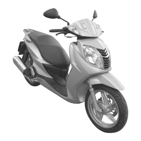
FRAME AND RUNNING GEAR GETTING TO KNOW YOUR SCOOTER PASSWORD 250 i.e. IDENTIFICATION OF MAIN COMPONENTS (left-hand side) 1) Instrument panel 2) Windshield 3) Right-hand mirror 4) Keyswitch 5) Fuses 6) Twin seat 7) Fuel tank cap 8) Pillion grab handles 9) Rear turn indicators 10) Parking and stop lights 11) Number plate light... -
Page 13: Identification Data: Frame N° / Engine N
FRAME AND RUNNING GEAR GETTING TO KNOW YOUR SCOOTER PASSWORD 250 i.e. IDENTIFICATION DATA: FRAME N° / ENGINE N° • To gain access to the vehicle identification number (VIN) (A), lift the right-hand rubber floor mat and remove the cover. •... -
Page 14: Tyres
FRAME AND RUNNING GEAR GETTING TO KNOW YOUR SCOOTER PASSWORD 250 i.e. TYRES Type: Tubeless NOTE It is possible to use tyres with load and speed indexes that are higher than or identical to those indicated. It is however necessary for T.W.I. -
Page 15: Fuel Tank
FRAME AND RUNNING GEAR GETTING TO KNOW YOUR SCOOTER PASSWORD 250 i.e. FUEL TANK To access the fuel tank, proceed as follows: • Place the scooter on the centre stand. • Open the seat by turning the ignition key counter-clock- wise. -
Page 16: Coolant Tank
FRAME AND RUNNING GEAR GETTING TO KNOW YOUR SCOOTER PASSWORD 250 i.e. COOLANT TANK To access the engine coolant tank lift up the rubber mat on the right-hand side. Owing to the position of the tank, the level of coolant with respect to the “MIN”... -
Page 17: Helmet Compartment
FRAME AND RUNNING GEAR GETTING TO KNOW YOUR SCOOTER PASSWORD 250 i.e. HELMET COMPARTMENT • The helmet compartment is under the pillion seat. To gain access to the compartment, put the scooter on its stand and turn the ignition key counter-clockwise to release the seat lock. -
Page 18: Glove Compartment
FRAME AND RUNNING GEAR GETTING TO KNOW YOUR SCOOTER PASSWORD 250 i.e. GLOVE COMPARTMENT The glove compartment is located in the central part of the lower fairing (A) and is suitable for accommodating small personal belongings. It is fitted with a lock that can be opened with the ignition key: turn the key clockwise. -
Page 19: Instrument Panel
FRAME AND RUNNING GEAR GETTING TO KNOW YOUR SCOOTER PASSWORD 250 i.e. INSTRUMENT PANEL Green right-hand turn indicator light Multifunction digital instrument panel To set up the various functions refer to the relative heading in the manual. Fuel level indicator The warning light illuminates to indicate that Analogue instruments. -
Page 20: Digital Instrument Panel
FRAME AND RUNNING GEAR GETTING TO KNOW YOUR SCOOTER PASSWORD 250 i.e. DIGITAL INSTRUMENT PANEL The digital instrument panel provides data for the rider to enable optimum management of the scooter. When the ignition key is set to , all displays on the instrument panel will illuminate for approximately 3 seconds to check that they are working correctly;... -
Page 21: Function Selection And Warning Or Alarm Signals
FRAME AND RUNNING GEAR GETTING TO KNOW YOUR SCOOTER PASSWORD 250 i.e. FUNCTION SELECTION AND WARNING OR ALARM SIGNALS To make the display easier to understand, functions are divided into menus and submenus. Menus Submenus Warning and alarm signals appear automatically whenever the necessity arises. They cannot be selected manually. - Page 22 FRAME AND RUNNING GEAR GETTING TO KNOW YOUR SCOOTER PASSWORD 250 i.e. C) AVE FUNCTION (Average Speed): • This indicates the average speed during a journey. The value is in km/h or mph. The calculation does not take account of stops (speed = 0). To reset, press the MODE button when the scooter is stopped and hold it down until the display shows 0.
-
Page 23: Main Menu
FRAME AND RUNNING GEAR GETTING TO KNOW YOUR SCOOTER PASSWORD 250 i.e. MAIN MENU To access Main Menu function selection mode, hold the down the “MODE” button for 3 sec. when “—” (F) is dis- played in the Submenu. INSTANTANEOUS SPEED FUNCTION: •... -
Page 24: Alarms Function
(see MAINTENANCE TABLE) has been reached. It is the responsibility of local Authorised MALAGUTI Service Centres to reset the warning lights and counters once the relative service operations have been completed. -
Page 25: Miles Or Kilometres Selection
FRAME AND RUNNING GEAR GETTING TO KNOW YOUR SCOOTER PASSWORD 250 i.e. D) DISABLE OIL ALARM Disabling of OIL alarm (CHECK or CHANGE) can only be carried out by authorized personnel, according to the following procedure: • Turn the switch to the OFF position. •... -
Page 26: Right-Hand Control
FRAME AND RUNNING GEAR GETTING TO KNOW YOUR SCOOTER PASSWORD 250 i.e. HANDLEBAR CONTROLS RIGHT-HAND CONTROL 1) Counterweight 2) Throttle grip 3) Front brake lever 4) MODE button: selects the various digital instrument panel functions A) Emergency switch, engine stop. Position - Engine start Position - Engine stop B) Lights switch:... -
Page 27: Keyswitch
FRAME AND RUNNING GEAR GETTING TO KNOW YOUR SCOOTER PASSWORD 250 i.e. KEYSWITCH • The keyswitch controls the ignition circuit, the handle- bar lock and the seat/helmet compartment lock. Ignition disabled (key can be removed) ‘Ready to start’ position (key cannot be re- moved) Handlebar lock on (ignition disabled, key can be removed) -
Page 28: Stands
FRAME AND RUNNING GEAR GETTING TO KNOW YOUR SCOOTER PASSWORD 250 i.e. STANDS CENTRE STAND • The centre stand position is not electronically monitored; you can therefore turn the engine on while the scooter is on the stand. To set the scooter on the stand push on spur (A) and lift the vehicle onto the stand using the rear grab rail. -
Page 29: Owner's Toolkit
FRAME AND RUNNING GEAR GETTING TO KNOW YOUR SCOOTER PASSWORD 250 i.e. OWNER’S TOOLKIT The scooter is equipped with a tool bag stowed under the seat. The bag contains the following tools: A Spark plug wrench B Handle for tool inserts. C Double insert PH2 / Allen wrench size 4 (to be used with handle “B”). -
Page 30: Dimensional Check Of Frame
FRAME AND RUNNING GEAR GETTING TO KNOW YOUR SCOOTER PASSWORD 250 i.e. DIMENSIONAL CHECK OF FRAME If the scooter has been involved in an accident and you suspect even slight distortion of the frame it is essential to perform the dimensional checking procedure before any further “repair or set-up” work. Control dimension (A) must be 1206 mm with a tolerance of ±... -
Page 31: Instructions For Use
INSTRUCTIONS FOR USE FRAME AND RUNNING GEAR INSTRUCTIONS FOR USE PASSWORD 250 i.e. STARTING THE ENGINE The scooter is equipped with an ignition disabling system controlled by the side stand and by the emergency stop switch. The engine cannot be started if the side stand is down or if the emergency stop switch is set to OFF. If the engine is already running it will stop when the side stand is opened or when the emergency stop switch is set to OFF. -
Page 32: Maintenance
The maintenance schedule is based on average riding conditions. Machines subject to severe use or ridden in unusu- ally wet or dusty conditions or off the road require more frequent servicing. NOTE Certain simple checks, i.e. those marked with an asterisk, MAY be performed under the direct respon- sibility of technicians not specifically authorised by MALAGUTI. 11/06... -
Page 33: Transmission Oil
FRAME AND RUNNING GEAR PASSWORD 250 i.e. M A I N T E N A N C E TRANSMISSION OIL LEVEL CHECK 1) Park the scooter on flat ground and set it on its centre stand. 2) Put a container under the engine crankcase. 3) Unscrew oil filler cap (A) and drain plug (B), and allow the oil to flow out. -
Page 34: Engine Oil
FRAME AND RUNNING GEAR M A I N T E N A N C E PASSWORD 250 i.e. ENGINE OIL ENGINE OIL LEVEL CHECK In four-stroke engines the engine oil is used to lubricate timing components, the main bearings, and the thermal unit. -
Page 35: Oil Top-Up
FRAME AND RUNNING GEAR PASSWORD 250 i.e. M A I N T E N A N C E OIL TOP-UP Check the oil level before topping up. Never exceed the “MAX” level when topping up with oil. The difference between the “MIN” and “MAX” marks corresponds to approximately 300 cc. The oil level must never be above the “MAX”... -
Page 36: Front/Rear Brake Fluid
FRAME AND RUNNING GEAR M A I N T E N A N C E PASSWORD 250 i.e. FRONT/REAR BRAKE FLUID Check: every 30 days • Visual inspection is to be performed through sight glass (S) of the brake fluid reservoirs: front brake (A) and rear brake (B), when the scooter is on level ground and per- fectly upright. -
Page 37: Coolant Temperature Indicator
FRAME AND RUNNING GEAR PASSWORD 250 i.e. M A I N T E N A N C E COOLANT TEMPERATURE INDICATOR Coolant temperature is shown on the left-hand side of the display by a specific Bar Graph function. If the temperature is too high, an alarm condition is signalled by a flashing symbol and warning light on the display on the left-hand side of the instrument panel. -
Page 38: Spark Plug
FRAME AND RUNNING GEAR M A I N T E N A N C E PASSWORD 250 i.e. SPARK PLUG Replacement: every 6000 km Recommended type of spark plug: NGK DPR8EA9 The spark plug is an important engine component. • Proper care of the spark plug is essential to maintain the engine in perfect working order. -
Page 39: Adjusting The Rear Shock-Absorbers
FRAME AND RUNNING GEAR PASSWORD 250 i.e. M A I N T E N A N C E ADJUSTING THE REAR SHOCK-ABSORBERS • The rear shock absorbers feature a spring preload ad- justment facility that allows you to adjust suspension performance in relation to the load, type of riding, and road conditions. -
Page 40: Checking The Pads And Discs Of The Front/Rear Brakes (Condition And Wear)
FRAME AND RUNNING GEAR M A I N T E N A N C E PASSWORD 250 i.e. CHECKING THE PADS AND DISCS OF THE FRONT/REAR BRAKES (condition and wear) • It is good practice to check the front/rear pads and discs MIN 2 mm every 2,000 km. -
Page 41: Headlight
FRAME AND RUNNING GEAR PASSWORD 250 i.e. M A I N T E N A N C E HEADLIGHT • To increase night-time visibility the scooter is equipped with quartz (halogen) headlight bulbs. • Low beam/high beam (A) 12V - 35/35 W halogen bulb (HS1) •... - Page 42 FRAME AND RUNNING GEAR M A I N T E N A N C E PASSWORD 250 i.e. REPLACING THE HEADLIGHT BULBS Replacing low beam / high beam headlight bulbs and parking light bulb • Remove upper fairing by undoing the 4 screws (V). Low beam / high beam bulbs (A) •...
-
Page 43: Changing The Front Turn Indicator Bulb
FRAME AND RUNNING GEAR PASSWORD 250 i.e. M A I N T E N A N C E CHANGING THE FRONT TURN INDICATOR BULB • Undo screw (V) (right or left, depending on which bulb you need to replace) responsible for securing the handlebar casings;... -
Page 44: Replacing The Taillight Bulbs
FRAME AND RUNNING GEAR M A I N T E N A N C E PASSWORD 250 i.e. REPLACING THE TAILLIGHT BULBS • Remove the taillight cover (D) by undoing the 2 screws (V). Take care not to scratch the cover. Parking light (A) •... -
Page 45: Number Plate Light
FRAME AND RUNNING GEAR PASSWORD 250 i.e. M A I N T E N A N C E NUMBER PLATE LIGHT • Number plate light (A) 12V - 5W bulb (W5W) To check that number plate light (A) is working, set the light switch (on the right-hand side handlebar control) to its central position and turn the key to starting position. -
Page 46: Fuses
FRAME AND RUNNING GEAR M A I N T E N A N C E PASSWORD 250 i.e. FUSES • The electrical equipment includes eight fuses protect- ing the main components against faults. The fuses are located in the glove compartment. Fuses: A) 15 A Lights... -
Page 47: Battery (12V - 12Ah)
FRAME AND RUNNING GEAR PASSWORD 250 i.e. M A I N T E N A N C E BATTERY (12V - 12AH) The battery housing is in the central channel. INSTALLING THE BATTERY • Take a fully charged battery; • apply the adhesive strip supplied with the scooter as shown in figure, removing the two protective films from the ends of the adhesive area, as shown by the arrow in the drawing (A);... -
Page 48: Removing The Battery
FRAME AND RUNNING GEAR M A I N T E N A N C E PASSWORD 250 i.e. • fit the battery and ensure it is correctly seated; • connect the battery cables; • connect: the positive pole (+) to the RED cables ; the negative pole (-) to the BLACK cables; •... -
Page 49: Instrument Panel Windshield
FRAME AND RUNNING GEAR D I S A S S E M B LY PASSWORD 250 i.e. INSTRUMENT PANEL WINDSHIELD • Remove the two covers (A) taking care not to snap off the tabs holding them in place. • Undo screws (V4) and remove the windshield. •... -
Page 50: Instrument Panel
FRAME AND RUNNING GEAR D I S A S S E M B LY PASSWORD 250 i.e. • Remove the handlebar cover (A) upwards complete with the instrument panel. Take care not to damage instrument panel connector cable (B). INSTRUMENT PANEL •... -
Page 51: Accessibility
FRAME AND RUNNING GEAR D I S A S S E M B LY PASSWORD 250 i.e. ACCESSIBILITY Removing the front handlebar cover and instrument panel provides access to the following components: • Instrument panel connector (A). • Connector for LH handlebar control (B). •... -
Page 52: Ambient Temperature Sensor
FRAME AND RUNNING GEAR D I S A S S E M B LY PASSWORD 250 i.e. AMBIENT TEMPERATURE SENSOR • (Remove windshield). • (Remove upper handlebar cover). • Detach connector (A). • Remove sensor (B) from lower handlebar cover (C). The sensor must be mounted EXTERNAL- LY to the lower handlebar cover as shown in the figure. -
Page 53: Front Fairing
FRAME AND RUNNING GEAR D I S A S S E M B LY PASSWORD 250 i.e. • (Remove upper handlebar cover). • Undo screw (V) and remove counterweight. • Undo screws (V2) and remove LH control. Use compressed air to reduce friction when removing and refitting the twist grip. -
Page 54: Accessibility
FRAME AND RUNNING GEAR D I S A S S E M B LY PASSWORD 250 i.e. • Grip front fairing (A) and lift the lower part slightly and disconnect connector (B); now remove the fairing. When refitting take care not to pinch the headlight cable. -
Page 55: Headlights
FRAME AND RUNNING GEAR D I S A S S E M B LY PASSWORD 250 i.e. HEADLIGHTS • (Remove front fairing). • Undo screws (V6) and remove headlights. To change the bulbs refer to “Replacing headlight bulbs” (page 42) GRILLE •... -
Page 56: Front Mudguard
FRAME AND RUNNING GEAR D I S A S S E M B LY PASSWORD 250 i.e. FRONT MUDGUARD • Undo screw (V) and remove nut (D) responsible for securing hydraulic hose clamp (A). • Unscrew screws (V4) on the underside of the mudguard. •... -
Page 57: Speedometer Sensor
FRAME AND RUNNING GEAR D I S A S S E M B LY PASSWORD 250 i.e. SPEEDOMETER SENSOR • Undo screw (V) ensuring the spacer does not fall. • Disconnect the electronic transmission connector (See “Systems” section). When refitting, use a feeler gauge to check that the sensor - disc gap is 1¸2 mm. -
Page 58: Checking Front Brake Wear
FRAME AND RUNNING GEAR D I S A S S E M B LY PASSWORD 250 i.e. CHECKING FRONT BRAKE WEAR • Use this opportunity to check the disc for wear. Should it be scored or unevenly worn, it can be reground. If disc thickness has worn to less than 4.5 mm the discs must be changed. -
Page 59: Front Wheel
FRAME AND RUNNING GEAR D I S A S S E M B LY PASSWORD 250 i.e. FRONT WHEEL Before disassembly, support the frame at the centre to prevent the scooter from fall- ing. • (Remove speedometer sensor). • (Remove front brake caliper). •... -
Page 60: Front Brake Disc
FRAME AND RUNNING GEAR D I S A S S E M B LY PASSWORD 250 i.e. FRONT BRAKE DISC • (Remove speedometer sensor). • (Remove front brake caliper). • (Remove front wheel). • Undo screws (V5). When reassembling, use new screws and apply a high strength threadlocker. -
Page 61: Left And Right Half Shield
FRAME AND RUNNING GEAR D I S A S S E M B LY PASSWORD 250 i.e. LEFT AND RIGHT HALF SHIELD • (Remove front fairing). • Remove rubber mats (A). • Undo screws (V4). 11/06... - Page 62 FRAME AND RUNNING GEAR D I S A S S E M B LY PASSWORD 250 i.e. • Undo screws (V4). • Undo screw (V1). Pay attention: screw (V1) is internal and con- cealed by the fairing. Remove the half shield. 11/06...
-
Page 63: Accessibility
FRAME AND RUNNING GEAR D I S A S S E M B LY PASSWORD 250 i.e. ACCESSIBILITY Removing the right-hand half shield provides access to the following components: • Fuse connections (A). • Horn (B). • Saddle opening transmission cable gland (C). •... -
Page 64: Horn
FRAME AND RUNNING GEAR D I S A S S E M B LY PASSWORD 250 i.e. Removing the left-half shield provides access to the fol- lowing components: • Coolant hoses (F). HORN • (Remove right-hand half shield). • Undo screw (V) and disconnect the cables. For subsequent reassembly, connect BLUE wire (A) to the horn INTERNAL terminal and ORANGE wire (B) to the EXTERNAL termi-... -
Page 65: Right And Left Lateral Sub Panels
FRAME AND RUNNING GEAR D I S A S S E M B LY PASSWORD 250 i.e. RIGHT AND LEFT LATERAL SUB PANELS • (Remove rubber mats). • Undo screws (V2). • Grasp lateral sub panel (A) and disengage it from foot- board attachment point (B) by turning it outwards. -
Page 66: Accessibility
FRAME AND RUNNING GEAR D I S A S S E M B LY PASSWORD 250 i.e. ACCESSIBILITY Removing the right-hand sub panel provides access to the following components: • Seat lock transmission (A). NOTE If you need to open the helmet compartment WITHOUT the key, remove rubber protection (B) and then pull the two control cable sheaths. -
Page 67: Voltage Regulator
FRAME AND RUNNING GEAR D I S A S S E M B LY PASSWORD 250 i.e. Removing both sub panels provides access to the following components: • Voltage regulator (D) • “CDI” control unit (E) VOLTAGE REGULATOR • Disconnect connector (A) by pressing the suitable tab. •... -
Page 68: Battery Compartment Tunnel Cover
FRAME AND RUNNING GEAR D I S A S S E M B LY PASSWORD 250 i.e. BATTERY COMPARTMENT TUNNEL COVER • Undo screws (V4). • Gently pull tunnel cover (A) towards the front of the scooter to remove it. 11/06... -
Page 69: Right Side Accessibility
FRAME AND RUNNING GEAR D I S A S S E M B LY PASSWORD 250 i.e. RIGHT SIDE ACCESSIBILITY Removing the tunnel cover provides access to the following components: A - Starter motor relay B - Flasher unit C - Injection diagnosis plug connector D - Starter motor disconnection relay (C) (WHITE) E - Fan relay (YELLOW) F - Injection loads relé... -
Page 70: Battery
FRAME AND RUNNING GEAR D I S A S S E M B LY PASSWORD 250 i.e. BATTERY See “Installing the battery”. Note that: - the battery leads are routed through opening (A) in the rear of the cover; - cover (B) can be removed ONLY if all battery leads are disconnected;... -
Page 71: Sub-Fairing
FRAME AND RUNNING GEAR D I S A S S E M B LY PASSWORD 250 i.e. SUB-FAIRING • (Disassemble the front leg shield). • (Remove half shields). • (Remove front mudguard). • Undo screws (V2a). • Undo screws (V2b). •... -
Page 72: Lower Fairing
FRAME AND RUNNING GEAR D I S A S S E M B LY PASSWORD 250 i.e. LOWER FAIRING • (Remove upper fairing). • (Remove front half fairings). • (Remove sub-fairing). • Remove keyswitch cover (A), rotating it counter-clock- wise through ¼ of a turn. •... - Page 73 FRAME AND RUNNING GEAR D I S A S S E M B LY PASSWORD 250 i.e. • Undo bag hook screws (V2). • Undo screw (V). • Undo screw (V). 11/06...
- Page 74 FRAME AND RUNNING GEAR D I S A S S E M B LY PASSWORD 250 i.e. • Undo screws (V2). • Disengage the tab that secures the lower fairing to the footboard, pull lower edge (B) of the lower fairing to- wards the front of the scooter;...
-
Page 75: Footboard
FRAME AND RUNNING GEAR D I S A S S E M B LY PASSWORD 250 i.e. FOOTBOARD • (Remove the battery compartment tunnel cover). • (Remove the battery). • (Remove the sub-panels). • (Remove right/left half fairings). • (Remove lower fairing). •... -
Page 76: Coolant Expansion Tank
FRAME AND RUNNING GEAR D I S A S S E M B LY PASSWORD 250 i.e. COOLANT EXPANSION TANK • (Remove footboard). DANGER OF BURNS! Before proceeding, make sure that the cool- ant temperature is lower than 50°C. • Undo the radiator cap. •... -
Page 77: Side Stand
FRAME AND RUNNING GEAR D I S A S S E M B LY PASSWORD 250 i.e. SIDE STAND • Detach springs (A) and undo screw (V). 20 ± 15% SIDE STAND SWITCH • Undo screws (V2). 5 ± 20% •... -
Page 78: Centre Stand
FRAME AND RUNNING GEAR D I S A S S E M B LY PASSWORD 250 i.e. CENTRE STAND Prop up the centre of the scooter to prevent it from falling. • Detach two springs (A). • Remove snap ring (B), washer (C) then remove pin (D). When reassembling, ALWAYS insert washer (C) UNDER the snap ring. -
Page 79: Main Electrical System
FRAME AND RUNNING GEAR D I S A S S E M B LY PASSWORD 250 i.e. MAIN ELECTRICAL SYSTEM 11/06... -
Page 80: Radiator
FRAME AND RUNNING GEAR D I S A S S E M B LY PASSWORD 250 i.e. RADIATOR • (Remove upper fairing). • (Remove upper half fairings). • (Remove sub-fairing). • (Remove lower fairing). DANGER OF BURNS! Before proceeding, make sure that the cool- ant temperature is lower than 50 °C. - Page 81 FRAME AND RUNNING GEAR D I S A S S E M B LY PASSWORD 250 i.e. • Undo screws (V4). • Undo screws (V2). • Remove clamps (C). NOTE For the subsequent assembly phase the clamps must be positioned immediately be- hind the point at which the metal pipe diame- ter increases.
- Page 82 FRAME AND RUNNING GEAR D I S A S S E M B LY PASSWORD 250 i.e. NOTE Use pliers (Beta 1472 FS) to remove the clamps. • Detach rubber hoses (D) from metal pipes. NOTE To facilitate this operation prise the hose by inserting a screwdriver under it while simul- taneously pulling it.
-
Page 83: Fan Unit
FRAME AND RUNNING GEAR D I S A S S E M B LY PASSWORD 250 i.e. FAN UNIT • Undo screws (V3). NOTE For reassembly position the fan as shown in the figure and position clamp (A) under the screw as indicated. -
Page 84: Keyswitch
FRAME AND RUNNING GEAR D I S A S S E M B LY PASSWORD 250 i.e. • Replenish the radiator coolant and then close filler cap (A). • Start the engine and run it at IDLE speed for a few minutes then switch off and unscrew the bleed screw again to vent any residual air. -
Page 85: Seat
FRAME AND RUNNING GEAR D I S A S S E M B LY PASSWORD 250 i.e. SEAT • Release the seat lock with the key and tip it to its open position. • Unscrew nuts (D2) and remove the seat, resting it on a supporting surface with the upholstery upwards. - Page 86 FRAME AND RUNNING GEAR D I S A S S E M B LY PASSWORD 250 i.e. SEAT LOCK • (Remove seat). • (Remove helmet compartment). • Raise rear of helmet compartment (A) slightly. • Remove nut covers (B) and disengage transmission cable (C) from metal clamp (D).
-
Page 87: Accessibility
FRAME AND RUNNING GEAR D I S A S S E M B LY PASSWORD 250 i.e. ACCESSIBILITY Remove the helmet storage container to gain access to the components below: A) Fuel tank B) Fuel probe C) Fuel pump D) Suction air temperature sensor connector E) Engine stepper F) “TPS”... -
Page 88: Throttle Body And Aspiration Connector
FRAME AND RUNNING GEAR D I S A S S E M B LY PASSWORD 250 i.e. THROTTLE BODY AND ASPIRATION CONNECTOR NOTE For access to the throttle body, remove the saddle and the helmet storage space. Suction air pressure sensor tube Suction air pressure sensor connector Suction air pressure sensor Suction air pressure sensor shaft... -
Page 89: Fuel Level Sensor
FRAME AND RUNNING GEAR D I S A S S E M B LY PASSWORD 250 i.e. FUEL LEVEL SENSOR • (Remove seat). • (Remove seat lock). • (Remove helmet compartment). • Open clamp (A) and free the electrical cable; discon- nect connector (B) and undo screws (V4). -
Page 90: Pillion Grab Handle
FRAME AND RUNNING GEAR D I S A S S E M B LY PASSWORD 250 i.e. PILLION GRAB HANDLE • (Remove seat). • (Remove helmet compartment). • (Remove seat lock). • Undo screws (V2) and (V) and remove handle (A). 43 ±... -
Page 91: Taillight
FRAME AND RUNNING GEAR D I S A S S E M B LY PASSWORD 250 i.e. TAILLIGHT See “Replacing the taillight bulb” (page 44) To remove the complete unit first free the electrical cables from cable tie (A); now de- tach connector (B) located under the pillion grab handle (see “Pillion grab handle”). - Page 92 FRAME AND RUNNING GEAR D I S A S S E M B LY PASSWORD 250 i.e. TAILLIGHT • Insert the electrical cable through opening (A). • Fit the taillight unit, paying attention to attachment point (B) in the scooter number plate holder rear fairing; the attachment point must interlock with tab on the tail- light.
-
Page 93: Number Plate Light
FRAME AND RUNNING GEAR D I S A S S E M B LY PASSWORD 250 i.e. NUMBER PLATE LIGHT See “Replacing the number plate light bulb” (page 45). • (Remove taillight). • Open clamp (A) and free the electrical cable. At the time of reassembly the electrical ca- ble must be restrained in the clamp again. -
Page 94: Rear Fairing
FRAME AND RUNNING GEAR D I S A S S E M B LY PASSWORD 250 i.e. REAR FAIRING • (Remove seat). • (Remove helmet compartment). • (Remove seat lock). • (Remove taillight). • (Remove pillion grab handle). • (Remove battery compartment tunnel). •... -
Page 95: Accessibility
FRAME AND RUNNING GEAR D I S A S S E M B LY PASSWORD 250 i.e. ACCESSIBILITY Removing the rear fairing provides access to the follow- ing components: Left side • Drip container pipe (A). Right side • Flywheel connectors (B). •... -
Page 96: Fuel Tank
FRAME AND RUNNING GEAR D I S A S S E M B LY PASSWORD 250 i.e. FUEL TANK • (Remove battery compartment tunnel). • (Remove seat). • (Remove helmet compartment). • (Remove pillion grab handle). • (Remove rear fairing). •... - Page 97 FRAME AND RUNNING GEAR D I S A S S E M B LY PASSWORD 250 i.e. • Undo screws (V4). There is a bushing (C) under each screw (V4). The tank support must rest on a rubber SilentBlock (D); ensure the rubber mount does not fall.
-
Page 98: Silencer
FRAME AND RUNNING GEAR D I S A S S E M B LY PASSWORD 250 i.e. SILENCER Before working on the silencer and the ex- haust manifold wait until all the components have cooled down and always wear suitable protective gloves. -
Page 99: Lambda Probe And Discharge Collector
FRAME AND RUNNING GEAR D I S A S S E M B LY PASSWORD 250 i.e. LAMBDA PROBE AND DISCHARGE COLLECTOR • Open clamps (A - B). • Disconnect the connector (C). • Unscrew the Lambda probe (D). 45 ± 10% DISCHARGE COLLECTORS •... -
Page 100: Rear Shock Absorbers
FRAME AND RUNNING GEAR D I S A S S E M B LY PASSWORD 250 i.e. REAR SHOCK ABSORBERS Before removing the rear shock absorbers support the centre of the frame to prevent the scooter from falling. • First undo lower screw (Va); then upper screw (Vb). 24 ±... -
Page 101: Rear Mudguard
FRAME AND RUNNING GEAR D I S A S S E M B LY PASSWORD 250 i.e. REAR MUDGUARD • Undo screws (V2). 3,5 ± 20% • Undo screw (V). • Undo screw (V) then remove mudguard towards rear of scooter. -
Page 102: Rear Brake Caliper
FRAME AND RUNNING GEAR D I S A S S E M B LY PASSWORD 250 i.e. REAR BRAKE CALIPER • Undo screws (V2). • Undo brake fluid line screw (V) and detach brake line from caliper. When reassembling, renew the gaskets of the brake fluid line screw. -
Page 103: Rear Wheel
FRAME AND RUNNING GEAR D I S A S S E M B LY PASSWORD 250 i.e. REAR WHEEL • (Remove silencer). • (Remove right-hand rear shock-absorber). • (Remove mudguard). • (Remove rear brake caliper). • Undo nut (D) with washer and screws (V2). 135 ±... -
Page 104: Assembly Of Rear Wheel
FRAME AND RUNNING GEAR D I S A S S E M B LY PASSWORD 250 i.e. NOTE To replace bearing (D) located inside the swin- garm use a puller tool after having removed snap ring (E). • Remove rear wheel (F). Spacer (H) is located on shaft (G) behind the wheel. -
Page 105: Rear Disc
FRAME AND RUNNING GEAR D I S A S S E M B LY PASSWORD 250 i.e. REAR DISC • (Remove silencer). • (Remove rear brake caliper). • (Remove right-hand shock absorber). • (Remove rear mudguard). • (Remove rear wheel). The thickness of the rear brake disc must NEVER be less than 3.5 mm;... -
Page 106: Filter Box
FRAME AND RUNNING GEAR D I S A S S E M B LY PASSWORD 250 i.e. FILTER BOX • (Remove seat). • (Remove helmet compartment). • Disconnect sensor connector (A) for suction air temperature. • Open the clamp and disconnect oil vapour recovery hose (B). - Page 107 FRAME AND RUNNING GEAR D I S A S S E M B LY PASSWORD 250 i.e. • Undo screw (V). • Undo the Allen screw (V), accessible from opening (F). 11/06...
- Page 108 FRAME AND RUNNING GEAR D I S A S S E M B LY PASSWORD 250 i.e. • Remove filter box (E) from the scooter, prising gently in throttle body connection point (F). • Undo screws (V7) to open the filter box. To unscrew the screws (V7) you must use a fool-proofing “TORX”...
-
Page 109: Pillion Footrest
FRAME AND RUNNING GEAR D I S A S S E M B LY PASSWORD 250 i.e. PILLION FOOTREST • Undo screws (V2) and remove plastic cover (A). • Remove ring (B) and withdraw pivot pin (C). • Remove footrest (D). •... -
Page 110: Engine
FRAME AND RUNNING GEAR D I S A S S E M B LY PASSWORD 250 i.e. ENGINE • (Remove silencer, including collector and lambda probe). • (Remove filter box). Before proceeding with the engine disassembly operation, prop up the centre of the frame to prevent the scooter from falling. - Page 111 FRAME AND RUNNING GEAR D I S A S S E M B LY PASSWORD 250 i.e. • Unscrew clamp (F). • Detach hose (G) from water pump (P). Before disconnecting hose (G), empty the cooling system (see “Removing the radia- tor”).
- Page 112 FRAME AND RUNNING GEAR D I S A S S E M B LY PASSWORD 250 i.e. • Insert a jack under the engine and raise it until it is in contact with the engine; now unscrew nut (M) and re- move engine mounting bolt (N).
-
Page 113: Brake Master Cylinders
FRAME AND RUNNING GEAR D I S A S S E M B LY PASSWORD 250 i.e. BRAKE MASTER CYLINDERS Empty the brake fluid circuit, draining the fluid into a suit- able container for disposal in compliance with statutory environmental legislation. Beware of possible spills and splashes of brake fluid. -
Page 114: Handlebar
FRAME AND RUNNING GEAR D I S A S S E M B LY PASSWORD 250 i.e. HANDLEBARS • (Remove windshield). • (Remove upper handlebar cover). • (Remove front/rear brake master cylinders). • (Disconnect right and left connectors). • Cut all cable and hose ties. •... -
Page 115: Front Fork
FRAME AND RUNNING GEAR D I S A S S E M B LY PASSWORD 250 i.e. FRONT FORKS • (Remove windshield). • (Remove upper handlebar cover). • (Remove handlebars). • (Remove mudguard). • (Remove front brake calliper). • (Remove front wheel). •... -
Page 116: Front Damper
FRAME AND RUNNING GEAR D I S A S S E M B LY PASSWORD 250 i.e. FRONT STANCHION RIGHT • (Remove mudguard). • (Remove wheel). LEFT • (Remove mudguard). • (Remove wheel). • (Remove brake calliper). • (Remove odometer pick-up). Before proceeding with the disassembly operation, prop up the centre of the frame to prevent the scooter falling. -
Page 117: Checking The Oil Level In The Damper
FRAME AND RUNNING GEAR D I S A S S E M B LY PASSWORD 250 i.e. CHECKING THE OIL LEVEL IN THE STANCHION If the front suspension bottoms out or makes anomalous noises, check the oil level in the stanchions as follows: •... -
Page 118: Changing The Fork Oil
FRAME AND RUNNING GEAR D I S A S S E M B LY PASSWORD 250 i.e. CHANGING THE FORKS OIL • Place a container under the stanchion and remove screw (V). • Allow as much oil as possible to drain out. •... -
Page 119: Brake Calipers
FRAME AND RUNNING GEAR D I S A S S E M B LY PASSWORD 250 i.e. BRAKE CALLIPERS Anomalous resistance or a spongy feel when operating the brake lever denote impaired operation of the brake system. NOTE The minimum thickness of the pads (front and rear brakes) is 2 mm. REMOVING THE FRONT CALLIPER NOTE After having removed the calliper from its seat, place a recipient under it to collect the brake fluid. -
Page 120: Overhaul
FRAME AND RUNNING GEAR D I S A S S E M B LY PASSWORD 250 i.e. OVERHAUL • Undo screws (V2). 20 ± 20% • Apply a low pressure jet of compressed air to the oil- way in which the brake fluid union was fitted in order to cause the two plungers to be ejected from the brake calliper body. - Page 121 FRAME AND RUNNING GEAR D I S A S S E M B LY PASSWORD 250 i.e. REMOVING THE REAR CALLIPER • Undo screws (V2). • Remove calliper assy. (A) complete with the brake hose. 30 ± 20% REPLACING THE REAR CALLIPER •...
- Page 122 FRAME AND RUNNING GEAR D I S A S S E M B LY PASSWORD 250 i.e. • Apply a low pressure jet of compressed air to the oil- way (E) in which the brake fluid union was fitted in or- der to cause the two plungers to be ejected from their seats in the two halves of the calliper;...
-
Page 123: Brake System
FRAME AND RUNNING GEAR D I S A S S E M B LY PASSWORD 250 i.e. BRAKE SYSTEM FRONT BRAKE MASTER CYLINDER REAR BRAKE MASTER CYLINDER REAR CALIPER FRONT CALIPER 11/06... -
Page 124: Bleeding The Brake System
FRAME AND RUNNING GEAR D I S A S S E M B LY PASSWORD 250 i.e. BLEEDING THE BRAKE SYSTEM FRONT CALLIPER NOTE Position the scooter so that it is stable and perfectly level. • Remove master cylinder reservoir cover (A) (right-hand side), unscrewing the relative two screws, so that you can replenish the brake fluid.
Need help?
Do you have a question about the Password 250 i.e. and is the answer not in the manual?
Questions and answers