
Subscribe to Our Youtube Channel
Related Manuals for Valcom V-WMCA


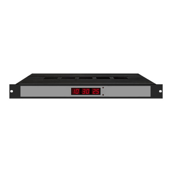
Summary of Contents for Valcom V-WMCA
- Page 1 Valcom Master Clock (V2) V-WMCA V-GPSA V-GPS-TX Valcom, Inc. 5614 Hollins Road Roanoke, VA 24019...
-
Page 2: Table Of Contents
2 Wire Communication................Page 6 Sync Wire Communication…………………………………………………... Input Connections Pages 7 - 9 Sync-Wire Inputs..................Page 10 Patch Cable Installation................Programming the Valcom Master Clock Page 11 Setting the Time..................Pages 11-12 Setting the Date..................Page 12 Technical Mode..................Page 12 Setting the RS485 Data Rate.............. -
Page 3: Wall Mount Installation
Valcom Master Clock (V2) Wall Mount Installation Fig 1 Instructions 1. Remove the cover of the wiring panel (Fig 1). 2. Mark the four drilling points on the wall based on the drawing above. 3. Drill the holes for the anchors supplied in the mounting kit at the designated markings from step 1. -
Page 4: Before You Get Started
RS485 Input/Output - This terminal block is where connections would be landed for RS485 communi- cation to and from other Valcom systems. Inputs - This terminal block is where connections would be landed to use the Valcom Master Clock as a slave clock when being controlled by another system. -
Page 5: Wire Communication
Valcom Master Clock (V2) System Connections - Wired Systems 2 Wire Communication 19 18 DATA IN V-C6124P and the V-CCU V-C6124P V-CCU are ordered as a V-VCU 24 volt outputs 24 VDC IN 2 Wire Digital Output to Clocks - + -... -
Page 6: Sync Wire Communication
Valcom Master Clock (V2) System Connections - Wired Systems Sync-Wire Communication via Clock #1 or #2 10 Amp Contact Rating Page 6... -
Page 7: Input Connections Sync-Wire Inputs
Valcom Master Clock (V2) Inputs - Sync-Wire Inputs Installation This system can accommodate both a primary and secondary (for backup) auxiliary time synchronization input. The following protocols cannot be used simultaneously: 59 minute sync, 58 minute 1-4 sync, National Time/ Rauland, Dukane Digital, Rauland Digital and once a day Pulse. - Page 8 Valcom Master Clock (V2) Inputs - Sync-Wire Inputs Installation National Time/Rauland Dry Contact Closure 110VAC Interface 24VAC Interface N.O. Rauland Digital Input Output Page 8...
- Page 9 Valcom Master Clock (V2) Inputs - Sync-Wire Inputs Installation Dukane Digital Reset Minute Pulse Ground Once a Day Pulse Dry Contact Closure N.O. Page 9...
-
Page 10: Patch Cable Installation
Wall Jack to Network 1) Connect a patch cable to the RJ45 port on the Valcom Master Clock as shown in Fig 1.1. 2) Connect the other end of the patch cable to an Ethernet jack connected to the network. -
Page 11: Programming The Valcom Master Clock
Valcom Master Clock (V2) Programming the Valcom Master Clock Programming may be accomplished manually or through the web interface. See page 19. Setting the Time from the LED Display To set the time, press the top button to change the hour and/or the bottom button the set the minute. -
Page 12: Technical Mode
Valcom Master Clock (V2) Press the top button to enter option 3. The number “3” will appear on the left side of the LED display. This prompt allows the user to set the day. Use the bottom button to scroll between “01-31”. -
Page 13: Setting 12 Or 24 Hour Mode
Valcom Master Clock (V2) Press the top button to enter option 13. The num- ber “13” will appear on the left side of the LED display. This option allows the user to set 12 or 24 hour mode. Press the bottom button to scroll be- tween “12”... -
Page 14: Setting Clock #2 Relay Output
Valcom Master Clock (V2) Press the top button to enter option 23. The num- ber “23” will appear on the left side of the LED display. This option allows the user to set the sec- onds at which the relay will close. Press the bottom button to scroll through “00-59”. -
Page 15: Setting The Primary Input
Valcom Master Clock (V2) Press the top button to enter option 27. The num- ber “27” will appear on the left side of the LED display. This option allows the user to set the min- utes at which the relay will close. Press the bottom button to scroll through “00-59”. -
Page 16: Setting The Secondary Input
Valcom Master Clock (V2) Press the top button to enter option 31. The number “31” will appear on the left side of the LED display. This option allows the user to select the secondary auxiliary input. Press the bottom button to scroll between “1-13”... - Page 17 Valcom Master Clock (V2) Press the top button to enter option 35. The num- ber “35” will appear on the left side of the LED display. This option allows the user to set the min- utes that the time is to go to when Once A Day Pulse is selected.
-
Page 18: Sending Diagnostics
Valcom Master Clock (V2) Press the top button to enter option 50. The num- ber “50” will appear on the left side of the LED display. This option allows the user to enter diag- nostic mode. Press the bottom button to scroll be- tween “E - d”. -
Page 19: Sync-Wire Protocol Definitions
Valcom Master Clock (V2) System Connections - Wired Systems Sync-Wire Communication - Protocol Definitions “1” = 58 minute (1) - The hourly correction for 55 seconds every hour from XX:58:05 to XX:59:00. The daily correction (5 a.m. & 5 p.m.) is ten correction cycles sent to the relay (each for 95 seconds) beginning at 5:05:00, 5:07:00, 5:09:00, 5:11:00, 5:13:00, 5:15:00, 5:17:00, 5:19:00, 5:21:00, and 5:23:00. -
Page 20: Web Browser Programming
Valcom Master Clock (V2) Web Browser Programming Log-In Password - There are two levels of passwords that will enable the user to access features. The first level is the user level programming that includes features like setting the time, date, adding and editing events and schedule changes. -
Page 21: Main Menu
Valcom Master Clock (V2) Web Browser Programming Main Menu Technician Menu - This link will access the Technician Menu log-in page. The Technician Menu is password pro- tected and has access to system settings, IP settings, as well as feature settings for the master clock. -
Page 22: Technician Level Menu
Valcom Master Clock (V2) Web Browser Programming Technician Level Menu System Settings - This link, when clicked, will enter the System Settings pages. These pages include the user pass- word, the RS485 data rate, setting the offset, the input selection, setting Clock #1 and Clock #2 sync-wire protocol outputs and resetting the unit back to manufacturer’s default settings. -
Page 23: System Settings
Valcom Master Clock (V2) Web Browser Programming System Settings Page 1 Page 23... - Page 24 Valcom Master Clock (V2) Web Browser Programming System Settings Page 1 (cont.) User Password - This field allows the user to enter a new password for the user level programming. The default is 1111. RS485 Data Rate - These fields allow the user to set how often RS485 will be transmitted from the master clock.
- Page 25 Valcom Master Clock (V2) Web Browser Programming System Settings Page 2 Page 25...
- Page 26 Valcom Master Clock (V2) Web Browser Programming System Settings Page 2 Input Selection - This drop-down list allows the user to select which input will control the master clock. The choices are: Real Time Clock • 58 Minute Sync_3 ...
-
Page 27: Ip Settings
Valcom Master Clock (V2) Web Browser Programming IP Settings Page 1 Page 27... - Page 28 Valcom Master Clock (V2) Web Browser Programming IP Settings Page 1 (cont.) Gateway IP Address - This field allows the user to set the Gateway IP address for the master clock. Subnet Mask - This field allows the user set the Subnet Mask for the master clock.
- Page 29 Valcom Master Clock (V2) Web Browser Programming IP Settings Page 2 Retry Failed Server After - This field allows the user to specify how many times it will attempt to access the time from a server before it moves on to the next one.
- Page 30 Valcom Master Clock (V2) Web Browser Programming IP Settings Page 3 (GPS, SNTP Client) MAC Address (Read Only) - This displays the MAC address for the master clock. IP Address - This display the IP address for the master clock.
-
Page 31: Clock Features
Valcom Master Clock (V2) Web Browser Programming Clock Features Display Format - This drop-down list allows the user to select whether they want 12 hour or 24 hour mode to be dis- played on the LED display. Daylight Savings Time - This drop-down list allows the user to select which daylight savings time option they want. -
Page 32: Database Maintenance
Valcom Master Clock (V2) Web Browser Programming Database Maintenance Upload Database - This button, when pressed, will upload the current schedules and events, and place it in a file for backup purposes. Choose File - This button, when pressed, will allow the user to browse for the saved .db file that contains the saved events and schedules. -
Page 33: Frequently Asked Questions
Yes, the Valcom Master Clock can be accessed through a cross-over cable or via a LAN connection. What is the maximum length I can go with the GPS cable? When the GPS option is purchased, a 75 foot cable comes standard with the unit. This is Valcom’s recom- mended longest distance. -
Page 34: Troubleshooting
The master clock will not power up. What do I do? Make sure the power cord is securely connected to the power outlet and to the back of the Valcom Master Clock. Upon being connected to power, the master clock should boot up instantly. There is not an on/off switch.
Need help?
Do you have a question about the V-WMCA and is the answer not in the manual?
Questions and answers