
Subscribe to Our Youtube Channel
Related Manuals for Valcom V-WMCA Series


Summary of Contents for Valcom V-WMCA Series
- Page 1 Installation Manual V14.8 V-WMCA/V-GPSA/ V-GPS-TX Series Master Clock Valcom, Inc. P. 540-563-2000 5614 Hollins Road F. 540-362-9800 Roanoke, VA 24019 www.valcom.com Current as of November 2016...
- Page 2 Valcom, Inc. P. 540-563-2000 5614 Hollins Road F. 540-362-9800 Roanoke, VA 24019 www.valcom.com V-WMCA/V-GPSA/V-GPS-TX Master Clock Table of Contents Table of Contents - Email Alerts 50-51 Important Safety Instructions - System Settings 52-53 System Preparations - Synchronization Installing a Master Clock...
- Page 3 Valcom, Inc. P. 540-563-2000 5614 Hollins Road F. 540-362-9800 Roanoke, VA 24019 www.valcom.com Important Safety Instructions VERY IMPORTANT: KNOW YOUR COMMUNICATION PROTOCOL This master clock is designed to support multiple communication protocols. To run any clock system properly, the master clock requires the correct wiring format. It is very important that you only follow the wiring instructions appropriate to your system’s communication protocol.
- Page 4 Valcom, Inc. Valcom, Inc. P. 540-563-2000 P. 540-563-2000 5614 Hollins Road 5614 Hollins Road F. 540-362-9800 F. 540-362-9800 Roanoke, VA 24019 Roanoke, VA 24019 www.valcom.com www.valcom.com System Preparations Identify an appropriate location to install the master clock. The location should be accessible to the installer, and should be easily able to access its time base. This...
- Page 5 Valcom, Inc. P. 540-563-2000 5614 Hollins Road F. 540-362-9800 Roanoke, VA 24019 www.valcom.com Installing a Master Clock - Wall Mount Included in Package Description Quantity Picture Master Clock Power Cable (E-PWR-CBL-KIT-1) Paper Mounting Template (M-23-MTEMP-1) Included in Mounting Kit (M-SURF-MNT-KIT1) #10-1.5 Sheet Metal Screw...
- Page 6 Valcom, Inc. P. 540-563-2000 5614 Hollins Road F. 540-362-9800 Roanoke, VA 24019 www.valcom.com Installing a Master Clock - Wall Mount 1) Use a ruler, a level, and the provided template to 2) Use a drill to drill holes into the wall at the mark four points on the wall.
- Page 7 Valcom, Inc. P. 540-563-2000 5614 Hollins Road F. 540-362-9800 Roanoke, VA 24019 www.valcom.com Installing a Master Clock - Wall Mount 5) Unscrew the bottom panel from the clock. 6) Remove the metal punch-outs so that cables can be installed. Thread the cables through the punch-out holes.
- Page 8 Valcom, Inc. Valcom, Inc. P. 540-563-2000 P. 540-563-2000 5614 Hollins Road 5614 Hollins Road F. 540-362-9800 F. 540-362-9800 Roanoke, VA 24019 Roanoke, VA 24019 www.valcom.com www.valcom.com 9 10 Installing a Master Clock - Wall Mount 9) Hang the master clock on the wall screws. Do...
- Page 9 Valcom, Inc. P. 540-563-2000 5614 Hollins Road F. 540-362-9800 Roanoke, VA 24019 www.valcom.com Installing a Master Clock - Rack Mount Included in Package Included in Package Description Quantity Picture Master Clock Power Cable (E-PWR-CBL-KIT-1) Please Note: A user will also have to provide a Phillips-head screwdriver, a server/network cabinet, and the screws and bolts needed to attach the master...
- Page 10 Valcom, Inc. P. 540-563-2000 5614 Hollins Road F. 540-362-9800 Roanoke, VA 24019 www.valcom.com Installing a Master Clock - Rack Mount 1) Thread any necessary cables through the back of 2) Unscrew the back panel from the master clock. the network cabinet, including the cables for power, inputs, outputs, and the remote antenna if it applies.
- Page 11 Valcom, Inc. P. 540-563-2000 5614 Hollins Road F. 540-362-9800 Roanoke, VA 24019 www.valcom.com Installing a Master Clock - Rack Mount 5) Attach the power cables to the appropriate port 6) Use a screwdriver to reattach the master clock on the master clock.
-
Page 12: Paper Mounting Template
Valcom, Inc. Valcom, Inc. P. 540-563-2000 P. 540-563-2000 5614 Hollins Road 5614 Hollins Road F. 540-362-9800 F. 540-362-9800 Roanoke, VA 24019 Roanoke, VA 24019 www.valcom.com www.valcom.com Installing a Master Clock - Remote Antenna for Rack Mount Included in Package Description... - Page 13 Valcom, Inc. P. 540-563-2000 5614 Hollins Road F. 540-362-9800 Roanoke, VA 24019 www.valcom.com Installing a Master Clock - Remote Antenna for Rack Mount 1) Use the provided template and a leveling device 2) Use a drill to drill holes into the wall at the to mark four points on the wall.
- Page 14 Valcom, Inc. P. 540-563-2000 5614 Hollins Road F. 540-362-9800 Roanoke, VA 24019 www.valcom.com Installing a Master Clock - Remote Antenna for Rack Mount 5) Unscrew the bottom panel from the 6) Remove at least one metal punch-out from the remote antenna.
- Page 15 Valcom, Inc. P. 540-563-2000 5614 Hollins Road F. 540-362-9800 Roanoke, VA 24019 www.valcom.com Installing a Master Clock - Remote Antenna for Rack Mount 9 10 9) Hang the remote antenna on the wall screws. Do 10) Pass the remaining two screws through the...
- Page 16 E-ANT-CBL-150F-1 150ft (45.7m) E-ANT-CBL-300F-1 300ft (91.4m) Please note that Valcom can also provide solutions for projects where a GPS cable longer than 300 feet (91.4 meters) is required. For more information, please contact your dealer.Using a GPS cable other than the one provided by your dealer might result in an unreliable time signal.
- Page 17 2) Screw the end of the GPS cable to the connector on the GPS antenna. The assembly should now GPS Cable leading to Valcom Master Clock look like the picture on the right. 3) Insert one end of the pole into the mounting bracket.
- Page 18 GPS Cable leading to assembly should now look like the picture on the right. SAPLING MASTER CLOCK Valcom Master Clock 5) Use a screwdriver to loosen the GROUND screw. Wrap the exposed end of an 8AWG grounding cable around the shaft of the screw, then tighten the screw again.
- Page 19 Valcom, Inc. P. 540-563-2000 5614 Hollins Road F. 540-362-9800 Roanoke, VA 24019 www.valcom.com Inputs - NTP Server The master clock can receive NTP time over a Local Area Network connected to the Internet. To accomplish this, the master clock must be connected to the router by a CAT5 or CAT6 Patch Cable with an RJ45 connector.
- Page 20 Valcom, Inc. P. 540-563-2000 5614 Hollins Road F. 540-362-9800 Roanoke, VA 24019 www.valcom.com Inputs and Outputs - Sync-Wire If your master clock is set to receive data through wires from another device as its primary time input, the wires must be attached to the proper ports on the master clock. The diagram below shows the locations and the functions of each port.
- Page 21 Valcom, Inc. P. 540-563-2000 5614 Hollins Road F. 540-362-9800 Roanoke, VA 24019 www.valcom.com Inputs - Sync-Wire 59 Minute Correction Dry Contact Closure 110VAC Interface or 24VAC Interface 240VAC Interface N.O. 58 Minute Corrections 1–4 Dry Contact Closure 110VAC Interface or...
- Page 22 Valcom, Inc. P. 540-563-2000 5614 Hollins Road F. 540-362-9800 Roanoke, VA 24019 www.valcom.com Inputs - Sync-Wire National Time/Rauland Dry Contact Closure 110VAC Interface or 24VAC Interface 240VAC Interface N.O. Rauland Digital Input Input...
- Page 23 Valcom, Inc. P. 540-563-2000 5614 Hollins Road F. 540-362-9800 Roanoke, VA 24019 www.valcom.com Inputs - Sync-Wire Dukane Digital Reset Minute Pulse Ground Once a Day Pulse Dry Contact Closure N.O. Fire Alarm Interface Installation The Fire Alarm Interface allows the user to accept a signal from an existing fire alarm. When the relay is activated, the master clock will command all of the compatible secondary digital clocks to display “FirE”.
- Page 24 Valcom, Inc. P. 540-563-2000 5614 Hollins Road F. 540-362-9800 Roanoke, VA 24019 www.valcom.com The wiring diagram on the following page applies to Sync-Wire Systems only DO NOT USE THE DIAGRAM ON THE FOLLOWING PAGE IF YOUR SYSTEM USES A SYNCHRONIZATION PROTOCOL OTHER THAN...
- Page 25 115 VAC Valcom Wired Analog Clock Neutral J1-1 Reset J1-2 Power Black Neutral White Green Ground 115 VAC Valcom Wired Digital Clock Red & Blue Wires are NOT provided by Valcom Neutral White Power Black Reset Yellow Green Ground 115 VAC Valcom Wired Analog Clock...
- Page 26 24VDC Valcom Wired Analog Clock Neutral J1-1 Reset J1-3 Power Yellow Neutral Orange Green Ground 24VDC Valcom Wired Digital Clock Red & Blue Wires are NOT provided by Valcom Neutral White Power Black Reset Yellow Green Ground 24VDC Valcom Wired Analog Clock...
- Page 27 F. 540-362-9800 Roanoke, VA 24019 www.valcom.com The wiring diagram on the following page applies to 2-Wire Digital Systems only DO NOT USE THE DIAGRAM ON THE FOLLOWING PAGE IF YOUR SYSTEM USES A SYNCHRONIZATION PROTOCOL OTHER THAN VALCOM’S 2-WIRE DIGITAL PROTOCOL...
- Page 28 Valcom, Inc. P. 540-563-2000 5614 Hollins Road F. 540-362-9800 Roanoke, VA 24019 www.valcom.com Outputs - 2-Wire Digital Valcom Series Master Clock 18 19 Data In V-C6124P V-CCU 24 volt outputs 24 VDC IN 2 Wire Digital Output to Clocks + - + - + -...
- Page 29 P. 540-563-2000 5614 Hollins Road F. 540-362-9800 Roanoke, VA 24019 www.valcom.com Outputs - Once-a-Day Pulse Valcom Series Master Clock 27 26 25 24 23 22 27 26 25 24 23 22 Master Clock Circuit Intercom, paging system, or other device * ”or”...
- Page 30 Valcom, Inc. P. 540-563-2000 5614 Hollins Road F. 540-362-9800 Roanoke, VA 24019 www.valcom.com Basic Configuration - DHCP and Static IP NOTE: Firewall Ports 80 (TCP) and 123 (UDP) must be open to use the master clock on a network. The function of this section is to get a new master clock up and running as quickly as possible. This section is mandatory for clock systems that will use a Local Area Network as a distribution system, or NTP/SNTP data as a time source.
- Page 31 Valcom, Inc. P. 540-563-2000 5614 Hollins Road F. 540-362-9800 Roanoke, VA 24019 www.valcom.com Basic Configuration - Web Interface The function of this section is to quickly configure a new master clock by using the master clock’s web interface. This instruction set covers NTP and GPS time sources only. For a full list of features available through the web interface, please see the section labeled Web Interface-Log In.
- Page 32 Valcom, Inc. P. 540-563-2000 5614 Hollins Road F. 540-362-9800 Roanoke, VA 24019 www.valcom.com Basic Configuration - Web Interface 3) Click on the tab labeled “IP”. If you are configuring a static IP address, follow steps 3A-3F. If you are configuring a DHCP address, skip to step 4.
- Page 33 Valcom, Inc. P. 540-563-2000 5614 Hollins Road F. 540-362-9800 Roanoke, VA 24019 www.valcom.com Basic Configuration - Web Interface 4) Click on the tab labeled Synchronization. 4A) Select your primary input for time data from the drop-down menu on the upper left.
- Page 34 Valcom, Inc. P. 540-563-2000 5614 Hollins Road F. 540-362-9800 Roanoke, VA 24019 www.valcom.com Basic Configuration - Web Interface 5) Click on the tab labeled NTP Servers. If you are using NTP as your synchronization source, perform steps 5A-5E. Otherwise, skip to step 6.
- Page 35 Valcom, Inc. P. 540-563-2000 5614 Hollins Road F. 540-362-9800 Roanoke, VA 24019 www.valcom.com Basic Configuration - Web Interface (Continued) A B C 6) The following configurations are done in the System Settings tab in the master clock: 6A) *When installing a 2-Wire Clock System the master clock is set to send RS485 time data to the converter box once every second as standard.
- Page 36 Valcom, Inc. P. 540-563-2000 5614 Hollins Road F. 540-362-9800 Roanoke, VA 24019 www.valcom.com Manual Controls The purpose of this section is to get a new master clock up and running using the manual controls on the front of the master clock. If you would prefer to program the master clock through the convenience of the web interface, go to the section labeled “Basic Configuration--Web Interface”for an alternate...
- Page 37 Valcom, Inc. P. 540-563-2000 5614 Hollins Road F. 540-362-9800 Roanoke, VA 24019 www.valcom.com Manual Controls The numbers shown on the left are examples. Going down the list and entering every one of the examples exactly as shown will cause the master clock to malfunction or use incorrect data.
- Page 38 Valcom, Inc. P. 540-563-2000 5614 Hollins Road F. 540-362-9800 Roanoke, VA 24019 www.valcom.com Manual Controls The numbers shown on the left are examples. Going down the list and entering every one of the examples exactly as shown will cause the master clock to malfunction or use incorrect data.
- Page 39 Valcom, Inc. P. 540-563-2000 5614 Hollins Road F. 540-362-9800 Roanoke, VA 24019 www.valcom.com Manual Controls The numbers shown on the left are examples. Going down the list and entering every one of the examples exactly as shown will cause the master clock to malfunction or use incorrect data.
- Page 40 Valcom, Inc. P. 540-563-2000 5614 Hollins Road F. 540-362-9800 Roanoke, VA 24019 www.valcom.com Manual Controls 30--01 Setting 30 - Set the Primary Input Press the bottom button to scroll from 01 to 13. Each value corresponds to the following inputs:...
- Page 41 02 - Comprehensive Test 03 - Manufacturer’s Default 04 - Combination of 02 and 03 (button must be pressed on Valcom Wired clocks) 05 - Combination of 02 and 03 (button does not need to be pressed on secondary clock) 09 - Overrides the previous Diagnostic and commands secondary clocks to resume displaying the time.
- Page 42 Valcom, Inc. P. 540-563-2000 5614 Hollins Road F. 540-362-9800 Roanoke, VA 24019 www.valcom.com Error Lights on LED Display The display on the master clock features a circular LED above and to the left of each digit. These LEDs will activate in the event of an error, or to indicate other information. The LEDs have the following meanings: PM Light.
- Page 43 Valcom, Inc. P. 540-563-2000 5614 Hollins Road F. 540-362-9800 Roanoke, VA 24019 www.valcom.com Wireless System Setup 1. Identify an appropriate location to install the master clock or remote antenna. See the pictures on the next page for examples. • The master clock transmitter or Remote Antenna must be placed in a location where the signal will not be blocked or inhibited.
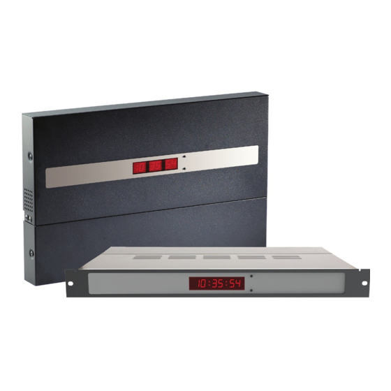
- Page 44 Valcom, Inc. P. 540-563-2000 5614 Hollins Road F. 540-362-9800 Roanoke, VA 24019 www.valcom.com Wireless System Setup On the right is a Wall/Surface Mount Master Clock with a built-in transmitter. On the right is a Rack Mount Master Clock and Remote Antenna/Transmitter.
- Page 45 Valcom, Inc. P. 540-563-2000 5614 Hollins Road F. 540-362-9800 Roanoke, VA 24019 www.valcom.com Web Interface - Log In 1. Password - There are two levels of passwords that will enable the user to access web interface features. The first level is User level programming, which includes features like setting the time, setting the date, and adding/editing events and schedule changes.
- Page 46 Valcom, Inc. P. 540-563-2000 5614 Hollins Road F. 540-362-9800 Roanoke, VA 24019 www.valcom.com Web Interface - Date/Time 1. Time - This field is where the current time is displayed. The time data should be received from an NTP server as standard or from a GPS receiver as an optional feature. If needed, the time can be edited manually by clicking within the field, typing the desired time into the field, and pressing the Change Time button.
- Page 47 6. Submit - This button, when pressed, saves and applies all the selections to the Master Clock. *sbdconfig is only available for 3200/3300 models of the Valcom Wired and Wireless digital clocks. ** Button-based configuration is only available for 3300 models of the Valcom Wired and Wireless digital clocks.
- Page 48 Valcom, Inc. P. 540-563-2000 5614 Hollins Road F. 540-362-9800 Roanoke, VA 24019 www.valcom.com Web Interface - DST (Daylight Saving Time) 1. Daylight Saving Time Selection - This drop down list gives four options for configuring Daylight Saving Time: • None - When this option is selected, Daylight Saving Time is not applied.
- Page 49 Valcom, Inc. P. 540-563-2000 5614 Hollins Road F. 540-362-9800 Roanoke, VA 24019 www.valcom.com Web Interface - Email Alerts 1. Email Recipient - This field is where the user name of the e-mail recipient is entered. Do not enter the domain and suffix. If the full address is johnsmith@domain.com, then johnsmith should be entered in this field.
- Page 50 Valcom, Inc. P. 540-563-2000 5614 Hollins Road F. 540-362-9800 Roanoke, VA 24019 www.valcom.com Web Interface - System Settings 1. User Password - This field allows the user to enter a new password for user-level programming. Users may view every tab, but cannot change every setting. The password must be entered once in the User Password field and once in the Confirm Password field, otherwise the password will not be changed when the Submit button is pressed.
- Page 51 Valcom, Inc. P. 540-563-2000 5614 Hollins Road F. 540-362-9800 Roanoke, VA 24019 www.valcom.com Web Interface - System Settings (Continued) 1. Bias Seconds - This field allows the user to add or subtract seconds from the time being sent to secondary clocks. This is useful for regions that offset their time from GMT by fractions of an hour (Central Australia, India, and Newfoundland, among others).
- Page 52 Valcom, Inc. P. 540-563-2000 5614 Hollins Road F. 540-362-9800 Roanoke, VA 24019 www.valcom.com Web Interface - Synchronization 1. Input Selection - This drop-down list allows the user to select which service signal the master clock will depend upon for accurate time. The options include:...
- Page 53 Valcom, Inc. P. 540-563-2000 5614 Hollins Road F. 540-362-9800 Roanoke, VA 24019 www.valcom.com Web Interface - Synchronization (Continued) 3. Clock #1 Circuit - This drop-down list allows the user to select the sync-wire output for master clock Sync-wire Circuit 1. The available output signals are:...
- Page 54 Valcom, Inc. P. 540-563-2000 5614 Hollins Road F. 540-362-9800 Roanoke, VA 24019 www.valcom.com Web Interface - IP Settings 1. Gateway IP Address* - This field allows the user to set the Gateway IP address for the master clock. 2. Subnet Mask* - This field allows the user to set the Subnet Mask for the master clock.
- Page 55 Valcom, Inc. P. 540-563-2000 5614 Hollins Road F. 540-362-9800 Roanoke, VA 24019 www.valcom.com Web Interface - NTP Servers 1. Retry Failed Server After - Under normal circumstances, if the master clock cannot get NTP time from the selected server on the list, it will attempt to get NTP time through another one of the listed addresses.
- Page 56 Valcom, Inc. P. 540-563-2000 5614 Hollins Road F. 540-362-9800 Roanoke, VA 24019 www.valcom.com Web Interface - IP Status NOTE: Everything in this tab reflects settings entered earlier or hard-wired into the master clock. This page is view-only. None of these settings can be changed from this tab.
- Page 57 Valcom, Inc. P. 540-563-2000 5614 Hollins Road F. 540-362-9800 Roanoke, VA 24019 www.valcom.com Web Interface - Clock Features 1. Display Format - This drop-down list allows the user to select whether they want the LED display on the master clock to display time in 12 or 24 hour mode. This does not affect the displays of secondary digital clocks.
- Page 58 Valcom, Inc. P. 540-563-2000 5614 Hollins Road F. 540-362-9800 Roanoke, VA 24019 www.valcom.com Web Interface - Database Maintenance 1. Upload Database - Sends the master clock settings, events, and schedules as a file to whichever device is accessing the master clock through the web interface. The file will be labeled “masterclockA.db”.
- Page 59 Voice-over-IP telephones, IP-operated cameras, or any IP device that can receive NTP or SNTP time protocol over a LAN. Valcom V-GPSA-NTP Master Clock models include the NTP server as a standard feature. Valcom also offers the NTP server as an optional upgrade to V-WMCA/V-GPSA/V-GPS-TX and V-MCS-CD Master Clocks. This upgrade is only available when selecting features for the master clock before purchase.
- Page 60 Valcom, Inc. P. 540-563-2000 5614 Hollins Road F. 540-362-9800 Roanoke, VA 24019 www.valcom.com Support - Frequently Asked Questions and Troubleshooting The master clock is not powering up. What do I do? Check the connection between the master clock and power source. The power cable should be correctly plugged into the power source and master clock.
- Page 61 Valcom, Inc. P. 540-563-2000 5614 Hollins Road F. 540-362-9800 Roanoke, VA 24019 www.valcom.com Support - Frequently Asked Questions and Troubleshooting Does this master clock convert time data to 2-wire 24-volt communication protocol? No. To convert time data to the 2-wire 24-volt communication protocol, the user must purchase a converter box by ordering part number SCB-100-000-1 My sync-wire secondary clocks do not seem to be getting the time shown on the master clock.
- Page 62 Valcom, Inc. P. 540-563-2000 5614 Hollins Road F. 540-362-9800 Roanoke, VA 24019 www.valcom.com Support - Frequently Asked Questions and Troubleshooting Why isn’t the Master Clock appearing on the IP Monitoring Software? Check the following: 1) Confirm that the computer running the IP Monitoring Software and the Master Clock are on the same subnet.
- Page 63 Valcom, Inc. P. 540-563-2000 5614 Hollins Road F. 540-362-9800 Roanoke, VA 24019 www.valcom.com Compliances FCC Statement: Information to the user (for U.S. only) This equipment has been tested and found to comply with the limits for a Class B digital device, pursuant to part 15 of the FCC Rules.
- Page 64 Warranty Valcom, Inc. warrants its products only to the original purchaser, for its own use, to be free from defects in materials and workmanship under conditions of normal use and service for a period of one year from the date of shipment.
Need help?
Do you have a question about the V-WMCA Series and is the answer not in the manual?
Questions and answers