Table of Contents
Advertisement
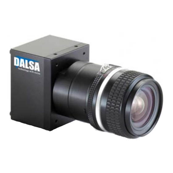
Spyder 3 Camera User's Manual
SG-10-01k80-00-R
SG-10-02k80-00-R
SG-10-01k40-00-R
SG-10-02k40-00-R
With the exception of the RoHS compliance information, the content in this manual also applies to
3-Jan-08
camera: SG-10-0xkx0-00-L and SG-10-0xkx0-12E models
the previous versions of the SG-10
03-032-10158-09
www.dalsa.com
Advertisement
Chapters
Table of Contents
Troubleshooting

Related Manuals for Dalsa Spyder 3 GigE SG-10-01k80-00-R


Summary of Contents for Dalsa Spyder 3 GigE SG-10-01k80-00-R
- Page 1 Spyder 3 Camera User’s Manual SG-10-01k80-00-R SG-10-02k80-00-R SG-10-01k40-00-R SG-10-02k40-00-R With the exception of the RoHS compliance information, the content in this manual also applies to 3-Jan-08 camera: SG-10-0xkx0-00-L and SG-10-0xkx0-12E models the previous versions of the SG-10 03-032-10158-09 www.dalsa.com...
- Page 2 Spyder 3 GigE User Manual © 2008 DALSA. All information provided in this manual is believed to be accurate and reliable. No responsibility is assumed by DALSA for its use. DALSA reserves the right to make changes to this information without notice. Reproduction of this manual in whole or in part, by any means, is prohibited without prior permission having been obtained from DALSA.
-
Page 3: Table Of Contents
4.3 Electrical Interface ...............................41 CCD Handling Instructions _________________________________________________ 44 5.1 Electrostatic Discharge and the CCD Sensor ........................45 5.2 Protecting Against Dust, Oil and Scratches........................45 5.3 Cleaning the Sensor Window............................46 Troubleshooting ________________________________________________________ 48 6.1 Troubleshooting _____________________________________________________ 49 6.2 Specific Solutions .................................51 DALSA 03-032-10158-09... - Page 4 A5 Error Handling ................................104 A6 Clearing Dark Current..............................106 Immediate read out mode (default, srm 2)....................107 Gate dark current clear mode (always on, srm 1) ..................107 Auto Mode (srm 0)............................108 EMC Declaration of Conformity______________________________________________ 114 Revision History ________________________________________________________ 116 Index _______________________________________________________________ 119 03-032-10158-09 DALSA...
-
Page 5: Introduction To The Spyder 3 Gige Camera
Chapter Contents 1.1 Camera Highlights ___________________________________________________ 6 Features.....................................6 Programmability ................................6 Description..................................6 Applications ..................................6 Models ....................................7 1.2 Camera Performance Specifications ________________________________________ 7 1.3 Image Sensor _______________________________________________________ 10 Sensitivity Mode and Pixel Readout ..........................10 Sensor Shift Direction................................12 1.4 Responsivity ________________________________________________________ 13 DALSA 03-032-10158-09... -
Page 6: Camera Highlights
FPN and PRNU. Description The Spyder 3 GigE camera is DALSA’s first GigE camera. With a GigE interface, you no longer need a frame grabber which means significant system cost savings. The Spyder 3 GigE is also DALSA’s first dual line scan camera. When operating in high sensitivity (dual line scan) mode, the Spyder 3 GigE camera has 3x the responsivity of a DALSA’s Spyder2 line scan camera. -
Page 7: Camera Performance Specifications
Antiblooming 100x 100x Gain Range ±10 ±10 Optical Interface Units Notes Back Focal Distance Lens mount adapters are M42x1 6.56±0.25 available. Contact Sales for more information. Sensor Alignment µm ±50 µm ±50 ±0.25 ° ±0.2 DALSA 03-032-10158-09... - Page 8 3264 Responsivity (single line) Random Noise rms 20.5 Dynamic Range ratio 500:1 1400 : 203:1 324:1 59:1 108:1 (Dual Line) Dynamic Range ratio 500:1 1400 : 203:1 324:1 59:1 108:1 (Single Line) FPN Global Uncorrected 52.8 169.6 Corrected 03-032-10158-09 DALSA...
- Page 9 Light Source: Broadband Quartz Halogen, 3250k, with 750 nm highpass filter installed. • Ambient test temperature 25 °C. • Unless otherwise specified, all values are referenced at 12 bit. • Exposure mode disabled. • Unless specified, dual line mode. Notes PRNU measured at 50% SAT. DALSA 03-032-10158-09...
-
Page 10: Image Sensor
Spyder 3 GigE User Manual 1.3 Image Sensor The camera uses DALSA’s dual line scan sensor. The camera can be configured to read out in either high or low sensitivity mode, tall pixel mode, and forward or reverse shift direction. - Page 11 Figure 5: Tall Pixel Mode Pixel Detail 14μm CCD Readout Shift Register Sensor 1 and 2 (28μm x 14μm) CCD Readout Shift Register In tall pixel mode, the camera uses a 28μmx14μm pixel and captures an image two times taller than in high or low sensitivity mode, creating a taller image. DALSA 03-032-10158-09...
-
Page 12: Sensor Shift Direction
Note: You can control the CCD shift direction through the serial interface. Use the software command scd to determine whether the direction control is set via software control or via the Camera Link control signal on CC3. Refer to the CCD Shift Direction section of this manual, page 57, for details. 03-032-10158-09 DALSA... -
Page 13: Responsivity
Spyder 3 GigE Spectral Responsivity. Nominal Gain 2500 High Sensitivity Mode 2250 Low Sensitivity Mode 2000 1750 1500 1250 1000 1000 1100 Wavelength (nm) Refer to section 1.3 Image Sensor for a description of high and low sensitivity modes. DALSA 03-032-10158-09... -
Page 14: Derating Curves
Spyder 3 GigE User Manual 1.5 Derating Curves Change in DC offset with Integration Time (12 Bit, 0dB Gain) 0.0002 0.0004 0.0006 0.0008 0.001 0.0012 Time (s) Change in DC Offset vs Temperature (12 Bit, 0dB Gain, Integration Time 200us) Temperature (°C) 03-032-10158-09 DALSA... - Page 15 Change in Noise vs Temperature (12 bit, 0dB Gain, Integration Time 200us) 19.50 19.00 18.50 DN RMS 18.00 17.50 17.00 16.50 16.00 Temperature (°C) Change in FPN vs Temperature (12 Bit, 0dB Gain, Integration Time 200us) Temperature (°C) DALSA 03-032-10158-09...
- Page 16 Spyder 3 GigE User Manual Change in PRNU (pk-pk) vs Temperature (12 Bit, 0dB Gain, Integration Time 200us) Temperature (°C) 03-032-10158-09 DALSA...
- Page 17 Spyder 3 GigE User’s Manual DALSA 03-032-10158-09...
-
Page 18: Setting Up The Camera
Fiber-Optic Interface Requirements ..........................22 2.3 Drivers: Overview ____________________________________________________ 22 High Performance Driver Mode............................22 Standard Driver Mode ...............................23 DALSA NetLink Universal IP Filter Driver Mode.......................23 Driver Comparison................................24 2.4 Camera Connectors ___________________________________________________ 24 TTL Inputs and Outputs ..............................27 LVDS Inputs and Outputs ..............................28 Programming the GPIO Connector............................28... -
Page 19: Installation Overview
QuickCam GUI. Install QuickCam driver. Open the Driver Installation Tool On the Windows task bar click Start , point to Programs—DALSA QuickCam— Tools — Launch Driver Installation Tool 2. If you are using an Intel PRO/1000 adapter a) On the... - Page 20 V to +15 V power supply. Open QuickCam. On the Windows task bar click , Start point Programs—DALSA QuickCam—DALSA QuickCam Confirm or enter your IP Address. In the Set Camera’s IP Adress dialog box, confirm or enter the camera’s IP Address.
-
Page 21: Equipment Recommendations
When you require more than one device on the same network or a camera-to-PC separation of more than 100 metres, you can use an Ethernet switch. Since the Spyder 3 GigE camera complies with the Internet Protocol, the camera should work with all DALSA 03-032-10158-09... -
Page 22: Drivers: Overview
In high-performance mode, the Spyder 3 GigE works with the High-Performance IP Device Driver to transfer data between cameras and PCs with very low, predictable latency at rates of up to 1 Gb/s (100 MB/s). The video data is streamed directly into PC 03-032-10158-09 DALSA... -
Page 23: Standard Driver Mode
PC. Note: For more information and instructions on installing the drive, refer to the Spyder 3 GigE Driver Manual. To view the manual, point to Programs → DALSA QuickCam → Documentation → Spyder 3 GigE Driver Manual Note: The DALSA NetLink IP Device Driver supports LOM implementations, but the PCI identification number for these may be different. -
Page 24: Camera Connectors
Spyder 3 GigE User Manual Note: For more information and instructions on installing the drive, refer to the Spyder 3 GigE Driver Manual. To view the manual, point to Programs → DALSA QuickCam → Documentation → Spyder 3 GigE Driver Manual Driver Comparison... -
Page 25: Ethernet Connector
Steady yellow indicates that the camera is ready for data transmission. Flashing yellow indicates that the camera is transmitting or receiving data. EMC Compliance In order to achieve EMC compliance, the Spyder 3 camera requires the use of shielded CAT5e or CAT6 Ethernet cables. DALSA 03-032-10158-09... -
Page 26: Power Connector
Note: Camera performance specifications are not guaranteed if your power supply does not meet these requirements. DALSA offers a power supply with attached 6’ power cable that meets the Spyder 3 GigE camera’s requirements, but it should not be considered the only choice. Many high quality supplies are available from other vendors. -
Page 27: Ttl Inputs And Outputs
1000 Ω 3.3V • Termination: 1000 Ω series • Input current: minimum 0 nA; maximum 2 mA • Input voltage: maximum of low 0.66 V; minimum of high 2.6 V • TTL inputs are 5V and 3.3V logic tolerant DALSA 03-032-10158-09... -
Page 28: Lvds Inputs And Outputs
QuickCam SDK. After you have installed the QuickCam program, refer to the QuickCam User’s Manual or the QuickCam help topic, GPIO Control, for more information on programming the connector. Refer to section 3 .1 QuickCam Interface for more 2 3 5 H information on installing QuickCam. 03-032-10158-09 DALSA... -
Page 29: Camera Led
μs 27.78 1000 1K 1 Tap 14.71 1000 1K 2 Tap 54.1 1000 2K 1 Tap 27.78 1000 2K 2 Tap twSync twSYNC_INT For exposure mode (3000*) 4 this value needs to be >3000ns other wise >100ns DALSA 03-032-10158-09... - Page 30 (MHz) LAN_clk_freq (MHz) num_taps 1 or 2 pixel_width 8 or 12 interline_delay (μs) 1k 1 tap 1600 1k 2 tap 1325 2k 1 tap 2275 2k 2 tap 1600 line_size 1024 or 2048 LAN Preparation Time 03-032-10158-09 DALSA...
- Page 31 LAN_Preparation_Time = (pkt_payload_size + pkt_header_size) / (LAN_clk_freq * 4) LAN Transfer Time LAN_Transfer_Time = (pkt_payload_size + pkt_header_size) / 125MB/s Overhead Delay Overhead_Delay can range from 5 to 6μs and is dependent upon the internal operations of your computer. DALSA 03-032-10158-09...
-
Page 32: Controlling The Camera
Installing and Running QuickCam and the QuickCam SDK ....................2 3 7 H Getting Help ..................................2 3 8 H 3.2 Using ASCII Commands ________________________________________________ 2 3 9 H 3.3 First Power Up Camera Settings __________________________________________ 2 4 0 H 03-032-10158-09 DALSA... -
Page 33: Quickcam Interface
3.1 QuickCam Interface Installing and Running the DALSA QuickCam GUI and the DALSA QuickCam SDK If you have not already installed the DALSA QuickCam GUI, refer to section 2 .1 2 4 4 H Installation Overview for details on installing and running the software. -
Page 34: Using Ascii Commands
At the OK> prompt, enter the ASCII command. Refer to Appendix A for details on all of the camera’s available ASCII commands. Press Enter. The camera responds with OK> if the command was successful or an error or warning message as appropriate. 03-032-10158-09 DALSA... - Page 35 Open the Port Communication tab. The Port Communication tab provides an ASCII interface. In order to comply with DALSA camera command protocol, you must send and receive as ASCII and ensure that the CR checkbox is checked (default). Figure 16: Port Communication Tab after Sending the h (Help) Command...
-
Page 36: First Power Up Camera Settings
8 bit output, 9600 baud rate, exposure mode 7. Notes: The FPN and PRNU coefficients are factory calibrated at a 5 kHz line rate and 0dB gain setting. While the factory setting baud rate is 9600, QuickCam sets the baud rate to 57600 at startup. 03-032-10158-09 DALSA... - Page 37 Spyder 3 GigE User’s Manual DALSA 03-032-10158-09...
-
Page 38: Optical, Mechanical, And Electrical Considerations
2 4 9 H Illumination..................................2 5 0 H Light Sources ..................................2 5 1 H Filters....................................2 5 2 H Lens Modeling ................................... 2 5 3 H Magnification..................................2 5 4 H 4.3 Electrical __________________________________________________________ 2 5 5 H 03-032-10158-09 DALSA... -
Page 39: Mechanical Interface
TO CCD IMAGING SURFACE Units : mm M3x0.5 THREAD DEPTH 5.0 (4X) 14.0 32.0 Figure 18: Spyder 3 GigE Heatsink Mechanical Dimensions 27.0 48.0 5.0 (2X) 14.0 18.5 29.0 39.5 50.0 32.0 60.0 3.2 THRU (2X) 2.0 (7X) DALSA 03-032-10158-09... -
Page 40: Optical Interface
The amount and wavelengths of light required to capture useful images depend on the particular application. Factors include the nature, speed, and spectral characteristics of objects being imaged, exposure times, light source characteristics, environmental and acquisition system specifics, and more. DALSA’s Web site, ttp://mv.dalsa.com/, 1 2 H provides an introduction to this potentially complicated issue. -
Page 41: Electrical Interface
The Spyder 3 GigE cameras have been designed for EMC compliance. The test setup has been verified to the following EMC standards: • CISPR-11:2004 • EN 55011:2003 • EN 61326:2002 To achieve EMC compliance, follow these specific guidelines: DALSA 03-032-10158-09... - Page 42 The EMC compliance is achieved with the use of shielded CAT5e or CAT6 Ethernet cables Shielded cable suppliers The following is a partial list of cable suppliers carrying cables that meet the compliance requirements: • http://www.systemax.com/divisions.htm • http://www.cablestogo.com • http://www.globalsources.com 03-032-10158-09 DALSA...
- Page 43 Spyder 3 GigE User’s Manual DALSA 03-032-10158-09...
-
Page 44: Ccd Handling Instructions
CCD Handling Instructions Chapter Contents 5.1 Electrostatic Discharge and the CCD Sensor___________________________________ 2 5 6 H 5.2 Protecting Against Dust, Oil and Scratches ___________________________________ 2 5 7 H 5.3 Cleaning the Sensor Window ____________________________________________ 2 5 8 H 03-032-10158-09 DALSA... -
Page 45: Electrostatic Discharge And The Ccd Sensor
Scratches diffract incident illumination. When exposed to uniform illumination, a sensor with a scratched window will normally have brighter pixels adjacent to darker pixels. The location of these pixels changes with the angle of illumination. DALSA 03-032-10158-09... -
Page 46: Cleaning The Sensor Window
5. Wipe the window carefully and slowly. 6. When cleaning long linear sensors, it may be easier to wipe along the width (i.e. as opposed to the length) of the sensor. 03-032-10158-09 DALSA... - Page 47 Spyder 3 GigE User’s Manual DALSA 03-032-10158-09...
-
Page 48: Troubleshooting
2 7 3 H Line Dropout..................................2 7 4 H Noisy Output..................................2 7 5 H Dark Patches..................................2 7 6 H Horizontal Lines or Patterns in Image ..........................2 7 7 H 6.3 Product Support _____________________________________________________ 2 7 8 H 03-032-10158-09 DALSA... -
Page 49: Troubleshooting
7 (5000 Hz line rate, internal Sync to trigger readout). After a user has saved settings, the camera powers up with the saved settings. If you change to an exposure mode that requires an external sync, ensure that you properly providing an external sync DALSA 03-032-10158-09... -
Page 50: Camera Operation And Test Patterns
To create an error report: Click the button on QuickCam toolbar. In the Save As dialog box: Select the location on your computer to save the file. In the File name text box, enter a name for the error report. 03-032-10158-09 DALSA... -
Page 51: Specific Solutions
Do not saturate the entire pad with solvent. 7. Wipe across the length of the window in one direction with the moistened end first, followed by the rest of the pad. The dry part of the pad should follow the moistened DALSA 03-032-10158-09... -
Page 52: Horizontal Lines Or Patterns In Image
If you have verified that your exposure time is consistent and patterns of low frequency intensity variations still occur, ensure that you are using a DC or high frequency light source. 03-032-10158-09 DALSA... -
Page 53: Product Support
Detailed description of problem please attach description with as much detail as appropriate encountered. In addition to your local DALSA representative, you may need to call DALSA Technical Sales Support: North America Europe Asia Voice:... -
Page 54: Spyder 3 Gige Ascii Commands
= integer value • = real number • = member of a set • = string • = tap id • = pixel column number • = pixel row number Example: to return the current camera settings <CR> 03-032-10158-09 DALSA... -
Page 55: Setting Baud Rate
If this occurs, values are clipped and the camera returns a warning message. Some commands may not be available in your current operating mode. The help screen displays NA in this case. DALSA 03-032-10158-09... - Page 56 0-2:0-4095 set sync frequency 300-68000 set system gain 0-2:0-65535 set sensitivity mode set upper threshold 0-4095 set video mode update gain reference verify temperature verify voltage write FPN coefficients write PRNU coefficients write user settings 03-032-10158-09 DALSA...
-
Page 57: A1 Sensor Output Format
F igure 6: Object Movement and Camera Direction 2 8 3 H Example using an Inverting Lens for an illustration of when you should use forward or reverse shift direction. Related Commands: s sm 1 8 H Example: scd 0 DALSA 03-032-10158-09... -
Page 58: A1.3 Setting The Bit Depth And Data Mode
To obtain the current value of the exposure mode, use the command g et sem . g cp 2 2 H 2 3 H Related Commands: s sf s et 2 4 H 2 5 H Example: sem 3 03-032-10158-09 DALSA... - Page 59 + line transfer time. Example 1: Exposure Time less than Line Period Programmable Period ( command) Programmable Period Exposure Time Readout Readout Exposure Time Line Period Line Period Programmable Period (ssf command) Programmable Period CR=Charge Reset DALSA 03-032-10158-09...
- Page 60 In this mode, the falling edge of EXSYNC sets the line period and the rising edge of PRIN sets the start of exposure time. Figure 20: EXSYNC controls Line Period and PRIN controls Exposure Time Line Period Line Period Line Period Readou Readou EXSYNC PRIN cr=Charge Reset 03-032-10158-09 DALSA...
- Page 61 Mode 8: Maximum Line Rate, Programmable Exposure Time In this mode, the exposure time is set internally with a maximum line rate. Figure 23: Mode 8 Timing Programmable Period Programmable Period Readout CR Exposure Time Readout CR Exposure Time Frame Period Frame Period CR=Charge Reset DALSA 03-032-10158-09...
-
Page 62: Setting The Readout Mode
EXSYNC is skipped and, therefore, the output will be at least twice as bright. • This value is saved with the camera settings. • This value may be viewed using either the gcp command or the get srm command. Related Commands: sem, ssf Example: srm 0 03-032-10158-09 DALSA... -
Page 63: Setting The Line Rate
*The exposure time range is based on the current line rate. • To determine the maximum exposure time allowed for the current line rate, use the command get ger . Related Commands: s sf 3 4 H 3 5 H Example: set 400.5 DALSA 03-032-10158-09... -
Page 64: A1.5 Configuring The Gpio Connector
3 6 H 3 7 H sgo i where i is the output signal. • If you enter an invalid configuration, an error message is returned. Related Commands: s gi 3 8 H Example: sgo 0 1 03-032-10158-09 DALSA... - Page 65 4 0 H • If you enter an invalid configuration, an error message is returned. Related Commands: s go 4 1 H Example: sgi 3 1 sgs p i sgs 0 0 DALSA 03-032-10158-09...
-
Page 66: A2 Data Processing
5 0 H 5 1 H 5 2 H 5 3 H 5 4 H 5 5 H 5 6 H 5 7 H Example: roi 10 1 50 1 03-032-10158-09 DALSA... -
Page 67: A2.2 Analog And Digital Signal Processing Chain
6 1 H introduced into the video path to ensure that the A/D is functioning properly. The analog offset should be set so that it is at least 3 times the rms noise value at the current gain. Digital Processing DALSA 03-032-10158-09... - Page 68 Gain value in a range from –10 to +10 dB. Notes: • To return the current analog gain setting, use the command g cp g et sag 6 9 H 7 0 H Example: sag 0 5.2 Related Commands: c cg 7 1 H Calibrating Camera Gain 03-032-10158-09 DALSA...
- Page 69 7 2 H 7 3 H 7 4 H s sg 0 4096 7 5 H Example: ccg 2 0 3040 Related Commands: s sg 7 6 H 7 7 H Setting Analog Offset DALSA 03-032-10158-09...
- Page 70 Purpose: Sets the analog offset. The analog offset should be set so that it is at least 3 times the rms noise value at the current gain. DALSA configures the analog offset for the noise at the maximum specified gain and as a result you should not need to adjust the analog offset.
-
Page 71: Flat Field Correction
White paper is often not sufficient because the grain in reference does not the white paper will distort the correction. White plastic or white ceramic will lead to extend the full field of view of the camera, better balancing. the camera will send a warning. DALSA 03-032-10158-09... - Page 72 When 6.25% of pixels from a single row within the region of interest are clipped, flat field correction results may be inaccurate. • Correction results are valid only for the current analog gain and offset values. If you change these values, it is recommended that you recalculate your coefficients. 03-032-10158-09 DALSA...
- Page 73 . You should see close to zero output. Perform PRNU calculation next to determine the multiplication factors required to bring each pixel to the required value (balance target) for Perform PRNU calculation flat, white output. 1. Place a white reference in front of the camera. 2. Verify that the output signal level is within range by issuing the command or . If the signal level is too low, increase your light level, adjust the analog gain ( ) or use the automated algorithm ccg i 0 i DALSA recommends a target value of about 80% of saturation. If you change the gain, FPN coefficients should be recalculated. 3. Issue the command . The camera will respond with OK>( if no error occurs). 4. After the calculation is complete, you can save these settings to non‐volatile memory so they will be remembered after power‐down and direction change. To do so, issue the commands and wus. . Enable the coefficients using the command, epc 1 1 . Note: All commands listed above are described in detail in the following sections in the order that they should be performed.
-
Page 74: Digital Signal Processing
Sets an individual pixel’s FPN coefficient. Syntax sfc x i Syntax Elements: The pixel number from 1 to sensor pixel count . Coefficient value in a range from 0 to 2047 (12 bit LSB). Example: sfc 10 50 03-032-10158-09 DALSA... - Page 75 See the s sg 8 8 H previous section for details on the command. s sg 8 9 H Related Commands: s sg 9 0 H Example: sdo 0 100 DALSA 03-032-10158-09...
- Page 76 This algorithm is useful for achieving uniform output across multiple cameras. This algorithm is useful for achieving uniform output across multiple cameras by first adjusting analog gain and then performing PRNU calibration. This algorithm is recommended 03-032-10158-09 DALSA...
- Page 77 2 9 0 H PRNU and FPN Coefficients for details. • The QuickCam software that ships with the Spyder 3 GigE camera has a flat field correction wizard. For easy flat field correction, use the wizard located on the DALSA 03-032-10158-09...
- Page 78 It is useful for systems that process 8 bit data but want to take advantage of the camera’s 12 bit digital processing chain. You should try to make your darkest pixel in the scene equal to zero. Syntax: ssb t i 03-032-10158-09 DALSA...
- Page 79 Gain setting. The gain ranges are 0 to 65535 . The digital video values are multiplied by this value where: Digital Gain= 4096 Use this command in conjunction with the command. s sb 1 0 1 H Related Commands: s sb 1 0 2 H Example: ssg 1 15 DALSA 03-032-10158-09...
-
Page 80: Returning Calibration Results And Errors
Returning PRNU Coefficients Purpose: Returns a pixel’s PRNU coefficient value in DN (12 bit LSB) Syntax: gpc i Syntax Elements: The pixel number to read in a range from 1 to sensor pixel count . Example: gpc 10 03-032-10158-09 DALSA... -
Page 81: A2.3 End-Of-Line Sequence
4 bit counter LSB justified Counter increments by 1. Use this value to verify that every line is output Line sum (7…0) Line sum (15…8) Use these values to help calculate line average and gain Line sum (23…16) Line sum (31…24) DALSA 03-032-10158-09... -
Page 82: Setting Thresholds
Upper threshold limit in range from 0 to 4095 . • Notes: LVAL is not high during the end-of-line statistics. Related Commands: • e ls s ut 1 0 7 H 1 0 8 H Example: slt 1024 03-032-10158-09 DALSA... -
Page 83: A3 Saving And Restoring Settings
To save the current pixel coefficients, use the command and wfc. • To restore the last saved pixel coefficients, use the command Current Session Settings These are the current operating settings of your camera. To save these settings to non- volatile memory, use the command DALSA 03-032-10158-09... -
Page 84: A3.1 Saving And Restoring Prnu And Fpn Coefficients
3 = Coefficient set three 4 = Coefficient set four Example: lpc 0 Resetting the Current Pixel Coefficients Purpose: Resets the current pixel coefficients to zero. This command does not reset saved coefficients. Syntax: Notes: The digital offset is not reset. 03-032-10158-09 DALSA... -
Page 85: A3.2 Rebooting The Camera
The following tables show each available test pattern. Syntax: svm i Syntax Elements: Video. 12 bit ramp test pattern. 2 tap model 1 tap model 8 bit step test pattern. 2 tap model DALSA 03-032-10158-09... -
Page 86: A4.1.1 Ethernet Test Pattern
The following table shows the ethernet test pattern available through the QuickCam GUI. Availability: Under the Diagnostics tab in the Test Patter drop-down list. Ethernet. 2 tap model 1 tap model 03-032-10158-09 DALSA... -
Page 87: A4.2 Returning Video Information
To return the current setting, use the command or g cp g et 1 1 1 H 1 1 2 H Related Commands: c pa 1 1 3 H 1 1 4 H 1 1 5 H 1 1 6 H Example: css 1024 DALSA 03-032-10158-09... -
Page 88: A4.3 Temperature Measurement
(typically within 10%). The measurement should not be used to set the applied voltage to the camera but only used as a test to isolate gross problems with the supply voltage. 03-032-10158-09 DALSA... -
Page 89: A4.5 Camera Frequency Measurement
2 = green (camera is operating correctly) 5 = flashing green (camera is performing a function) 6 = flashing red (fatal error) • Notes: Refer to section 2 .5 Camera LED for more information on 2 9 5 H the camera LED DALSA 03-032-10158-09... -
Page 90: A4.7 Returning Camera Settings
Set using the srm command. Current exposure mode Exposure Mode: value set with the s em 1 2 1 H command. See section A 1.4 Exposure Mode, 3 0 0 H Readout Mode, Line Rate and Exposure Time for details. 03-032-10158-09 DALSA... - Page 91 States whether FPN FPN Coefficients: coefficients are on or off. Set with the e pc 1 2 7 H command. Refer to section A 2.2 Analog 3 0 8 H and Digital Signal Processing Chain for details. DALSA 03-032-10158-09...
- Page 92 3 1 4 H Signal Processing Chain for details. Digital offset settings Digital Offset: set with the s do 1 3 4 H command. See section A 2.2 Analog and Digital 3 1 5 H Signal Processing Chain for details. 03-032-10158-09 DALSA...
-
Page 93: Returning Camera Settings With Get Commands
Returns the current GPIO configuration. get dgc Returns pixel coefficients without formatting. get dpc x1 x2 Returns whether the end-of-line statistics are turned off or get els 0 : Off 1 : On DALSA 03-032-10158-09... - Page 94 Returns the analog offset for the tap indicated. get sao t = 0 for all taps or 1 to 2 for individual tap selection. Returns the horizontal binning factor. get sbh Returns the speed of camera serial communication port. get sbr 03-032-10158-09 DALSA...
- Page 95 0 = disabled 1 = TTL 2 = LVDS Returns the current output signal setting for the output get sgo number specified where: 0 = disabled 1 = TTL 2 = LVDS Returns the current lower threshold value. get slt DALSA 03-032-10158-09...
- Page 96 Returns whether PRNU coefficients have been saved. get wpc 0 = No PRNU coefficients saved 1 = Pixel coefficients have been saved Returns whether user settings have been saved. get wus 0 = No user settings saved 1 = User settings have been saved 03-032-10158-09 DALSA...
- Page 97 = Calibration target value in a range from 1024 to 4055 DN (12 bit LSB). correction calibrate prnu Performs PRNU calibration and eliminates the difference in responsivity between the most and least sensitive pixel creating a uniform response to light. DALSA 03-032-10158-09...
- Page 98 GPIO connector. display pixel coeffs Displays the pixel coefficients in the x1 x2 order FPN, PRNU, FPN, PRNU, … x1 = Pixel start number x2 = Pixel end number in a range from 1 to 1024 or 2048 03-032-10158-09 DALSA...
- Page 99 = pixel number to read in a range from 1 – sensor pixel count . get signal frequency Reads the requested Camera Link control frequency. 1 = EXSYNC frequency 2 = Spare 3 = Direction 4 = Spare DALSA 03-032-10158-09...
- Page 100 0 for all taps. i = Offset value in a range from 0 to 255 (12-bit LSB). Offset increases with higher values. set binning horizontal Sets the horizontal binning value. Available values are 1 and 2 . 03-032-10158-09 DALSA...
- Page 101 ( h command) for allowable range. set fpn coeff Set the FPN coefficient. x =pixel number within the range 1 to sensor pixel count . i = FPN value within the range 0 to 2047 (12-bit LSB). DALSA 03-032-10158-09...
- Page 102 Set the digital gain. t = tap selection, either 1 to 2 , or 0 for all taps i = Digital gain in a range from 0 to 65535 . The digital video values are multiplied by this number. 03-032-10158-09 DALSA...
- Page 103 EEROM where i is: 1 = PRNU coefficient set one 2 = PRNU coefficient set two 3 = PRNU coefficient set one 4 = PRNU coefficient set two write user settings Write all of the user settings to EEROM. DALSA 03-032-10158-09...
-
Page 104: A5 Error Handling
Not an element of the set of possible values. E.g., Baud Rate · Outside the range limit Error 05: Command Command is valid at this level of access, but not effective. Eg line rate unavailable in this when in smart EXSYNC mode mode> 03-032-10158-09 DALSA... - Page 105 Cannot calibrate a tap that is not part of the region of interest. calibrate - tap outside ROI> Error 09: The Indicates that the camera has shut itself down to prevent damage from camera's further overheating. temperature exceeds the specified operating range> DALSA 03-032-10158-09...
-
Page 106: A6 Clearing Dark Current
Frequency Mode Readout Mode Figure 26: Gate Dark Current Clear Table 16. Transition Frequencies Model Dark Current Clear to Immediate Readout to Immediate Readout Dark Current Clear Transition Transition SG-10-01K40-00-R 13.6KHz 16.4KHz SG-10-01K80-00-R 25.1KHz 30.4KHz SG-10-02K40-00-R 7.05KHz 8.52KHz 03-032-10158-09 DALSA... -
Page 107: Immediate Read Out Mode (Default, Srm 2)
The actual exposure time will not be altered. Table 18. Model Exposure Delay and Max Exposure Time in Auto Mode SG-10-01K40-00-R 27.5µs SG-10-01K80-00-R 14.75 µs SG-10-02K40-00-R 53.1 µs SG-10-02K80-00-R 27.5 µs DALSA 03-032-10158-09... -
Page 108: Auto Mode (Srm 0)
T able 18 3 2 2 H Note: DALSA recommends Auto mode for most users. For information on artifacts that may be experienced while using this mode, see the Artifacts section below. Please note: The graphic below explains the relationship between the following tables and the preceding . - Page 109 Immediate Readout state SRM 2, Immediate Readout Mode. Operating Region Time Period Operating Mode Refer to F igure 26. 3 2 7 H Dark Current Dump state Immediate Readout state Dark Current Dump to Immediate Readout (T < #) DALSA 03-032-10158-09...
- Page 110 3 2 9 H Immediate Readout state Dark Current Dump state Immediate Readout state SRM 2, Immediate Readout Mode. Operating Region Time Period Operating Mode Refer to F igure 26. 3 3 0 H Dark Current Dump state Immediate Readout state 03-032-10158-09 DALSA...
- Page 111 Spyder 3 GigE User’s Manual Dark Current Dump to Immediate Readout (T < #) Dark Current Dump to Immediate Readout (T > #) DALSA 03-032-10158-09...
- Page 112 3 3 1 H Immediate Readout state Dark Current Dump state SRM 0, Auto Mode. Operating Region Time Period Operating Mode Refer to F igure 26. 3 3 2 H Dark Current Dump state Immediate Readout state Dark Current Dump state 03-032-10158-09 DALSA...
- Page 113 EXSYNC is skipped and, therefore, the output will be at least twice as bright. • This value is saved with the camera settings. • This value may be viewed using either the gcp command or the get srm command. Related Commands: sem, ssf Example: srm 0 DALSA 03-032-10158-09...
-
Page 114: Emc Declaration Of Conformity
73/23/EEC and the EMC Directive 89/336/EEC and carries the CE mark accordingly. Place of Issue Waterloo, ON, CANADA Date of Issue August 2006 Name and Signature Hank Helmond Quality Manager, DALSA Corp. of authorized person This Declaration corresponds to EN 45 014. 03-032-10158-09 DALSA... - Page 115 Spyder 3 GigE User’s Manual DALSA 03-032-10158-09...
-
Page 116: Revision History
QuickCam GUI. Section 2.2 Equipment Recommendations: Ethernet shielded cable information added. Section 2.4 Camera Connectors: Ethernet shielded cable information added. Section 3.3 First Power Up Camera Settings: 500 Hz line rate changed to 5000 03-032-10158-09 DALSA... - Page 117 -Get scd description, page 95, revised to include the following: When scd 2 is selected, the following is returned: 2 = External direction control: currently forward (CC3 is high). 3 = External direction control: currently reversed (CC3 is low). DALSA 03-032-10158-09...
- Page 118 Intel LAN on the motherboard (LOM) chips. -Note added to the front cover stating that the information in this manual also applies to the previous versions of the SG-10 camera, with the exception of the RoHS compliance information. 03-032-10158-09 DALSA...
-
Page 119: Index
40 flat field correction errors, 80 dark calibration. See flat field performing, 73 correction restrictions, 71 Dark Current results, 80 Clearing, 106 dark patches, 51 coefficient, 74 data rate, 8 correction, 74 debugging, 48 derating curves, 14 DALSA 03-032-10158-09... - Page 120 108 drawing, 39 default, 107 specifications, 8 gate dark current clear, 107 mode immediate, 107 setting, 62, 113 performance, 23 rebooting, 85 standard, 23 region of interets (ROI) Universal IP Filter Driver Mode, setting, 66 03-032-10158-09 DALSA...
- Page 121 54 settings factory, 36 restoring, 83 returning, 90, 93 video data, 88 saving, 83 voltage shielded cables measurement, 88 compliance, 41 shift direction, 12 standard mode, 23 statistics, 87 warning messages, 104 status LED, 29 subtracting background, 78 DALSA 03-032-10158-09...
Need help?
Do you have a question about the Spyder 3 GigE SG-10-01k80-00-R and is the answer not in the manual?
Questions and answers