Table of Contents
Advertisement
Quick Links
Advertisement
Table of Contents
Troubleshooting

Related Manuals for Dalsa Spyder2 S2-1-40 Series


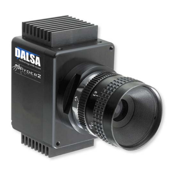
Summary of Contents for Dalsa Spyder2 S2-1-40 Series
- Page 1 Spyder2 Camera User’s Manual S2-1x-xx40 11-May-05 03-32-10091-04 www.dalsa.com...
- Page 2 Spyder2 User’s Manual © 2005 DALSA. All information provided in this manual is believed to be accurate and reliable. No responsibility is assumed by DALSA for its use. DALSA reserves the right to make changes to this information without notice. Reproduction of this manual in whole or in part, by any means, is prohibited without prior permission having been obtained from DALSA.
-
Page 3: Table Of Contents
3.16 Setting and Reading PRNU Coefficients ........................34 3.17 Test Patterns and End of Line Sequence ........................34 3.18 Monitoring the Camera .............................35 3.19 Rebooting the Camera...............................37 3.20 Setting the Pre-trigger ..............................37 Optical, Mechanical, and Thermal Considerations_________________________________ 39 4.1 Mechanical Interface..............................39 CCD Handling Instructions _________________________________________________ 45 03-32-10091-04 DALSA... - Page 4 Networking Mode, Error Handling and Command List ______________________________ 57 B1 Networking Mode.................................57 B2 Error Handling ................................59 B3 Camera Parameter Screen ............................63 B4 All Available Commands ..............................65 EMC Declaration of Conformity______________________________________________ 71 Revision History ________________________________________________________ 73 Index _______________________________________________________________ 75 03-32-10091-04 DALSA...
-
Page 5: Introduction To The Spyder2 Line Scan Camera
Cabling and interface are simplified with the Camera Link high-speed serial standard. The camera is sensitive, but still provides quiet, uniform output thanks to CDS (correlated double sampling) and embedded flat-field correction algorithms. Gain and offset are fully programmable and the camera can output test 03-32-10091-04 DALSA... -
Page 6: Image Sensors
1.3 Camera Performance Specifications Feature / Units Value Notes Specification Sensor Features Resolution pixels 512/1024/2048 Pixel Size µm 14 x 14 Output Format (# of taps) Optical Interface Units Notes Back Focal Distance Sensor die to 6.78 ±250µm mounting plate 03-32-10091-04 DALSA... - Page 7 35 (1024) 18 (2048) Data Rate Data Format 8 bit 10 bit 8 or 10 bit user selectable. Nominal Gain Range Dynamic Range DN:DN 330:1 500:1 Pixel Response Non- Uniformity (PRNU) uncorrected corrected (ECD/ECE) 1.2/1.5 DN p-p uncorrected corrected 03-32-10091-04 DALSA...
- Page 8 • Nominal Gain setting, unless specified • Light Source: Broadband Quartz Halogen, 3250K, with 750nm cutoff filter installed • Ambient test temperature: 25°C. • De-rating specifications for temperature range from 0°C to 50°C. 03-32-10091-04 DALSA...
- Page 9 Spyder2 User’s Manual Figure 2: Spyder2 Responsivity Spyder2 Responsivity@10dB 14µm pixels 400 500 1000 Wavelength (nm) 03-32-10091-04 DALSA...
- Page 10 Spyder2 User’s Manual 03-32-10091-04 DALSA...
-
Page 11: Camera Hardware Interface
• High-density 26-pin MDR26 connector for Camera Link control signals, data signals, and serial communications. Refer to Figure 4: MDR26 Connector for pin descriptions. • 6-pin Hirose connector for power. Refer to page 14 for pin descriptions. 03-32-10091-04 DALSA... -
Page 12: Led Status Indicator
A Base Configuration uses 1 MDR26 connector and 1 Channel Link chip. The main characteristics of the Base Configuration are: • Ports supported: A, B, C • Serializer bit width: 28 • Number of chips: 1 • Number of MDR26 connectors: 1 03-32-10091-04 DALSA... -
Page 13: Data Connector
Frame Grabber Signal inner shield inner shield Xclk- Xclk+ SerTC+ SerTC- SerTFG- SerTFG+ CC1- CC1+ CC2+ CC2- CC3- CC3+ CC4+ CC4- inner shield inner shield Unused pairs should be terminated in 100 ohms at both ends of the cable. 03-32-10091-04 DALSA... -
Page 14: Input Signals
11, 24 Spare 12, 25 See Appendix B for the complete DALSA Camera Link configuration table, and refer to the DALSA Web site, vfm.dalsa.com, for the official Camera Link documents. Digital Data The camera digitizes internally to 10 bits and outputs either all 10 bits or the most significant 8 bits in LVDS format on the Camera Link connector. -
Page 15: Power Connector
Incorrect voltages will damage the camera. Protect the camera with a fast-blow fuse between power supply and camera. Visit the www.dalsa.com Web site for a list of companies that make power supplies that meet the camera’s requirements. The companies listed should not be considered the only choices. -
Page 16: Timing
Spyder2 User’s Manual 2.3 Timing Figure 5. Spyder2 Overview Timing Showing Input and Output Relationships Figure 6. Spyder2 Fixed (Programmed) Integration Timing with External EXSYNC 03-32-10091-04 DALSA... - Page 17 The nominal time that the photo sites are 2,000+/-200 integrating. Clock synchronization will lead to integration time jitter, which is shown in the specification as +/- values. The user should command times greater than these to ensure proper charge 03-32-10091-04 DALSA...
- Page 18 Failure to meet this requirement may result in blooming in the Horizontal Shift Register. *SMART EXSYNC refers to exposure mode 4. Refer to section 3.9 Setting Line Rate and Exposure Mode for further information on exposure modes. 03-32-10091-04 DALSA...
-
Page 19: Software Interface: How To Control The Camera
To generate this list, send the command to the camera. Retrieving Camera Settings To read current camera settings, send the command . For an explanation of the camera parameter screen, see section B3 Camera Parameter Screen on page 63. 03-32-10091-04 DALSA... -
Page 20: Command Format
For example, the analog gain value can be set to –5db in calibrated mode and 6dB in uncalibrated mode. When switching between calibrated and uncalibrated modes, the camera automatically uses the corresponding value. 03-32-10091-04 DALSA... -
Page 21: Startup
To save all current pixel coefficients to EEROM, use the command • To restore the last saved user settings and the FPN and PRNU coefficients, use the command Figure 8: Saving and Restoring Settings Factory User Settings Settings wus,rus, command commands Current Session 03-32-10091-04 DALSA... -
Page 22: Setting Baud Rate
Syntax Elements: Video mode to use. Allowable values are: 0 Uncalibrated video, deactivated video correction 1 Calibrated video, activated video correction 2 Test pattern right Notes: • To obtain the current video mode, use the command Example svm 1 03-32-10091-04 DALSA... -
Page 23: Setting Line Rate And Exposure Mode
Exposure Mode on the following page for details. Then, when applicable, use the commands (mode 2 only) to set the line rate and/or (mode 2 or 6), to set the exposure time. Refer to Setting Line Rate and Setting Exposure Time below for details. 03-32-10091-04 DALSA... -
Page 24: Setting The Exposure Mode
(h command). Notes: • To read the current exposure time, use the command • If you enter an invalid exposure time, the valid range of values will be displayed. Related Commands: sem, ssf Example: set 2100 03-32-10091-04 DALSA... -
Page 25: Setting A Region Of Interest
Min, Max, and Mean statistics generated at the end of the line output. • Notes: If you do not specify a pixel range to display, the line output will display all sensor pixels on screen. 03-32-10091-04 DALSA... - Page 26 If a region of interest has been set using the roi command, the Min, Max, and Mean statistics at the end of the line output include statistics for the region of interest only. • Values returned are in DN. Example: gl 10 20 03-32-10091-04 DALSA...
-
Page 27: Optimizing Offset Performance
When subtracting a digital value from the digital video signal the output can no longer reach its maximum. Use command to correct for this. See section 3.13 Setting Gains for details on the ssg command. Example: ssb 0 20 03-32-10091-04 DALSA... - Page 28 8 bit: 1 to 100DN 10 bit: 4 to 400DN See section 3.11 Returning Video Information for more information on line averages. Notes: • This command sets offset in uncalibrated mode (svm 0). Example: cao 0 100 03-32-10091-04 DALSA...
-
Page 29: Setting Gains
Note: This function requires a constant light input while it executes. This feature is beneficial for achieving a common output level for multiple cameras in a system. 03-32-10091-04 DALSA... -
Page 30: How To Calibrate The Camera
The calibration algorithm is performed in two steps. The fixed offset (FPN) is determined first by performing a calibration without any light. This calibration determines exactly how much offset to subtract per pixel in order to obtain flat output when the CCD is not exposed. 03-32-10091-04 DALSA... - Page 31 Dark calibration is used to remove the fixed analog offset from the video path. It is recommended you repeat the calibration when a temperature change greater than 10°C occurs. To perform dark calibration: Stop all light from entering the camera. (Tip: cover lens with a lens cap.) 03-32-10091-04 DALSA...
- Page 32 Place a white reference in front of the camera. Verify that output signal level is within range by issuing the command (valid range is 128-254). If signal level is too low or too high, adjust the gain using the command 03-32-10091-04 DALSA...
-
Page 33: Setting And Reading Fpn Coefficients
The pixel number from 1 to the pixel count. Coefficient value in a range from 0 to 127. Example: sfc 10 50 To read the FPN coefficient, use the command: Syntax: gfc i Syntax Elements: The pixel number to read. Example: gfc 10 03-32-10091-04 DALSA... -
Page 34: Setting And Reading Prnu Coefficients
By ensuring these values consistently toggle between "aa" and "55", you can verify cabling 5’s (i.e. no stuck bits) A’s 4 bit counter LSB justified Counter increments by 1. Use this value to verify that every line is output 03-32-10091-04 DALSA... -
Page 35: Monitoring The Camera
Lengthy operation in progress Steady GREEN Healthy Note: When more than one condition is active, the LED indicates the condition with the highest priority. Error and warning states are accompanied by corresponding messages further describing the current camera status. 03-32-10091-04 DALSA... -
Page 36: Temperature Measurement
If they are within the proper range, the camera returns OK>. Otherwise the camera returns an error message. Note that the voltage measurement feature of the camera provides only approximate results (typically within 10%). They should not be used to set 03-32-10091-04 DALSA... -
Page 37: Rebooting The Camera
Previously saved pixel coefficients are also restored. 3.20 Setting the Pre-trigger A pre-trigger may be required for some frame grabbers. To set the pre-trigger, use the command: Syntax: sp i Syntax Elements: Pretrigger value from 0 to 15. Example: sp 10 03-32-10091-04 DALSA... - Page 38 Spyder2 User’s Manual 03-32-10091-04 DALSA...
-
Page 39: Optical, Mechanical, And Thermal Considerations
±10°C. Note: Upon initial power-up the front plate camera temperature is near ambient. It is recommended to perform flat-field correction once the camera gets within 10°C of its 03-32-10091-04 DALSA... - Page 40 M3x0.5 - 6H (4X) 42.0 (2x) R4.0 (4X) 6.0 DEEP M42x1 - 6H R1.6 (2x) 57.0 (2x) 65.0 32.5 M3x0.5 - 6H (4X) 9.0 (2X) 32.0 (2X) 5.0 DEEP 4.0 (2x) 4.0 (2x) 25.0 40.8 All units in mm. CALIBRATION STICKER 03-32-10091-04 DALSA...
-
Page 41: Optical Interface
Factors include the nature, speed, and spectral characteristics of objects being imaged, exposure times, light source characteristics, environmental and acquisition system specifics, and more. DALSA’s web site, vfm.dalsa.com, provides an introduction to this potentially complicated issue. See “Radiometry and Photo Responsivity”... -
Page 42: Light Sources
• LED light sources are relatively inexpensive, provide a uniform field, and longer life span compared to other light sources. However, they also require a camera with excellent sensitivity, such as DALSA’s Spyder2 camera. • Halogen light sources generally provide very little blue relative to IR. - Page 43 Example: An acquisition system has a 512 x 512 element, 10µm pixel pitch area scan camera, a lens with an effective focal length of 45mm, and requires that 100µm in the object space correspond to each pixel in the image sensor. Using the preceding equation, the object distance must be 450mm (0.450m). 03-32-10091-04 DALSA...
- Page 44 Spyder2 User’s Manual 03-32-10091-04 DALSA...
-
Page 45: Ccd Handling Instructions
Using rubber fingercots and rubber gloves can prevent oil contamination. However, the friction between the rubber and the window may produce electrostatic charge that may damage the sensor. To avoid ESD damage and 03-32-10091-04 DALSA... -
Page 46: Cleaning The Sensor Window
5. Wipe the window carefully and slowly. 6. When cleaning long linear sensors, it may be easier to wipe along the width (i.e. as opposed to the length) of the sensor. 03-32-10091-04 DALSA... -
Page 47: Troubleshooting
2 (5kHz line rate, and internal Sync to trigger readout). After a user has saved settings, the camera powers up with the saved settings. Note, a warning appears when switching to exposure mode requiring external signals if external signals are not present (EXSYNC or PRIN). 03-32-10091-04 DALSA... -
Page 48: Troubleshooting Using The Serial Interface
The test pattern is a ramp from 0 to 255DN, then starts svm 2 at 0 again. Use the test pattern to verify the proper timing and connections between the camera and the frame grabber. 03-32-10091-04 DALSA... -
Page 49: Verify Voltage
The camera enters a warning state when any of the camera's continuously running monitoring tasks detects a failure. Use the command to display the status of all the defined monitory tasks (if no parameter is passed) and/or to enable/disable specific monitoring tasks. 03-32-10091-04 DALSA... -
Page 50: Specific Solutions
If data bits seem to be stuck or do not change, check that the camera is not saturated by preventing light from entering. To verify the data path integrity, check the levels of the 2 test pattern pixels (first 2 pixels following the last End-of-line pixel. You may need to turn 03-32-10091-04 DALSA... -
Page 51: Horizontal Lines Or Patterns In Image
If you have verified that your exposure time is consistent and patterns of low frequency intensity variations still occur, ensure that you are using a DC or high frequency light source. 03-32-10091-04 DALSA... -
Page 52: Product Support
Results when you run the get_camera_parameter command Detailed description of problem please attach description with as much detail as appropriate encountered. In addition to your local DALSA representative, you may need to call DALSA Technical Sales Support: North America Europe Asia 519-886-6000... -
Page 53: Camera Link™ Reference
The Channel Link technology is integral to the transmission of video data. Image data and image enable signals are transmitted on the Channel Link bus. Four enable signals are defined as: • FVAL—Frame Valid (FVAL) is defined HIGH for valid lines. • LVAL—Line Valid (LVAL) is defined HIGH for valid pixels. 03-32-10091-04 DALSA... -
Page 54: A1 Camera Link™ Configuration Table
A1 Camera Link™ Configuration Table The following table provides tap reconstruction information. DALSA is working with the machine vision industry to use this table as the basis for auto configuration. Visit the http://vfm.dalsa.com Web site and view the DALSA Camera Link Implementation Road Map document, 03-32-00450, for further details. - Page 55 <0,1,2,3…> Column Color Offset <0,1,2,3…> Row Binning Factor <1,2,3 or 1|2|3> Column Binning Factor <1,2,3 or 1|2|3> Pretrigger Pixels <0,1,2…or 0..15> Pretrigger Lines <0,1,2.. or 0..15> 0...15 Line Time Minimum <xx µs> 512: 15.38 1024: 28.57 2048: 55.56 03-32-10091-04 DALSA...
- Page 56 BAUD Rate <9600….> 9600, 19200, 57600, 115200 CC1 <Exsync> EXSYNC CC2 <Spare> PRIN CC3 <Forward, Spare> Spare CC4 <Spare> Spare DVAL out <Strobe Valid, Alternate> High LVAL out <Frame Valid, Alternate> LVAL Spare out <Spare> Spare FVAL out High 03-32-10091-04 DALSA...
-
Page 57: Networking Mode, Error Handling And Command List
To change the network ID for a camera, use the command . Where the first sci i i parameter is an ID of A to Z or 0 to 9, and the second, optional, parameter is the camera's serial number. To read current camera ID, use the command. 03-32-10091-04 DALSA... - Page 58 After a broadcast command is sent, and before issuing the next command, each camera on the link must be polled until a READY status is returned. A BUSY status indicates that the camera is not ready to receive the next command. 03-32-10091-04 DALSA...
-
Page 59: B2 Error Handling
Return values come in the following order: • Decimal number representing the code of the last command. • Decimal number representing the error code for last command executed. 03-32-10091-04 DALSA... - Page 60 DSP configuration reset failure DSP (FPGA) could not be placed in configuration mode Get line process command timed gl,gla,cao,cag,ccf,ccp timed out. out, check for the presence of Current exposure mode requires external external signals SYNC, however SYNC signal not present 03-32-10091-04 DALSA...
- Page 61 Pixel calibration status will be set to NOT attempting to restore CALIBRATED (internal micro EEROM calibration status failure) INFO: CRC check failure while All pixel coefficients will be reset to zero attempting to restore pixel (external EEROM (I2C) failure) coefficients 03-32-10091-04 DALSA...
- Page 62 Exposure Mode 2: external PRIN not not detected detected WARNING: Analog gain is Current analog gain setting is out of over/under the specification specification WARNING: Line rate is set Exposure mode 2: current line rate is below below 1000 Hz 1Khz 03-32-10091-04 DALSA...
-
Page 63: B3 Camera Parameter Screen
(svm 1). See sections 3.13 Setting Gains and White Light Calibration (page 32) for details. Analog offset value set with the Analog Offset: sao or ccf command. The ccf command is available only in 03-32-10091-04 DALSA... - Page 64 See section 3.9 Setting Line Rate and Exposure Mode for details. Current line rate. Value is set SYNC Frequency: 5000 (4998.51) Hz with the ssf command. See section 3.9 Setting Line Rate and Exposure Mode for details. 03-32-10091-04 DALSA...
-
Page 65: B4 All Available Commands
These two values are interchangeable and mean the same thing. This parameter has been included in the Spdyer2 software to keep the software compatible with other DALSA cameras. Table 7: All Available Commands Code... - Page 66 Optional pixel start and end values in a range from 1 to sensor pixel count. get_line_average Read the average of line [i] [i] samples. Use css to set sample size. Optional pixel start and end values in a range 03-32-10091-04 DALSA...
- Page 67 9600 (default), 19200, 57600, and 115200. set_camera_id Set camera ID. The first s [s] parameter is a character A to Z, or 0 to 9. The second optional parameter is the serial number of the addressed camera. 03-32-10091-04 DALSA...
- Page 68 (h command). set_fpn_coeff Set the FPN coefficient. The first parameter is the pixel number within the range of 1 to the sensor pixel count. The second value is a specified value within the range 0 to 127. 03-32-10091-04 DALSA...
- Page 69 0 to 511. set_upper_threshold Set upper threshold to a value from 0 to 255 in 8-bit data modes, and 0 to 1023 in 10- bit. set_video_mode Switch between calibrated and uncalibrated modes: 0: Uncalibrated video, 03-32-10091-04 DALSA...
- Page 70 Write all current pixel coefficients to EEROM. write_user_settings Write all of the user settings to EEROM except pixel coefficients which are written using the wpc command. 03-32-10091-04 DALSA...
-
Page 71: Emc Declaration Of Conformity
73/23/EEC and the EMC Directive 89/336/EEC and carries the CE mark accordingly. Place of Issue Waterloo, ON, CANADA Date of Issue March 2005 Name and Signature Hank Helmond of authorized person Quality Manager, DALSA Corp. This Declaration corresponds to EN 45 014. 03-32-10091-04 DALSA... - Page 72 Spyder2 User’s Manual 03-32-10091-04 DALSA...
-
Page 73: Revision History
Range of 500:1. Is now referenced to 8 bits rather than 10 bits. Updated Random Noise rms from 1.6 to 0.75 and 6.4 to 2.2 Updated corrected ECD/ECE from Max 3/8 to Max 6/8 Updated corrected FPN from Max 2 to Max 3. 03-32-10091-04 DALSA... - Page 74 Spyder2 User’s Manual 03-32-10091-04 DALSA...
-
Page 75: Index
Spyder2 User’s Manual Index rate, 7 video, 26, 53 DC offset, 8 debugging, 47 about DALSA, 2 digital data, 14 analog processing, 20 digital processing, 20 antiblooming, 8 dynamic range, 7 applications, 6 EIA-644 Reference, 53 base configuration, 12, 13... - Page 76 35 sensor, 6 mounting, 39 alignment, 7 cleaning, 45 serial interface, 19 settings NEE, 8 gain, 29 network commands, 58 offset, 27 networking, 57 pretrigger, 37 noisy output, 50 restoring, 21 saving, 21 startup, 21 statistics, 25 STROBE 03-32-10091-04 DALSA...
- Page 77 54 data, 53 Technical Sales Support, 52 voltage temperature, 39 measurement, 36 measurement, 36 recommendations, 35 test patterns generating, 48 timing warning messages, 35 fixed (programmed), 16 white light calibration, 32 input and output, 16 troubleshooting, 47 03-32-10091-04 DALSA...
Need help?
Do you have a question about the Spyder2 S2-1-40 Series and is the answer not in the manual?
Questions and answers