
Related Manuals for Dalsa Piranha XL XDR PX-HM-16K06X-00-R


Summary of Contents for Dalsa Piranha XL XDR PX-HM-16K06X-00-R
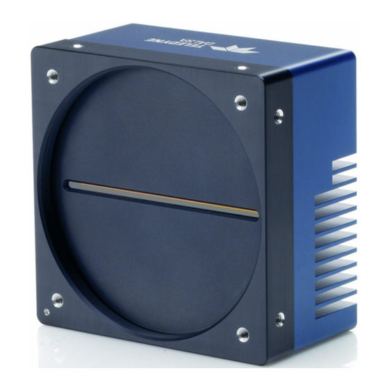
- Page 1 Piranha XL™ XDR eXtended Dynamic Range PX-HM-16K06X-00-R and PX-HM-16K12X-00-R sensors | cameras | frame grabbers | processors | software | vision solutions 03-032-20230-02 www.teledynedalsa.com...
- Page 2 All information provided in this manual is believed to be accurate and reliable. No responsibility is assumed by Teledyne DALSA for its use. Teledyne DALSA reserves the right to make changes to this information without notice. Reproduction of this manual in whole or in part, by any means, is prohibited without prior permission having been obtained from Teledyne DALSA.
-
Page 3: Table Of Contents
Contents THE PIRANHA XL XDR CAMERA ESCRIPTION AMERA IGHLIGHTS Key Features Programmability Applications UMBERS AND OFTWARE EQUIREMENTS ERFORMANCE PECIFICATIONS Certification & Compliance AMERA IXEL RRANGEMENT UPPORTED NDUSTRY TANDARDS GenICam™ Camera Link HS Camera Link HS Transmission Characteristics & QE P ESPONSIVITY LOTS ECHANICAL... - Page 4 Selecting 16,352 or 16,384 Active Pixels of Image Data* CHIEVING ASTER PEEDS OWER MAGE ESOLUTION CCEPTABLE INNING Using Area of Interest to Reduce Image Data & Enhance Performance Steps to Setup Area of Interest The Rules for Setting Areas of Interest (LUT) NCREASING YNAMIC...
- Page 5 Causes for Overheating & Power Shut Down ECLARATION OF ONFORMITY OCUMENT EVISION ISTORY The Piranha XL XDR Camera Contents • 3...
-
Page 6: The Piranha Xl Xdr Camera
Teledyne DALSA’s Piranha XL camera and XTIUM Camera Link HS frame grabber combine to offer a complete solution for the next generation of Automatic Optical Inspection systems. -
Page 7: Camera Highlights
Camera Highlights Key Features Highly responsive multiline CMOS-TDI • 16k pixel resolution • • Very low noise High dynamic LUT mode • Bi-directionality with fixed optical center • Binning • Small form factor • Low power • Robust Camera Link HS interface •... -
Page 8: Part Numbers And Software Requirements
Part Numbers and Software Requirements The camera is available in the following configurations: Table 1: Camera Models Comparison Part Number Resolution Maximum Line Rates Pixel Size PX-HM-16K06X-00-R 16352 pixels x 12 rows 60 kHz ( 8 rows) 5.0 µm x 5.0 µm 50 kHz (12 rows) PX-HM-16K12X-00-R 16352 pixels x 12 rows... - Page 9 Lens Mount M90x 1 mm Sensor to Camera Front Distance 12 mm Sensor Alignment (aligned to sides of camera) 100 µm Θ y (parallelism) ± 100 µm ± 100 µm ± 250 µm ± 0.2° Θ z Compliance Regulatory CE, FCC, and RoHS Communications Standards GenICam, Camera Link HS N ote 1: The camera w ill operate below 14 kH z w hen using an external trigger but show global and pixel based...
-
Page 10: Certification & Compliance
50 kHz line rate • • Light source: green LED 525 nm • Front plate temperature: 45º C Environmental Specifications Storage temperature range -20 °C to +80 °C Humidity (storage and operation) 15% to 85% relative, non-condensing MTBF (mean time between failures) >... -
Page 11: Genicam
The CMOS TDI sensor used in the camera is made up of a 16,384 x 12 line array of 5 µm x 5 µm pixels. Each line of pixels is spaced 5 µm apart to accommodate pixel interface circuitry. 16 pixels at each edge of the array are reserved for special use by the camera, resulting in 16,352 pixels being available to the user. -
Page 12: Camera Link Hs Transmission Characteristics
Camera Frame Grabber (C2,7M1) (C2,7M1) Command Video Link Channel Channel Data Lane 0 Data Lane 6 Figure 2. Single CLHS Connector Configuration The command channel is used by the frame grabber to send command, configuration, and programming data to the camera and to receive command responses, status, and image data from the camera. -
Page 13: Responsivity & Qe Plots
16K ROI 12K ROI 8K ROI Burst Continuous Burst Continuous Burst Continuous 8 bit 125,000 97,600 125,000 125,000 125,000 125,000 12 bit 86,000 48,800 114,000 65,000 125,000 97,000 Responsivity & QE Plots The Piranha XL XDR Camera • 11... - Page 14 12 • The Piranha XL XDR Camera...
-
Page 15: Mechanical Drawings
Mechanical Drawings The Piranha XL XDR Camera • 13... -
Page 16: Precautions
Install & Configure Frame Grabber & Software We recommend the Teledyne DALSA XTIUM frame grabber or equivalent, described in detail on the teledynedalsa.com site here. Follow the manufacturer’s installation instructions. A GenICam compliant XML device description file is embedded within the camera firmware allowing for GenICam compliant applications to recognize the camera’s capabilities immediately after... - Page 17 An important component of CamExpert is its live acquisition display window. This window allows the user to immediately verify the timing or control parameters without needing to run a separate acquisition program. To control the camera and frame grabber settings, the user must open two instances of CamExpert—one is used to control the frame grabber features and as a display window.
-
Page 18: Camexpert Panes
CamExpert Panes CamExpert, first instance: select Camera Link HS Mono using the Device drop-down menu. Figure 3. CamExpert Frame Grabber Control Window CamExpert, second instance: select PX_HM_16k12B_00_R using the Device drop-down menu. 16 • The Piranha XL XDR Camera... - Page 19 Figure 4. CamExpert Camera Control Window The CamExpert application uses panes to organize the selecting and configuring of camera files or acquisition parameters. Device Selector pane: View and select from any installed Sapera acquisition device. Once a device is selected, CamExpert will only show acquisition parameters related to that device. Optionally, select a camera file included with the Sapera installation or saved by the user.
-
Page 20: Setting Up For Imaging
Trigger button: With the I/ O control parameters set to Trigger Enabled, click to send a single trigger command. CamExpert display controls: (these do not modify the frame buffer data) Stretch image to fit, set image display to original size, or zoom the image to virtually any size and ratio. -
Page 21: Data Cables
The Camera Link HS cables are made to handle very high data rates. Cable length can be up to 15 meters. Camera Link HS cables can be bought from an OEM. OEM cables are also available for applications where flexing is present. Please see Teledyne DALSA’s website (www.teledynedalsa.com) for a list of qualified vendors and part numbers. -
Page 22: Establishing Camera Communications
sensor. Illumination beam structure can also affect edge roll off. The more diffuse the light, the less edge roll off. We recommend that the user talk to their lens provider for detailed help in selecting a suitable lens for the application and detailed lens setup design guidelines. Before starting to image, take the following steps to set up the lens to a state close to being •... -
Page 23: Establishing Data Integrity
3. Select the frame grabber device by clicking on the name Start the second instance of CamExpert. 1. CamExpert will again search for any installed Sapera devices. 2. In the Devices list area on the left side, the connected camera will be shown. 3. -
Page 24: Seamless Stop And Start Imaging
The continuous stream of encoder trigger pulses synchronized to the object motion establishes the line rate. The faster the object’s motion is, the higher the line rate. The Piranha XL camera can accommodate up to its specified maximum frequency. If the maximum frequency is exceeded, the camera will continue to output image data at the maximum specified. -
Page 25: Maximum Trigger (Line) Rate
Maximum Trigger (Line) Rate There are now two configurations of the Piranha XL camera. The high speed configuration PX-HM-16K12X-00-R has a useful operating range from 14 kHz • up to 125 kHz. It will operate below 14 kHz but may experience increased offset associated with dark current, both on a pixel and global basis. - Page 26 Figure 5. Image with proper scan direction Image scanned in direction where the TDI rows track opposite to the object motion Figure 6. Image with incorrect scan direction Some AOI systems require the scan direction to change at regular intervals, such as those scanning a panel forwards, coming to a stop, and then scanning backward as the cameras field of view is progressively indexed over the entire panel.
-
Page 27: Camera Orientation
camera field of view reaches the area to be inspected. The number of invalid lines that result after the direction change are as follows: Number of Rows Number of Invalid Lines The mechanical diagram shows which direction is designated as forward for the camera. However, due to the characteristics of the lens, the direction of the objects motion is opposite to the image motion direction. -
Page 28: Establishing The Desired Response
Establishing the Desired Response One of the most important performance characteristics of the Piranha XL camera that will determine the camera’s suitability for a specific application is its responsivity and the associated noise level at the system’s maximum line rate and under the desired illumination conditions and lens configuration. -
Page 29: Measuring Exposure Time
during evaluation is not critical and can be internal or externally triggered as long as its period does not violate the above rule. Note that when adjusting the exposure time, a momentary loss of LVAL will occur. This will also happen when changing user sets that include exposure time. -
Page 30: Image Response Uniformity
Note that when adjusting the row selection, a momentary loss of LVAL will occur. This will also happen when changing user sets that include row selection. Image Response Uniformity See the section Flat Field Category in Appendix A for GenICam features associated with this section and how to use them Relevant Features: Calibrate FPN, Calibrate PRNU, Calibration Algorithm, Calibration Target It is common to find an image with lower response at the edges of the camera’s field of view... -
Page 31: Achieving The Best Image Stability
Achieving the Best Image Stability See the section Flat Field Category in Appendix A for GenICam features associated with this section and how to use them Relevant Features: Calibrate Black Level, Auto Black Enable The camera design has been optimized to ensure that the image remains stable over a wide range of temperatures. -
Page 32: Saving & Rapid Loading A Prnu Set Only
“More >>” in CamExpert to display the full list of parameters. These features are similar to the SPR (Set PRNU Range) three letter command found in other Teledyne DALSA cameras (e.g. HS, Piranha3, and PC-30 cameras) that allow the user to set a range of PRNU values. The new feature is different in that it keeps the existing user PRNU calibration and simply scales a region up or down, thus preserving the flat field calibration. -
Page 33: Setting Custom Flat Field Coefficients
03-084-20123 Piranha XL Binary File Format which can be obtained from Teledyne DALSA Technical Support. This document also includes Excel spread sheet examples. Once the PRNU coefficients are uploaded, they are used immediately by the camera. To avoid loss at power up or changing row settings, they should be saved in one of the 8 available user sets. - Page 34 (Note: this feature is only available on the 06X and 12X models of camera.) The camera has 16,352 active pixels. 16 pixels at each end are reserved for dynamically optimizing imaging data. When it is critical for an application to have 16,384 active pixels of image data, the Image Magnification feature can be used.
-
Page 35: Using Area Of Interest To Reduce Image Data & Enhance Performance
Figure 8: 2x2 Binning For the Piranha XL camera, the default binning value is 1 x 1. Note: The Binning parameters can only be changed when image transfer to the frame grabber is stopped. Refer to the “Acquisition and Transfer Control’ category in the appendix for details on stopping and starting the acquisition. -
Page 36: The Rules For Setting Areas Of Interest
8. Start acquisition The Rules for Setting Areas of Interest Notes: The rules are dictated by how image data is organized for transmission over the available • CLHS data lanes. The camera/XML will enforce these rules truncating entered values where necessary. •... -
Page 37: Contrast
To upload a LUT, use File Access Control Category > Upload / Download File > Settings and select Look Up Table to upload a file. The file format is described in 03-084-20123 Piranha XL Binary File Format which can be obtained from Teledyne DALSA Technical Support. This document also includes Excel spread sheet examples. -
Page 38: Alignment
Help with Lens Focusing & Camera Alignment See the section Camera Control Category in Appendix A for GenICam features associated with this section and how to use them Before evaluating the cameras imaging performance, it is important to ensure that the image is properly focused and that the camera’s 16k pixel axis is perpendicular to the motion of the object. - Page 39 black-to-white single, sharp transition perpendicular to the direction of motion, and is in focus. The black to white transition should be located at the point where all the cameras are to be optically aligned. Move Edge into Field of View of Camera Then Leave Target Stationary Black to White Transition Perpendicular to Motion...
- Page 40 close and then move to 8 rows. Ensure that the 8 rows is also Flat Fielded to the same target as 12 rows. Line Profile of White/Illuminated Area Pixel # 16352 Flat Field to a Target of 200DN Pixel # 16352 Adjust Camera in Scan Direction Towards Black/ White Transition Until Line Center is 100DN...
-
Page 41: Changing Output Configuration
Changing Output Configuration Bit Resolution See the section Image Format Control Category in Appendix A for GenICam features associated with this section and how to use them Relevant Features: Pixel Format The camera can output video data as 8-bit or 12-bit format. 8-bit output allows for the maximum specified line rate to be achieved. -
Page 42: Using Fiber Modules
Using Fiber Modules The Piranha XL camera is capable of supporting one or two “CX4 Active Optical” fiber modules, which can have cable lengths up to 300 meters. The fiber module plugs directly into the camera connectors, which provide both communication and power to the module. CX4 fiber modules support four receiver lines, which results in only four image data lanes with one also carrying command response data and being available from the camera to the frame grabber. -
Page 43: Active Settings For Current Operation
GenIcam Input By GenIcam Command By GenIcam Command 1. Select a ‘Factory Set’ 1. Select a ‘User Set’ 2. Initiate a ‘User Set Load’ 2. Initiate a ‘User Set Load’ Power Up Power Up Facrory Setting Active Setting User Setting Or Reset Or Reset By GenIcam GenIcam Command... -
Page 44: Default Setting
Default Setting Either the factory or one of the user settings can be used as the default setting, by selecting the set to use in the user set default selector. The chosen set automatically becomes the default setting and is the set loaded when the camera is reset or powered up. 42 •... -
Page 45: Appendix A: Genicam Commands
Features listed in the description table but tagged as Invisible are typically reserved for Teledyne DALSA Support or third party software usage, and not typically required by end user applications. The following feature tables describe these parameters along with their view attributes and in which version of the device the feature was introduced. -
Page 46: Camera Information Category
Camera Information Category Camera information can be retrieved via a controlling application. Parameters such as camera model, firmware version, etc. are read to uniquely identify the connected Piranha XL camera. These features are typically read-only. The Camera Information Category groups information specific to the individual camera. In this category the number of features shown is identical whether the view is Beginner, Expert, or Guru. - Page 47 Display Name Feature Description Device Version & View Firmware Version DeviceFirmwareVersion Displays the currently loaded firmware version 1.00 number. Firmware files have a unique number Beginner and have the .cbf file extension. (RO) Serial Number DeviceID Displays the device’s factory set camera serial 1.00 number.
- Page 48 Display Name Feature Description Device Version & View UserSet5 UserSet5 Select the User-defined Configuration space UserSet5 to save to or load from features settings previously saved by the user. UserSet6 UserSet6 Select the User-defined Configuration space UserSet6 to save to or load from features settings previously saved by the user.
-
Page 49: Built-In Self-Test Codes (Bist)
Built-In Self-Test Codes (BIST) In the Camera Information screen shot example above, the Power-On Status is showing the 23 status flags where ‘1’ is signaling an issue. When there are no issues, the Power-On status will indicated “Good”. Details of the BIST codes can be found in the Trouble Shooting Guide in Appendix B. Camera Power-Up Configuration Selection Dialog CamExpert provides a dialog box which combines the menu option used to select the camera’s power-up state and the options for the user to save or load a camera state as a specific user set... -
Page 50: Camera Control Feature Descriptions
Figure 13: Camera Control Panel Camera Control Feature Descriptions Display Name Feature Description Device Version & View Device Scan DeviceScanType Used to set the camera scanning mode. Only 1.00 Type standard TDI mode is available. Beginner SNFC Standard Internal Line AcquisitionLineRate Specifies the camera internal line rate, in Hz when 1.00... -
Page 51: Digital I / O Control Feature Descriptions
Display Name Feature Description Device Version & View Measured measureExposureTime Specifies the exposure time provided to the camera 1.00 Exposure Time by either internal or external source (RO) Beginner Refreshed refreshMeasureExposureTime Press to display the current exposure time provided 1.00 measured to the camera. -
Page 52: Flat Field Category
Figure 14 Digital I/O Control Panel Display Name Feature Description Device Version & View Trigger Mode Trigger Mode Determines the source of trigger to the camera, 1.00 internal or external DFNC Beginn Flat Field Category The Piranha XL Flat Field controls, as shown by CamExpert, group parameters used to control the FPN and PRNU calibration process. -
Page 53: Flat Field Control Feature Description
Figure 15: Flat Field Panel Flat Field Control Feature Description Display Name Feature Description Device Version & View Mode flatfieldCorrectionMode 1.00 FPN and flat field coefficients Beginner disabled. FPN and flat field coefficients DFNC enabled. Clear Coefficents Initialize Reset all FPN to 0 and all flat field coefficients to 1. - Page 54 Display Name Feature Description Device Version & View DFNC Peak Peak Calculation of PRNU coefficients to bring all pixels to the peak. Peak, Image Filtered Peak, Image Filtered A low pass filter is applied to the average line values before calculating the coefficients.
- Page 55 Display Name Feature Description Device Version & View User PRNU Set selector flatfieldCorrectionCurrentActiveSet Selects the User PRNU set to be 1.00 saved or loaded. Guru DFNC Factory set can only be loaded. Factory Set Factory Set Only the PRNU values are saved User set (1 thru 8) User set (1 thru 8) or loaded which is much faster...
-
Page 56: Image Format Control Category
Display Name Feature Description Device Version & View Image Magnification Mode imageMagnificationMode When active, the image is 1.00 magnified by 1.002x allowing the Beginner 16 black pixels at each end to be DFNC replaced with image data resulting in a16,384 pixel wide image. Turns Image Magnification off. - Page 57 Test Pattern TestImageSelector Selects the type of test image that is sent by 1.00 the camera. Choices are either as defined by Beginner SNFC and/or as provided by the device DFNC manufacturer. Selects sensor video to be output from sensor Each Tap Fixed Each Tap Fixed Selects a grey scale for each tap of the...
-
Page 58: Transport Layer Control Category
Transport Layer Control Category Note: All features shown in Guru visibility. Figure 17: Transport Layer Panel Transport Layer Feature Descriptions Display Name Feature Description Device Version & View XML Major Version DeviceManifestXMLMajorVersion Together with 1.00 DeviceManifestXMLMinorVersion Beginner DFNC specifies the GenICam™ feature description XML file version (RO) XML Minor Version... - Page 59 CLHS Discovery clhsDiscovery Selects between CLHS discovery mode 1.00 which automatically determines the Guru configuration of the CLHS interface DFNC when enabled. When disabled, the frame grabber needs to have the configuration set by the user CLHS transmitters are enabled immediately on power up CLHS transmitters enable after sending Discovery Disabled...
-
Page 60: Acquisition And Transfer Control Category
Acquisition and Transfer Control Category Figure 18: Acquisition & Transfer Control Panel Acquisition and Transfer Control Feature Descriptions Display Name Feature Description Device Version & View Acquisition Mode AquisitionMode The device acquisition mode defines the number of frames to 1.00 capture during an acquisition and the way it stops Beginner DFNC... -
Page 61: File Access Control Feature Descriptions
Figure 19: File Access Control Panel File Access Control Feature Descriptions Display Name Feature Description View File Selector FileSelector Selects the file to access. The file types which are accessible 1.00 are device-dependent. Beginner All Firmware Upload micro code, FPGA code &XML as a single file to the DFNC camera which will execute on the next camera reboot cycle. - Page 62 Display Name Feature Description View File Access FileAccessBuffer Defines the intermediate access buffer that allows the exchange 1.00 Buffer of data between the device file storage and the application. Guru File Access FileAccessOffset Controls the mapping offset between the device file storage and 1.00 Offset the file access buffer.
-
Page 63: File Access Via The Camexpert Tool
3. In the “Type” drop down box select “Miscellaneous.” 4. In the “File selector” drop down box select “CameraData.” 5. Hit “Download” 6. Save the text file and send the file to Teledyne DALSA customer support. The Piranha XL XDR Camera • 61... -
Page 64: Appendix B: Trouble Shooting Guide
This text file can be downloaded from the camera and forwarded to Teledyne DALSA Technical Customer support team to aid in diagnosis of any reported issues. See Saving & Restoring Camera Setup Configurations of the Piranha XL User Manual for details on downloading the Camera Data file. -
Page 65: Status Led
SUCCESS 0x00000000 No errors detected I2C Error 0x00000001 Camera internal hardware FPGA_NO_INIT 0x00000002 Camera internal hardware FPGA_NO_DONE 0x00000004 Camera internal hardware EXT_SRAM ERROR 0x00000008 Camera internal hardware ECHO_BACK ERROR 0x00000010 Camera internal hardware FLASH_TIMEOUT 0x00000020 Camera internal hardware FLASH_ERROR 0x00000040 Camera internal hardware NO_FPGA_CODE 0x00000080... -
Page 66: Resolving Camera Issues
been broken. Constant Green The CLHS Link has been established and data transfer may begin Resolving Camera Issues Communications No Camera Features when Starting CamExpert If the camera’s CamExpert GUI is opened and no features are listed, then the camera may be experiencing lane lock issues. -
Page 67: Image Quality Issues
Image Quality Issues Vertical Lines Appear in Image after Calibration The purpose of flat field calibration is to compensate for the lens edge roll-off and imperfections in the illumination profiles by creating a uniform response. When performing a flat field calibration, the camera must be imaging a flat white target that is illuminated by the actual lighting used in the application. - Page 68 an external synchronization (EXSYNC) signal to the camera, where one pulse is generated when the object moves by the size of one object pixel. See ‘External Trigger Mode’ in the user manual. Any transport motion that is not correctly reflected in the EXSYNC pulses will cause image distortion in the scan direction.
- Page 69 Below is an example of the precautions necessary to achieve a smooth start to imaging from a stopped condition using a non-ideal transport mechanism. The test bench transport mechanism discussed here has an encoder which is an integrated part of the servo drive motor.
- Page 70 The following sections detail the causes of possible image quality problems with respect to optical misalignment and how to identify them. Image Will Not Focus Well over the Entire FOV If the image is skewed with respect to the sensor pixel array, then a sharp image perpendicular to object travel will not be achievable regardless of attempts to adjust focus.
- Page 71 No sideways component as Digital image will image moves appear smeared in across the long axis of the sensor Higher pixels array Magnification Pixels Pixels Camera Angle Lower Causes Parallax Magnification Image has sideways component as it moves across the pixels array Camera Not Perpendicular to Object Surface Shorter Optical...
- Page 72 Worse Worse Worse Worse Focus Focus Focus Focus Good Good Good Focus Focus Focus Figure 23 Effects of Camera Tilt In the Long Sensor Axis A mechanical means to adjust this angle may need to be incorporated into the camera mount. This becomes a finer, more precise adjustment as the magnification increases, especially above 1x, as the depth of field becomes progressively smaller.
-
Page 73: Power Supply Issues
Power Supply Issues For reliable operation the camera input supply must be within +12 V to +24 V. The power supply to the camera should be suitably current limited as per the applied input voltage of between +12 V to +24 V. Assume a worst case power consumption of 24 W and a 150% current rating for the breaker or fuse. - Page 74 Declaration of Conformity 72 • The Piranha XL XDR Camera...
- Page 75 Document Revision History Revision Description Date • Initial release of the XDR version of the manual. February 19, 2016 For the user manual describing the high gain camera model— PX- • HM-16K12B-00-R—see document 03-032-20216. Backwards compatible software upgrade implemented. SFR ROI, October 31, 2016 •...
Need help?
Do you have a question about the Piranha XL XDR PX-HM-16K06X-00-R and is the answer not in the manual?
Questions and answers