
Subscribe to Our Youtube Channel
Related Manuals for Dalsa Piranha XL PX-HM-16K12B-00-R


Summary of Contents for Dalsa Piranha XL PX-HM-16K12B-00-R
- Page 1 Piranha XL™ Camera User’s Manual PX-HM-16K12B-00-R and PX-HM-16K06B-00-R sensors | cameras | frame grabbers | processors | software | vision solutions 03-032-20216-03 www.teledynedalsa.com...
- Page 2 All information provided in this manual is believed to be accurate and reliable. No responsibility is assumed by Teledyne DALSA for its use. Teledyne DALSA reserves the right to make changes to this information without notice. Reproduction of this manual in whole or in part, by any means, is prohibited without prior permission having been obtained from Teledyne DALSA.
-
Page 3: Table Of Contents
Contents THE PIRANHA XL CAMERA IGHLIGHTS Key Features Programmability Applications Model Performance Specifications Piranha XL’s Physical Pixel Arrangement & C ERTIFICATION OMPLIANCE UPPORTED NDUSTRY TANDARDS GenICam™ Camera Link HS Camera Link HS Transmission Characteristics & QE P ESPONSIVITY LOTS ECHANICAL RAWINGS RECAUTIONS Electrostatic Discharge and the CMOS Sensor... - Page 4 The Rules for Setting Areas of Interest NCREASING YNAMIC ANGE ONTRAST NHANCEMENT & C ELP WITH OCUSING AMERA LIGNMENT Establish Optimum focus Ensuring Rows are Aligned to the Object Motion HANGING UTPUT ONFIGURATION Bit Resolution Camera Link HS Lane Selection Using Two CLHS Cables Using Fiber Modules &...
- Page 5 Randomly Compressed Images Distorted Image when Stopping and Starting Distorted Image when Changing Direction Optical Misalignment Issues Image Will Not Focus Well over the Entire FOV Image Will Not Focus at Edges of Field of View. Image Will Focus Well on One Side but Not the Other at the Same Time Power Supply Issues Causes for Overheating &...
-
Page 6: The Piranha Xl Camera
Teledyne DALSA’s Piranha XL camera and XTIUM Camera Link HS frame grabber combine to offer a complete solution for the next generation of Automatic Optical Inspection systems. -
Page 7: Applications
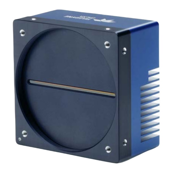
Applications Flat-panel LCD and OLED display inspection • Web inspection • Printed circuit board inspection • High throughput and high resolution applications • Model The camera is available in the following configurations: Table 1: Camera Models Comparison Piranha XL Multi Line Model Comparison Part Number Resolution Maximum Line Rates... - Page 8 Typical Power Dissipation 23 W Size 97 mm (W) x 97 mm (H) x 61 mm (D) Mass 685 grams Operating Temp +0 °C to +60°C, front plate temperature Optical Interface Lens Mount M90x 1 mm Sensor to Camera Front Distance 12 mm Sensor Alignment (aligned to sides of camera) Θ...
-
Page 9: Piranha Xl's Physical Pixel Arrangement
Piranha XL’s Physical Pixel Arrangement Single 5um Gap Single 5um x 5um Between Each Active Pixels Size 16,352 Active Pixel Columns Row of Pixels CMOS TDI Mode Optical Center High 16,384 x 12 Rows Does Not Move Sensitivity Pixel Array with Direction 12 Rows Change... -
Page 10: Certification & Compliance
Certification & Compliance Compliance EN 55011, FCC Part 15, CISPR 11, and ICES-003 Class A Radiated Emissions Requirements EN 55024 and EN 61326-1 Immunity to Disturbance RoHS per EU Directive 2011/65/EC and WEEE per EU Directive 2002/96/EC and China Electronic Industry Standard SJ/T11364-2006 Supported Industry Standards GenICam™... -
Page 11: Camera Link Hs Transmission Characteristics
The command channel is used by the frame grabber to send command, configuration, and programming data to the camera and to receive command responses, status, and image data from the camera. The designation C2,7M1 defines the use of a SFF-8470 connector (C2) and up to 7 lanes of data with 1 command channel using M-Protocol (8b/10b) at the default speed of 3.125Gb/sec. -
Page 12: Responsivity & Qe Plots
Responsivity & QE Plots 10 • The Piranha XL Camera... -
Page 13: Mechanical Drawings
Mechanical Drawings • 11 The Piranha XL Camera... -
Page 14: Precautions
Install & Configure Frame Grabber & Software We recommend the Teledyne DALSA XTIUM frame grabber or equivalent, described in detail on the teledynedalsa.com site here. Follow the manufacturer’s installation instructions. A GenICam compliant XML device description file is embedded within the camera firmware allowing for GenICam compliant applications to recognize the camera’s capabilities immediately after... - Page 15 An important component of CamExpert is its live acquisition display window. This window allows the user to immediately verify the timing or control parameters without needing to run a separate acquisition program. To control the camera and frame grabber settings, the user must open two instances of CamExpert—one is used to control the frame grabber features and as a display window.
-
Page 16: Camexpert Panes
CamExpert Panes CamExpert, first instance: select Camera Link HS Mono using the Device drop-down menu. Figure 3. CamExpert Frame Grabber Control Window CamExpert, second instance: select PX_HM_16k12A_00_R using the Device drop-down menu. 14 • The Piranha XL Camera... - Page 17 Figure 4. CamExpert Camera Control Window The CamExpert application uses panes to organize the selecting and configuring of camera files or acquisition parameters. Device Selector pane: View and select from any installed Sapera acquisition device. Once a device is selected, CamExpert will only show acquisition parameters related to that device. Optionally, select a camera file included with the Sapera installation or saved by the user.
-
Page 18: Setting Up For Imaging
Trigger button: With the I/O control parameters set to Trigger Enabled, click to send a single trigger command. CamExpert display controls: (these do not modify the frame buffer data) Stretch image to fit, set image display to original size, or zoom the image to virtually any size and ratio. -
Page 19: Data Cables
The Camera Link HS cables are made to handle very high data rates. Cable length can be up to 15 meters. Camera Link HS cables can be bought from an OEM. OEM cables are also available for applications where flexing is present. Please see Teledyne DALSA’s website (www.teledynedalsa.com) for a list of qualified vendors and part numbers. -
Page 20: Establishing Camera Communications
• Before starting to image, take the following steps to set up the lens to a state close to being focused: In the lens specification, find the distance from the lens mounting flange surface to its • principle plane. Determine the magnification for your application = sensor pixel size (5 µm) / object pixel •... -
Page 21: Establishing Data Integrity
Start the second instance of CamExpert. 1. CamExpert will again search for any installed Sapera devices. 2. In the Devices list area on the left side, the connected camera will be shown. 3. Select the camera device by clicking on the name. 4. -
Page 22: Internal Trigger Mode
camera will continue to output image data at the maximum specified. The result will be that some trigger pulses will be missed and there will be an associated distortion of the image data. When the line rate returns to below the maximum specified, then normal imaging will be reestablished. The Piranha XL camera can accommodate the full range of line rate frequency—from the maximum specified to a stopped condition. -
Page 23: Maximum Trigger (Line) Rate
Maximum Trigger (Line) Rate There are now two configurations of the Piranha XL camera. The high speed configuration PX-HM-16K12B-00-R has a useful operating range from 14 kHz • up to 125 kHz. It will operate below 14 kHz but may experience increased offset associated with dark current, both on a pixel and global basis. - Page 24 Relevant Features: Direction Source, Internal Direction The Piranha XL camera can accommodate a forward and reverse scan direction. The sensor timing must follow the image as it moves over its imaging area. If the direction is wrong then the image will look out of focus, as can be seen in the following figure.
-
Page 25: Camera Orientation
progressively indexed over the entire panel. Direction can be dynamically controlled by sending the appropriate direction command to the camera or via the CLHS GPIO (General Purpose Input / Output) control bits. The CLHS GPIO direction is controlled by writing Frame Grabber register #80524, bit 2. -
Page 26: Establishing The Desired Response
Establishing the Desired Response One of the most important performance characteristics of the Piranha XL camera that will determine the camera’s suitability for a specific application is its responsivity and the associated noise level at the system’s maximum line rate and under the desired illumination conditions and lens configuration. -
Page 27: Measuring Exposure Time
When evaluating the responsivity of the camera, set the exposure time to the maximum allowable for the system, minus any margin required for illumination degradation, if applicable. The line rate during evaluation is not critical and can be internal or externally triggered as long as its period does not violate the above rule. -
Page 28: Image Response Uniformity
Note that when adjusting the row selection, a momentary loss of LVAL will occur. This will also happen when changing user sets that include row selection. Image Response Uniformity See the section Flat Field Category in Appendix A for GenICam features associated with this section and how to use them Relevant Features: Calibrate FPN, Calibrate PRNU, Calibration Algorithm, Calibration Target It is common to experience a lower response image at the edges of the camera’s field of view... -
Page 29: Setting Custom Prnu Coefficients
03-084-20123 Piranha XL Binary File Format which can be obtained from Teledyne DALSA Technical Support. This document also includes Excel spread sheet examples. Once the PRNU coefficients are uploaded, they are used immediately by the camera. To avoid loss at power up or changing row settings, they should be saved in one of the 8 available user sets. -
Page 30: Achieving Faster Scan Speeds When Lower Image Resolution Is Acceptable (Binning)
Achieving Faster Scan Speeds When Lower Image Resolution Is Acceptable (Binning) See the section Image Format Control Category in Appendix A for GenICam features associated with this section and how to use them Relevant Features: Horizontal Binning, Vertical Binning In certain applications, lower image resolution may be acceptable if the desired defect detection can still be achieved. -
Page 31: Steps To Setup Area Of Interest
Different Areas of Interest can also be selected to be output on the Master and Salve ports. This would allow the camera to be connected to a dual port frame grabber or two frame grabbers, possibly in two PC’s. Using this configuration may eliminate frame grabber and/or PC bandwidth issues allowing the camera to achieve its maximum line rate. -
Page 32: Ontrast Enhancement
To upload a LUT, use File Access Control Category > Upload / Download File > Settings and select Look Up Table to upload a file. The file format is described in 03-084-20123 Piranha XL Binary File Format which can be obtained from Teledyne DALSA Technical Support. This document also includes Excel spread sheet examples. -
Page 33: Help With Lens Focusing & Camera Alignment
Note: A positive offset value is not useful for contrast enhancement. However, it can be used while measuring the dark noise level of the camera to ensure zero clipping is not present. Help with Lens Focusing & Camera Alignment See the section Camera Control Category in Appendix A for GenICam features associated with this section and how to use them Before evaluating the cameras imaging performance, it is important to ensure that the image is properly focused and that the camera’s 16k pixel axis is perpendicular to the motion of the object. -
Page 34: Ensuring Rows Are Aligned To The Object Motion
Ensuring Rows are Aligned to the Object Motion To achieve the best image quality, it is important that the object motion tracks across the CMOS TDI rows without any up or down movement. One method of achieving this is to align the CMOS TDI rows to the object motion by using a stationary target located at the object plane, which has a black-to-white single, sharp transition perpendicular to the direction of motion, and is in focus. - Page 35 When both end of the line profile are equal to the center, then the camera will be aligned • both in the scan direction and rotationally with the black-to-white transition. The accuracy of the adjustment can be increased by using 8 rows or even 4 rows. However, •...
-
Page 36: Changing Output Configuration
This method is not effective for CCD TDI cameras with many stages as there is insufficient sensitivity. Area mode imaging is required. Single line cameras would be too sensitive. However, the Piranha XL camera has the right number of rows to make this simple alignment method practical. -
Page 37: Using Fiber Modules
Using Fiber Modules The Piranha XL camera is capable of supporting one or two “CX4 Active Optical” fiber modules, which can have cable lengths up to 300 meters. The fiber module plugs directly into the camera connectors, which provide both communication and power to the module. CX4 fiber modules support four receiver lines, which results in only four image data lanes with one also carrying command response data and being available from the camera to the frame grabber. -
Page 38: Active Settings For Current Operation
GenIcam Input By GenIcam Command By GenIcam Command 1. Select a ‘Factory Set’ 1. Select a ‘User Set’ 2. Initiate a ‘User Set Load’ 2. Initiate a ‘User Set Load’ Power Up Power Up Facrory Setting Active Setting User Setting Or Reset Or Reset By GenIcam GenIcam Command... -
Page 39: Default Setting
Features listed in the description table but tagged as Invisible are typically reserved for Teledyne DALSA Support or third party software usage, and not typically required by end user applications. The following feature tables describe these parameters along with their view attributes and in which version of the device the feature was introduced. -
Page 40: Camera Information Category
Camera Information Category Camera information can be retrieved via a controlling application. Parameters such as camera model, firmware version, etc. are read to uniquely identify the connected Piranha XL camera. These features are typically read-only. The Camera Information Category groups information specific to the individual camera. In this category the number of features shown is identical whether the view is Beginner, Expert, or Guru. -
Page 41: Camera Information Feature Descriptions
Camera Information Feature Descriptions Display Name Feature Description Device Version & View Model Name DeviceModelName Displays the device model name. (RO) 1.00 Beginner Vendor Name DeviceVendorName Displays the device vendor name. (RO) 1.00 Beginner Device Version DeviceVersion Displays the device version. This tag will also 1.00 highlight if the firmware is a beta or custom Beginner... - Page 42 Display Name Feature Description Device Version & View UserSet 1 UserSet1 Select the User-defined Configuration space UserSet1 to save to or load from features settings previously saved by the user. UserSet 2 UserSet2 Select the User-defined Configuration space UserSet2 to save to or load from features settings previously saved by the user.
-
Page 43: Built In Self Test Codes
Display Name Feature Description Device Version & View Refresh Temperature refreshTemperature Press to display the current internal operating 1.00 temperature of the camera. DFNC Beginner Input Voltage deviceInputVoltage Displays the input voltage to the camera at the 1.00 power connector (RO) DFNC Beginner Refresh Voltage... -
Page 44: User Set Configuration Management
User Set Configuration Management The second drop list allows the user to change the camera configuration anytime after a power-up (see feature UserSetSelector). To reset the camera to the factory configuration, select Factory Setting and click Load. To save a current camera configuration, select User Set 1 to 8 and click Save. -
Page 45: Camera Control Feature Descriptions
Camera Control Feature Descriptions Display Name Feature Description Device Version & View Device Scan DeviceScanType Used to set the camera scanning mode. Only 1.00 Type standard TDI mode is available. Beginner SNFC Standard Internal Line AcquisitionLineRate Specifies the camera internal line rate, in Hz when 1.00 Rate Trigger mode set to internal. -
Page 46: Digital I / O Control Feature Descriptions
Display Name Feature Description Device Version & View Offset BlackLevel Controls the black level as an absolute physical 1.00 value. This represents a DC offset applied to the Beginner video signal, in DN (digital number) units. Digital I / O Control Feature Descriptions The camera’s Digital I / O Control category is used to determine the source of the line sync generator. -
Page 47: Flat Field Category
Flat Field Category The Piranha XL Flat Field controls, as shown by CamExpert, group parameters used to control the FPN and PRNU calibration process. Figure 15: Flat Field Panel Flat Field Control Feature Description Display Name Feature Description Device Version &... - Page 48 Display Name Feature Description Device Version & View LowPass LowPass A low pass filter is first applied to the average line values before calculating the coefficients. Use this algorithm if the calibration target is not uniformly white or it is not possible to defocus the image.
-
Page 49: Image Format Control Category
Image Format Control Category The Piranha XL Image Format controls, as shown by CamExpert, groups parameters used to configure camera pixel format, image cropping, binning and test pattern generation features. Figure 16: Image Format Panel • 47 The Piranha XL Camera... -
Page 50: Image Format Control Feature Description
Image Format Control Feature Description Display Name Feature Description Device Version & View Test Pattern TestImageSelector Selects the type of test image that is sent by 1.00 the camera. Choices are either as defined by Beginner SNFC and/or as provided by the device DFNC manufacturer. -
Page 51: Transport Layer Control Category
10 Bits/Pixel Bpp10 Senor input data path is 8, 12 or 16 bits per 12 Bits/Pixel Bpp12 pixel. 16 Bits/Pixel Bpp 16 Transport Layer Control Category Note: All features shown in Guru visibility. Figure 17: Transport Layer Panel • 49 The Piranha XL Camera... -
Page 52: Transport Layer Feature Descriptions
Transport Layer Feature Descriptions Display Name Feature Description Device Version & View XML Major Version DeviceManifestXMLMajorVersion Together with 1.00 DeviceManifestXMLMinorVersion Beginner DFNC specifies the GenICam™ feature description XML file version (RO) XML Minor Version DeviceManifestXMLMinorVersion Together with 1.00 DeviceManifestXMLMajorVersion Beginner DFNC specifies the GenICam™... -
Page 53: Acquisition And Transfer Control Category
CLHS 8b/10b clhsErrorCountSelector Selects the error count that the 1.00 Receive Error Count following three features apply to Guru selector DFNC Data 2 Receive Error Count Control/Data1 Receive Error Count CLHS 8b/10b clhsError Count CLHS error count value for the selected 1.00 Receive Error Count data/control lanes (RO) -
Page 54: File Access Control Category
Acquisition Stop AquisitionStop Stops the acquisition of image data at the end of the next 1.00 frame(s) sequence (WO) Beginner DFNC Acquisition Status AquisitionStatus Indicates whether the camera has been commanded to stop 1.00 or to send image data. Beginner DFNC File Access Control Category The File Access control in CamExpert allows the user to quickly upload and download of various... - Page 55 Display Name Feature Description View CameraData Download camera information and send for customer support. File Operation Selector FileOperationSe Selects the target operation for the selected file in the device. 1.00 lector This operation is executed when the File Operation Execute Guru feature is called.
-
Page 56: File Access Via The Camexpert Tool
3. In the “Type” drop down box select “Miscellaneous.” 4. In the “File selector” drop down box select “CameraData.” 5. Hit “Download” 6. Save the text file and send the file to Teledyne DALSA customer support. 54 • The Piranha XL Camera... -
Page 57: Appendix B: Trouble Shooting Guide
This text file can be downloaded from the camera and forwarded to Teledyne DALSA Technical Customer support team to aid in diagnosis of any reported issues. See Saving & Restoring Camera Setup Configurations of the Piranha XL User Manual for details on downloading the Camera Data file. -
Page 58: Status Led
What each flag signifies: BIST Error Description Status Code (Bit Set) Potential Cause SUCCESS 0x00000000 No errors detected I2C Error 0x00000001 Camera internal hardware FPGA_NO_INIT 0x00000002 Camera internal hardware FPGA_NO_DONE 0x00000004 Camera internal hardware EXT_SRAM ERROR 0x00000008 Camera internal hardware ECHO_BACK ERROR 0x00000010 Camera internal hardware... -
Page 59: Resolving Camera Issues
Resolving Camera Issues Communications No Camera Features when Starting CamExpert If the camera’s CamExpert GUI is opened and no features are listed, then the camera may be experiencing lane lock issues. While using the frame grabber CamExpert GUI you should be able to see a row of status indicators below the image area that indicates the status of the CLHS communications. -
Page 60: Over Time, Some Pixels Develop Low Response
imperfections will appear as vertical stripes in the image. If the white reference had imperfections that caused dark features, there will be a bright vertical line during normal imaging. Similarly, bright features will cause dark lines. It can be very difficult to achieve a perfectly uniform, defect- free white reference. -
Page 61: Continuously Smeared, Compressed Or Stretched Images
Continuously Smeared, Compressed or Stretched Images When accurate synchronization is not achieved, the image will appear smeared in the scan direction. If the EXSYNC pulses are coming too fast, then the image will appear smeared and stretched in the machine direction. If the pulses are too slow, then the image will appear smeared and compressed. -
Page 62: Distorted Image When Changing Direction
1. Before imaging was triggered, the transport was moved forward a few millimetres at a very slow speed and stopped to take up the slack. 2. The transport was then stopped for a sufficient time for the vibrations to die out. 3. -
Page 63: Image Will Not Focus At Edges Of Field Of View
TDI pixel array skewed with respect to image Image TDI Pixel Summing Image feature has sideways component Image Motion as it moves across the pixels array Digital image will appear smeared in long axis of the sensor Figure 21 Effects of Camera Skew The camera mounting assembly should have a mechanism to minimize any skew between the image motion and TDI summing direction. -
Page 64: Image Will Focus Well On One Side But Not The Other At The Same Time
Note: If you have confirmed that the camera’s optical axis is perpendicular to the material surface and you still have difficulty focusing at the edges, then check that the lens specification for MTF characteristics over the entire field of view. The MTF of lenses typically reduces at the edges of the field of view. -
Page 65: Power Supply Issues
Power Supply Issues For reliable operation the camera input supply must be within +12 V to + 24 V. The power supply to the camera should be suitably current limited as per the applied input voltage of between +12 V to +24 V. Assume a worst case power consumption of 24 W and a 150% current rating for the breaker or fuse. -
Page 66: Declaration Of Conformity
Declaration Of Conformity 64 • The Piranha XL Camera...
Need help?
Do you have a question about the Piranha XL PX-HM-16K12B-00-R and is the answer not in the manual?
Questions and answers