
Subscribe to Our Youtube Channel
Related Manuals for Response SL3


Summary of Contents for Response SL3
- Page 1 6 Zone Wireless Security Alarm SL3 / SL8 ZONE 1 ZONE 2 ZONE 3 ZONE 4 ZONE 5 ZONE 6 FIRE TAMPER POWER PART ARM LOW BATT. ENTER Installation & Operating Manual...
- Page 2 FOREWORD DEVICE RANGE All devices in this wireless Alarm System are designed and manufactured to provide long reliable The quoted range of the system devices (see component service. The system is designed for ease of specification on rear cover) is measured in ideal installation using only conventional domestic tools.
-
Page 3: Table Of Contents
CONTENTS Power-up of the Solar Siren KIT CONTENTS Linking the Solar Siren to the Control Panel INTRODUCTION AND OVERVIEW Testing the Wireless Solar Siren System Arming Mounting the Solar Siren on to the wall Entry/Exit Delay SPECTRA LIGHTING RECEIVER Zones Linking the Control Panel to the Spectra Zone Lockout Lighting Receiver... -
Page 4: Kit Contents
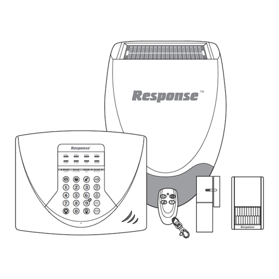
KIT CONTENTS The Alarm System should contain the following devices. Solar Siren Control Panel Remote Control PIR Movement Detectors Door / Window Detectors Also included: Siren Mounting Template Installation & Operating Manual Fixing pack Batteries Please Note: Solar Siren An installation video is available on-line at www.friedlandproducts.com ZONE 1 ZONE 2... -
Page 5: Introduction And Overview
INTRODUCTION AND OVERVIEW SYSTEM ARMING until after the Entry/Exit period has ended. If the system is not disarmed during the delay period, The system has a ‘Full Arm’ and a ‘Part-Arm’ facility. the alarm will sound when the delay period expires. Full Arm will arm all zones while the ‘Part-Arm’... -
Page 6: Jamming Detection
the alarm even if the system is Disarmed (unless the your choice that only you and other authorised system is in Test or Program modes). system users know. JAMMING DETECTION PLANNING AND EXTENDING In order to detect any attempts to illegally jam the YOUR ALARM SYSTEM radio channel used by your alarm system, a special jamming detection function is incorporated into the... - Page 7 ZONE 1 ZONE 2 ZONE 3 ZONE 4 ZONE 5 ZONE 6 FIRE TAMPER POWER PART ARM LOW BATT. ENTER Control Panel Remote Control SHED PIR Movement Detector Back Door KITCHEN DINING ROOM Magnetic Door/Window HALL Detector LOUNGE GROUND FLOOR GARAGE External Solar Siren...
-
Page 8: Remote Control Unit
REMOTE CONTROL UNIT The Remote Control Unit(s) is used to Arm in either Arm or Part Arm modes and to Disarm the system. Transmit LED Instant-Arm Insert a small coin into the slot on the edge of the housing to gently lever open Disarm Delay-Arm Battery... -
Page 9: Installing The Control Panel
mounted. The Control Panel should be mounted INSTALLING THE CONTROL PANEL at a convenient height of between 1.5 and Undo the two cover fixing screws on top of the 2 metres and in a position where it will be panel and open the cover. The cover is hinged seen each day. -
Page 10: Learning A New Remote Control / Keypad
Control Panel over these screws using the two Note: The Power LED may flash to indicate that keyhole slots in the top corners of the panel the unit is being operated from the back-up casing. batteries and that mains supply is not present. Close the lid of the Control Panel and fasten the Route the cable from the Power Supply Adaptor cover fixing screws. -
Page 11: Testing The Control Panel And Remote Control
Press the button on the new Remote To delete all linked Remote Controls/Keypads Control or from the Control Panel: Press Place the Control Unit into Learn Mode. With Keypad User Access Code the system in Standby on the Remote Keypad. Press ENTER User Access Code... -
Page 12: Passive Infra-Red (Pir) Movement Detectors
Activate the Personal Attack switch on the The PIR Detector is powered by a 9V PP3 Alkaline Remote Control. battery which under normal conditions will have an expected life of approximately 1 year. When the The Control Panel alarm will sound and all battery level drops, with the PIR in normal operation Zone/Fire/Tamper LEDs will flash. -
Page 13: Installing And Configuring The Pir Detectors
Where possible, mount the Detector in the Carefully drill out the required mounting holes in corner of the room so that the logical path of an the rear cover using a 3mm drill according to intruder would cut across the fan detection whether the unit is being mounted in a corner or pattern. -
Page 14: Testing The Pir Detectors
Connect the PP3 Alkaline battery to the battery in order to conserve power and maximise clip. The LED behind the lens will rapidly flash battery life the PIR Detector will only detect for approximately 2-3 minutes until the PIR has movement if there has been no movement stabilised. -
Page 15: Positioning The Door / Window Detectors
POSITIONING THE DOOR / WINDOW Slide the two batteries supplied into the battery DETECTORS holder, ensuring that the side is uppermost on each battery as it is installed. The Door / Window Detector is suitable for mounting in dry interior locations only. If necessary, refit the battery holder into the detector ensuring that the spring clip connectors Decide which doors and windows are to be protected... -
Page 16: Testing The Door / Window Detectors
The wired contact should be connected using simultaneously (INT./EXT. position), only one a maximum length of 1.5 metres of any of activation will be counted if one of the contacts is the following: opened. If one contact is left open and the other closed contact is opened then an activation will –... -
Page 17: Learning Zone Detectors
LEARNING ZONE DETECTORS Note: A maximum of 3 PIR or MAG detectors can be To link a new PIR/MAG Detector to the linked to each alarm zone. A detector cannot be Control Panel: linked to more than one zone. Activate the Tamper Switch on the new PIR/MAG detector. -
Page 18: Learning Fire Zones
Press again within 15 seconds to confirm To link a new Smoke Detector to the ENTER and erase the device links. Control Panel: The flashing zone LEDs will extinguish. Activate the Smoke detector via the test button. If the detector is new and not already linked on Note: If the erase is not confirmed within the fire zone the panel will produce a two short 15s the LEDs will stop flashing and remain... -
Page 19: External Solar Siren
The flashing zone LEDs will extinguish. Ensure that the tamper switch does not fall into the recess between brick courses as Note: If the erase is not confirmed within this could prevent the switch from closing 15s the LEDs will stop flashing and remain and give a permanent tamper signal. -
Page 20: Power-Up Of The Solar Siren
Siren Switch SW3 ALARM TIME Tamper Switch ALARM TIME ALARM SOUND ALARM SOUND Learn BEEP SOUND BEEP SOUND C.U. OR SIREN C.U. OR SIREN Learn Switch 7.5 Volt DC 9 Volt startup charging battery adaptor input 6 Volt 1.2Ah rechargeable Wall mounting plate battery DIP switch 1 marked “ALARM TIME”... -
Page 21: Linking The Solar Siren To The Control Panel
LINKING THE SOLAR SIREN TO THE After 10s the “Siren Stop” signal will automatically CONTROL PANEL be retransmitted by the Control Panel for the siren to confirm the control panels ID code. When you power up the siren it will automatically be The siren will produce single long beep and in Service Mode. -
Page 22: Spectra Lighting Receiver
10. Now press to switch Service SPECTRA LIGHTING ENTER Mode ON. RECEIVER The siren will produce two short beeps followed LINKING THE CONTROL PANEL TO 1 second later by a single long beep. The Siren SPECTRA LIGHTING RECEIVER LEDs will flash together in conjunction with the beeps. -
Page 23: External Connections
EXTERNAL CONNECTIONS (Optional) To do this: Press ENTER The Control Panel incorporates a terminal block for User Access Code connection of a Hard-wired Siren. The connection terminal block is located inside the Control Panel The Arm and Part-Arm LEDs will flash. behind the front cover. -
Page 24: Testing The System
TESTING THE SYSTEM The Control Panel has a built in test facility to Press on the Remote Control: enable you to test the system at any time. However The Control Panel will beep and the PART-ARM it is recommended that the system is tested at LED will flash. -
Page 25: Factory Settings
WIRE FREE SIREN TEST FACTORY SETTINGS Press ENTER User Access Code: 1 2 3 4 Alarm Duration: 3 minutes The External Solar Siren will be activated for 5 seconds and then stop. Hardwired Siren: Equal to Alarm Duration Zone Operating Mode: Intruder (all zones) Zone 2 LED will be illuminated during the test. -
Page 26: Programming Instructions
PROGRAMMING INSTRUCTIONS With the system in Standby (i.e. with the Power LED Default setting: 3 minutes Press Press ENTER The zone LED corresponding to the current User Access Code setting will illuminate. Note: To get to Standby Mode simply press no alarm repeatedly until only the POWER LED is illuminated. -
Page 27: Instant/Delay Zones
Press to save the new setting and exit to To change the setting: ENTER Program Mode, or Press Press to exit without saving. The warning tone status will switch to the opposite state each time the button is pressed. INSTANT/DELAY ZONES Press to save the new setting and exit to ENTER... -
Page 28: Jamming Detection
The zone 1 LED will illuminate to indicate the SPECTRA LIGHTING STATUS current Zone Lockout status. Press LED ON Zone Lockout enabled The current status of the Spectra Lighting control LED OFF Zone Lockout disabled features is indicated on the zone 1 LED as follow: To change the setting: Spectra Lighting Control Disabled (OFF) -
Page 29: Operating Instructions
OPERATING INSTRUCTIONS When leaving the premises, the system must be – If the Solar Siren is fitted and the 3 minute limit is Armed. However, before doing so, check that all enabled then the siren will stop when the windows are closed and locked, all protected doors programmed alarm duration expires or after are closed and PIR Detectors are not obstructed. -
Page 30: Personal Attack (Pa) Alarm
PERSONAL ATTACK (PA) ALARM Notes: 1. The fire alarm sound will be different to that An Alarm can be immediately triggered at any time generated from an intruder alarm. (whether the system is Armed or Disarmed) in the event of threat or danger by activating a Personal 2. -
Page 31: Siren Operating Mode
Service Mode: The siren will produce two short indicated on the ‘LOW BAT’ LED on the Control beeps followed 1 second later by a single long Panel as follows: beep. The Siren LEDs will flash together in LED Flashing Door / Window Detector conjunction with the beeps. -
Page 32: Spectra Lighting
the Detector is in Test Mode with the battery cover removed). The indicator on the Control Panel can be cancelled by pressing . The LED will start flashing on receipt of the next low battery signal. SPECTRA PLUS LIGHTING If the Control Panel is liked to a Spectra plus Lighting Receiver and the Spectra Lighting Control is enabled then any alarm condition (except Fire alarms) will cause the linked lighting to be switched... -
Page 33: Maintenance
MAINTENANCE Your Alarm System requires very little maintenance. The batteries will be damaged if they are stored in However, a few simple tasks will ensure its continued a discharged state for long periods. reliability and operation. DETECTORS, REMOTE CONTROL SOLAR SIREN AND KEYPAD The Detectors, Remote Control and Keypad require very It is recommended that the solar panel on the... -
Page 34: Trouble Shooting
TROUBLE SHOOTING Symptom / Recommendation Control Unit not working – Power LED OFF Siren and Indicator LEDs operating but no or flashing. alarm at Control Panel. 1. Mains power failure - check if other electrical 1. Siren’s Tamper switch activated. Check security circuits are operable. - Page 35 LED on Remote Control not illuminating, or PIR Detector LED flashes on detection of is dim when unit is operated. movement, (device in normal operation mode). 1. Ensure battery is fitted with correct polarity. 1. PIR still in Walk Test Mode for fixed 5 minutes if the PCB button was activated.
-
Page 36: Extending Your Alarm System
The following additional accessories are available to enhance your system and provide further protection and a higher level of security where required. ACCESSORIES HIS8A HIS9A HIS77A Response Dummy Siren Response PIR Response Remote Response Door/Window Detector Accessory Accessory Control Accessory Accessory Twin Pack For further details on the full accessory range, please visit www.friedlandproducts.com... - Page 37 If an item develops a fault, the product must be returned to the point of sale with: 1. Proof of purchase. 2. A full description of the fault. 3. All relevant batteries (disconnected). Response is a trademark of Novar ED&S.
- Page 38 NOTES...
- Page 39 NOTES...
-
Page 40: Component Specification
COMPONENT SPECIFICATION External Solar Siren Control Panel External Lighting Control (Optional) ZONE 1 ZONE 2 ZONE 3 ZONE 4 ZONE 5 ZONE 6 FIRE TAMPER POWER PART ARM LOW BATT. ENTER RF operating frequency: 868MHz RF operating frequency: 868MHz Sealed lead acid battery 6V /1.2Ahr Range: 125 metre max.
Need help?
Do you have a question about the SL3 and is the answer not in the manual?
Questions and answers