
Related Manuals for Response SL2


Summary of Contents for Response SL2
- Page 1 Wireless Security Alarm SL2 / SL9 Installation & Operating Manual...
- Page 2 FOREWORD All devices in this Wireless Alarm System are the transmitter and Receiver device will reduce the designed and manufactured to provide long reliable radio range. service. The system is designed for ease of The amount by which the range will be reduced is installation using only conventional domestic tools.
-
Page 3: Table Of Contents
CONTENTS PASSIVE INFRA-RED (PIR) MOVEMENT DETECTORS Positioning the PIR Detectors KIT CONTENTS Installing and Configuring the PIR Detectors Testing the PIR Detectors INTRODUCTION AND OVERVIEW System Arming MAGNETIC DOOR / WINDOW DETECTORS Entry/Exit Delay Positioning the Door / Window Detectors Alarm Lockout Installing and Configuring the Door / Window Tamper Protection... -
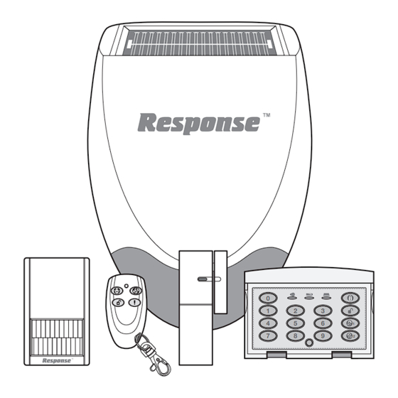
Page 4: Kit Contents
KIT CONTENTS The Alarm System should contain the following devices. Solar Siren Remote Control PIR Movement Detectors Door / Window Detectors Keypad Also included: Siren Mounting Template Installation & Operating Manual Fixing Pack Batteries Please Note: An installation video is available on-line at www.friedlandproducts.com Solar Siren PIR Movement... -
Page 5: Introduction And Overview
INTRODUCTION AND OVERVIEW SYSTEM ARMING JAMMING DETECTION The system has an Instant-Arm and Delay-Arm mode. In order to detect any attempts to illegally jam the radio channel used by your alarm system, a special If the system is armed in Instant-Arm mode then all jamming detection function is incorporated into the detectors will immediately become fully armed. -
Page 6: Planning And Extending Your Alarm System
PLANNING AND EXTENDING YOUR ALARM SYSTEM Before attempting to install your alarm system it is the Siren, Keypad, PIR and Magnetic Door / Window important to study your security requirements and Detectors for optimum security. Use this as a plan your installation. guide for your installation in conjunction with the detailed positioning requirements for each PIR Movement Detectors are used to protect the... -
Page 7: Remote Control Unit
REMOTE CONTROL UNIT (Optional Accessory) The Remote Control Unit(s) is used to Arm in either Arm or Part Arm modes and to Disarm the system. Insert a small coin into the Transmit LED Instant-Arm slot on the edge of the housing to gently lever open Disarm Delay-Arm... -
Page 8: Positioning The Keypad
The Keypad is powered by a PP3 Alkaline battery installation is complete, (see page 19). If the Siren which under normal conditions will have an expected Unit is being installed and configured for the first life of approximately 1 year. When the battery level time refer to pages 10 - 12. -
Page 9: Changing The User Access Code
Connect the PP3 alkaline battery to the battery Enter a new User Access Code of your choice: clip and set the jumper link J1 shown in Fig. 1a which is what the keypad is set to normally. New User Access Code Replace the rear cover and refit fixing screws. -
Page 10: External Solar Siren
Set the jumper link as shown in Fig. 1b. (below). POSITIONING THE SOLAR SIREN The Siren should be located as high as possible in Refit the battery and test it by entering the a prominent position on an external wall so that it Administrator Access Code 1234. -
Page 11: Power-Up Of The Solar Siren
Siren Switch SW3 ALARM TIME Tamper Switch ALARM TIME ALARM SOUND ALARM SOUND Learn BEEP SOUND BEEP SOUND C.U. OR SIREN Learn C.U. OR SIREN Switch 7.5 Volt DC charging 9 Volt startup adaptor input battery 6 Volt 1.2Ah Wall mounting plate rechargeable battery POWER-UP OF THE SOLAR SIREN... -
Page 12: Adding A New Remote Control Or Keypad To The Solar Siren
ADDING A NEW REMOTE CONTROL OR 13. To program the Remote Keypad’s ID code into KEYPAD TO THE SOLAR SIREN the Siren repeat step 11: a) Press IMPORTANT: In order to communicate with the New Keypad User Access Code Siren, the ID code of the Remote Control / Keypad needs to be learned by the Siren. -
Page 13: Mounting The Solar Siren On To The Wall
MOUNTING THE SOLAR SIREN ON PASSIVE INFRA-RED (PIR) TO THE WALL MOVEMENT DETECTORS 16. Hold the clear plastic mounting template supplied PIR Detectors detect movement in a protected area in position and mark the positions of the four by detecting changes in infra-red radiation levels mounting holes. -
Page 14: Installing And Configuring The Pir Detectors
INSTALLING AND CONFIGURING THE PIR DETECTORS Note: If adding a PIR Detector to an installed system, ensure that the Siren is in Service Mode before 10 11 commencing installation, (see page 19). Remember Detector Range (metres) to switch the Siren back to Operating Mode after installation is complete, (see page 19). -
Page 15: Testing The Pir Detectors
to normal operation. On initial installation the detector should be configured into Walk Test ready for testing, (i.e. Pressing down SW1 for 2 seconds). Sensitivity SW1 (Test Mode) Press for 2 seconds to activate Walk Test mode Test Mode (Test Mode) (Tamper) Refit the PIR Detector to the rear cover by (Sensitivity) -
Page 16: Magnetic Door / Window Detectors
MAGNETIC DOOR / WINDOW Ensure that the position selected for the Door / Window Detector is within effective range of the Siren. DETECTORS Do not fix the Detector onto or very close to The Magnetic Door / Window Detector comprises of metalwork (i.e. - Page 17 The Detector and Magnet should be mounted Switch SW3 is used to enable / disable the using the double sided adhesive pads or screws internal / external wired magnetic contact. provided. Note: If mounting the device using the adhesive Location of pads, ensure that the mounting surfaces are Key-hole Screw (underside)
-
Page 18: Testing The Door / Window Detectors
TESTING THE DOOR / WINDOW ADDING A NEW PIR OR DETECTOR MAGNETIC (MAG) DOOR / Remove battery cover to activate the tamper WINDOW CONTACT switch. DETECTOR TO THE SIREN As the button is released the LED indicator will illuminate for approximately 1 second to show IMPORTANT: In order to communicate with the that the tamper switch has been triggered and a Siren, the ID code of the Detector needs to be... -
Page 19: Deleting All Devices From The System
b) Confirm the new device ID code by The siren can be switched between Service Mode activating the Tamper Switch again on the and Operating Mode using any linked Remote PIR/MAG detector within 15 seconds. Control or Keypad as follows: The siren will produce three short low Remote Control: volume beeps and the Indicator / Learn... -
Page 20: Testing The System
TESTING THE SYSTEM The system should be tested at regular intervals (at Stop the alarm and Disarm the system by least every 3 months), to ensure that it is operating entering your User Access Code followed by the correctly. ‘DISARM’ button on the Keypad. Before commencing testing please ensure the following: User Access Code... -
Page 21: Operating Instructions
OPERATING INSTRUCTIONS When leaving the premises, the system must be ARMING THE SYSTEM IN Armed. However, before doing so, check that all INSTANT- ARM MODE windows are closed and locked, all protected doors The system can be Armed in Instant mode by using are closed and PIR Detectors are not obstructed. -
Page 22: Disarming The System
DISARMING THE SYSTEM The Alarm will sound until the set alarm duration time expires or the system is Disarmed from the The system can be Disarmed using either the Remote Control or Keypad. Remote Control or the Keypad as follows: SIREN SERVICE MODE Remote Control: In order to remove the Siren from the wall to change... - Page 23 Remote Keypad When the battery is low the ‘low-batt’ LED on the keypad will be illuminated. Note: The Keypad will retain your User Access Code setting for approximately 15 seconds whilst the battery is removed and replaced. If the battery is left disconnected for a longer period, or has been allowed to run completely flat your User Access Code will revert to the factory set code of “1 2 3 4 ”...
-
Page 24: Maintenance
MAINTENANCE operating and triggering an alarm, (see page 19). The Siren must be switched back into Operating Your Alarm System requires very little maintenance. Mode, otherwise the system cannot be Armed. However, a few simple tasks will ensure its continued reliability and operation. -
Page 25: Trouble Shooting
TROUBLE SHOOTING Symptom / Recommendation Siren immediately sounds when system 5. Siren rechargeable battery discharged: armed. a. Clean Solar Panel. 1. Siren tamper switch activated - adjust tamper b. Check age of rechargeable battery - replace plunger and ensure that switch fully closes when if at end of useful life. - Page 26 PIR Movement Detector not detecting a 6. If an additional wired Magnetic Contact is person’s movement. connected: a. Check that both contacts are closed. 1. Ensure the battery clip is securely connected. b. Check that additional contact is correctly wired 2.
-
Page 27: Extending Your Alarm System
If an item develops a fault, the product must be returned to the point of sale with: 1. Proof of purchase. 2. A full description of the fault. 3. All relevant batteries (disconnected). Response is a trademark of Novar ED&S. -
Page 28: Component Specification
COMPONENT SPECIFICATION External Solar Siren Keypad Magnetic Door / Window Detector(s) RF operating frequency: 868MHz RF operating frequency: 868MHz RF operating frequency: 868MHz Sealed lead acid battery Range: 125 metre max. Range: 150 metre max. 6V /1.2Ahr Changeable 4 digit User Access Test Mode Solar Panel 7.5V - Charge Rate Code.
Need help?
Do you have a question about the SL2 and is the answer not in the manual?
Questions and answers
how to put alarm into test mode
To put the Response SL2 alarm into test mode:
1. Ensure the siren is in Service Mode. If it is not, press and hold the button on the siren for 5 seconds until it emits one long beep followed by two short beeps. The LEDs will flash in sync with the beeps.
2. The siren automatically starts in Service Mode when first powered up.
3. The system should be tested regularly (at least every 3 months).
4. To stop the alarm and disarm the system after testing, enter your User Access Code followed by the ‘DISARM’ button on the Keypad.
This answer is automatically generated
MY SL2 alarms keypad is not working I need to help someone to come up and fix it
To fix a keypad issue on your Response SL2 alarm system, follow these steps:
1. Check the Battery: If the “LOW BATT” LED is flashing, replace the PP3 Alkaline battery.
2. Ensure Proper Mounting: The keypad should be installed in a protected area near the main entrance, avoiding metal objects that might interfere with the signal.
3. Reinstall the Keypad:
- Undo and remove the fixing screw from the bottom edge.
- Remove the wall mounting plate.
- If needed, remove and reinstall the rear battery cover.
4. Reset the Keypad:
- If the battery was already installed, remove it.
- Press and hold any key for more than 1 second.
- Set the jumper link J1 as required.
5. Ensure Proper Communication with the Siren:
- If adding a new keypad, put the Siren in Service Mode.
- Program the keypad’s ID code into the Siren following the programming steps.
6. Verify Solar Siren Power: If using a solar siren, ensure it has received sufficient light to charge its battery before arming the system.
If the issue persists, recheck the installation and configuration steps.
This answer is automatically generated
My keypad is not working I need help
To fix a non-working keypad on a Response SL2, follow these steps:
1. Check the Battery: Ensure the PP3 Alkaline battery is installed and not depleted. If the "LOW BATT" LED is flashing, replace the battery.
2. Press Keys Firmly: When using the keypad, press the buttons firmly and within 5 seconds of each other.
3. Verify User Access Code: Ensure the correct User Access Code is entered. If incorrect, wait 10 seconds before retrying.
4. Reset to Factory Defaults (if necessary):
- Remove the battery.
- Press and hold any key for more than 1 second.
- Set the jumper link according to the manual.
- Reinsert the battery and test by entering the default code (1234).
5. Ensure Siren is in Operating Mode: If the Siren is in Service Mode, switch it to Operating Mode.
6. Check Radio Range: Ensure the keypad is within the effective range of the Siren and not near metal objects that may interfere with the signal.
If the keypad still does not work after these steps, additional troubleshooting may be required.
This answer is automatically generated
I need sl2 keypad my is broken
To replace a broken Response SL2 keypad:
1. Undo and remove the fixing screw from the bottom edge of the existing Keypad.
2. Remove the wall mounting plate.
3. Remove the rear cover of the Keypad.
4. Replace the broken Keypad with a new one, using the wall mounting plate as a template for fixing if needed.
5. Install a new PP3 Alkaline battery in the new Keypad.
6. Refit the rear cover and secure it with the fixing screw.
7. Program the new Keypad's ID code into the Siren by pressing the required sequence (step 11 in the manual).
Ensure the Siren is not in Service Mode during programming.
This answer is automatically generated
alarm does not bleep after setting alam or after deactivating alarm
The Response SL2 alarm may not bleep after setting or deactivating the alarm if it is in Service Mode, as the siren does not operate in this mode until a remote control or keypad is linked to it. Additionally, if the Alarm Lockout feature has been activated after three alarm triggers, the system will prevent further re-arming and responses. Another possible reason is a low battery status, as the system incorporates battery level monitoring, and depleted batteries may affect functionality.
This answer is automatically generated