
Related Manuals for Response SA1 E


Summary of Contents for Response SA1 E
- Page 1 S 1 E, S 1 E PLUS, S 1PF E and S 2 E larm Systems Installation and Operating Instructions...
-
Page 2: Table Of Contents
Contents Page No. Page No. Kit Contents External Solar Siren Choosing a Location for the Solar Siren Introduction and Overview Installing the Solar Siren System rming Setting the Solar Siren Entry/Exit Delay Initial Power-Up of the Solar Siren larm Lockout Siren Service Mode Tamper Protection Siren Operating Mode... -
Page 3: Kit Contents
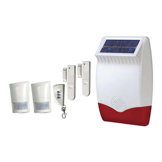
Kit Contents larm System S 1 E S 1 E PLUS S 1PF E S 2 E lso included: Components included: Installation & Operating Instructions External Solar Siren Fixing pack Remote Control PIR Movement Detectors Magnetic Contact Detectors Remote Keypad Batteries included: The type and number of each battery included will depend upon the components included in the System purchased. -
Page 4: Introduction And Overview
Introduction and Overview System rming for more than 30 seconds or if the system is jammed for more than 3 periods of 10 seconds in a 5 minute The system has an Instant- rm and Delay- rm mode. period. (The Siren will emit a series of rapid beeps If the system is armed in Instant- rm mode then all for 5 seconds as a pre-alarm warning 10 seconds detectors will immediately become fully armed. -
Page 5: Planning And Extending Your Wirefree Larm System
Planning and Extending your Wirefree larm System The example below shows a typical property Use this as a guide for your installation in conjunction incorporating the suggested positions for the with the recommendations contained in this manual Remote Keypad, PIR and Magnetic Detectors for for planning your intruder alarm system. -
Page 6: Remote Control Unit
Remote Control Unit Setting the Remote Control The Remote Control Unit is used to rm and Disarm the system. 1. Remove the front cover by undoing the small screw on the rear of the Remote Control. Transmit LED House Code Dip Switches Delay-Arm Slide up... -
Page 7: Remote Keypad
Remote Keypad Included in S 2 E system, available as Note: DO NOT fix the Remote Keypad to metalwork an optional accessory for the S 1 E, or locate the unit within 1m of metalwork (i.e. S 1 E PLUS and S 1PF E systems. radiators, water pipes, etc) as this could affect the radio range of the Remote Keypad. -
Page 8: Inputting The House Code
5. There are two jumper links located above the Note: Use thumb and middle finger to hinge off the battery compartment. cover. The Remote Keypad has a back light illumination facility. It will illuminate for 5 seconds when opening J2 jumper link: Reset to Factory default the cover or pressing any key. -
Page 9: Changing The User Ccess Code
4. Refit the battery and test it by using the default Testing the Remote Keypad User ccess code of 1 2 3 4. 1. Press 5. If the testing is ok, set the jumper link J2 as User Access Code shown on Fig. -
Page 10: Passive Infra-Red (Pir) Movement Detectors
Passive Infra-Red (PIR) Movement Detectors PIR Detectors are designed to detect movement The position of the PCB inside the PIR can be set to 5 in a protected area by detecting changes in different positions to adjust the range of the PIR infra-red radiation levels caused, for example, Detector. -
Page 11: Installing And Configuring The Pir Detector
Note: DO NOT fix the PIR Detector to metalwork or To adjust the PCB position, simply slide it up or locate the unit within 1m of metalwork (i.e. radiators, down ensuring that the location legs are aligned water pipes, etc) as this could affect the radio with the required position number marked on range of the device. -
Page 12: Testing The Pir Detector
3. DIP 4 of SW3 is used to configure the PIR 5. Connect the PP3 alkaline battery to the battery clip. Detector for walk test mode, which allows the Note: When the 9V alkaline battery is connected, operation of the Detector to be checked during the LED behind the lens will flash for 2-3 minutes installation without triggering a Full larm. -
Page 13: Magnetic Contact Detectors
Magnetic Contact Detectors The Magnetic contact comprises two parts; a Installing and Configuring the Detector and a Magnet. They are designed to be Magnetic Contact Detector fitted to doors or windows with the Magnet Ensure that the system is in Service Mode mounted on the opening part and the Detector mounted on the fixed frame. -
Page 14: Setting The Magnetic Contact Detector
3. DIP switches 9 -11 must be set as follows. (Ensure back surfaces DIP 9 DIP 10 DIP 11 are flush) Detector Magnet 4. If additional external contacts are wired to the Alternative Cut-out for Mounting Detector, remove the jumper link S2 on the PCB. Cable Entry Important: If external contacts are not connected Battery Cover... -
Page 15: External Solar Siren
External Solar Siren Choosing a Location for the Solar Siren The Siren & Strobe unit should be fitted to the outside of the building in a position that is clearly visible and at a height which is relatively inaccessible to an intruder. lthough the Siren &... -
Page 16: House Code
Front Cover Locating Tabs Solar Panel Receiver Aerial 7.5 Volt DC Charging Adaptor DIP Switch Input Cover Tamper Switch Beep Disable Link Siren Disable Link 6 Volt 1.2Ah Rechargeable Jamming Battery Detection Link 9 Volt PP3 House Code Initial Power-Up DIP Switches 1-8 Battery Printed Circuit... -
Page 17: Initial Power-Up Of The Solar Siren
Once you have completed setting the Solar Siren, refit Siren Service Mode the DIP switch cover and replace the three cover fixing In order to remove the Siren from the wall to change screws. Do not over tighten the screw as this could the batteries, it is necessary to place the Siren into damage the thread. -
Page 18: Testing The System
Testing the System Testing an Installed System If your system includes PIR Detectors: The system should be tested at regular intervals (at least rm the system in Instant- rm mode by pressing every 3 months) to ensure that it is operating correctly. on the Remote Control. -
Page 19: Operating Instructions
Operating Instructions When leaving the premises, the system must be rming the System rmed. However, before doing so, check that all windows are closed and locked, all protected doors are closed and PIR Detectors are not obstructed. The system can be set in RM mode using either the Ensure that pets are restricted to areas not Remote Control or the Remote Keypad as follows: protected by PIR Detectors. -
Page 20: Disarming The System
Disarming the System Enabling the Panic: The system can be disarmed using either the 1. Press Remote Control or the Remote Keypad as follows: 2. Enter Remote Control: User Access Code Press the button. 3. Press , the LED will illuminate The Siren will acknowledge the Disarm signal by once and flash twice beeping twice unless beep disable has been set. - Page 21 Remote Keypad: When the battery is low the ‘low-batt’ LED on the Remote Keypad will be illuminated. PIR Movement Detectors: Under low battery conditions the LED behind the detector lens will flash when movement is detected to indicate that the battery needs to be replaced. Under normal battery conditions the LED does not illuminate unless the PIR Detector is in Walk Test mode.
-
Page 22: Maintenance
Maintenance Your alarm system requireds very little maintenance. Detectors, Remote Control However, a few simple tasks will ensure its continued and Remote Keypad reliability and operation. The detectors require very little maintenance. The IMPORT NT: If, for any reason you have to completely batteries should be replaced once a year or when a power-down the Solar Siren (e.g. -
Page 23: Larm Record
larm Record You may make a note of your User ccess Code and System House Code below. User ccess Code System House Code e.g. = ON Use the above diagram to record your House ode This information is confidential and should be kept in a safe location. Notes:... -
Page 24: Troubleshooting
Troubleshooting ymptom / Recommendation ymptom / Recommendation Siren immediately sounds when system armed c. Fit new initial power-up battery and re-power up Siren 1. Siren tamper switch activated - adjust tamper 5. System locked - Reset system: plunger and ensure that switch fully closes when Siren is mounted. - Page 25 ymptom / Recommendation ymptom / Recommendation PIR Movement Detector not detecting a 6. If there is no additional wired Magnetic Contact person’s movement connected ensure the jumper link is fitted. 7. If an additional wired Magnetic Contact is 1. Ensure the battery clip is securely connected. connected: 2.
-
Page 26: Extending Your Larm System
Extending your larm System Your system may be extended to provide additional protection by adding further PIR Movement Detectors, Magnetic Contact Detectors and Remote Control Units. ccessories 433MHz 433MHz 433MHz 433MHz Wirefree Passive Infra-Red Wirefree Magnetic Wirefree Remote Wirefree Remote Keypad Movement Detector Contact Detector Control... -
Page 27: Notes
Notes:... -
Page 28: Component Specification
Technical Specification will be as stated. Customer Support Helpline: 0845 373 1353 (Local Call Rate - lines open 09.00 to 17.00 Monday to Friday) Response Electronics Ltd. Roman House, Lysons venue, sh Vale, Surrey GU12 5QF Email: info@responseelectronics.com...
Need help?
Do you have a question about the SA1 E and is the answer not in the manual?
Questions and answers