
Related Manuals for Response QC 3670


Summary of Contents for Response QC 3670
- Page 1 Installation and Operating Instructions These instructions should be retained in a safe place for future reference.
-
Page 3: Table Of Contents
CONTENTS 1. INTRODUCTION—3 2. KIT CONTENTS—6 3. INSTALLATION—8 3.1 Contents and Connections 8 3.2 Powering up the system 3.3 Setting the Camera Channel (Optional) 3.4 Pairing the Camera to Receiver (Optional) 3.5 Camera Installation 11 4. MONITOR PANEL INTRODUCTION—12 5. SYSTEM INTRODUCTION—13 5.1 Icon Functions 5.2 System Menu 6. -
Page 4: Introduction-3
1. INTRODUCTION The Digital Wireless Colour Camera Recordable CCTV Kit is a wireless security system designed to view and capture video clips of any motion viewed by the wireless camera and store them in on a memory card. The wireless camera supplied is colour, weatherproof and suitable for day/night use for the protection of your home or office, etc. - Page 5 PLANNING YOUR LAYOUT: Front Door Receiver TV/Monitor Camera 2 15mm diameter Camera 1 cable hole (to allow camera cable and connector Max 5m to pass through) Max 5m Ensure the distance from camera to power outlet does not exceed the length of the camera power adapter cable NOTE: The camera has an open field RF operating range of up to 150m.
-
Page 6: Night Vision
Camera(s) and DVR Do not attempt to open the units with the power adaptor plug connected to avoid any risk of personal injury. When installing CCTV camera(s), always follow manufacturer's advice when using power tools, steps, ladders, etc. and wear suitable protective equipment (e.g. safety goggles) when drilling holes. -
Page 7: Kit Contents-6
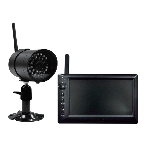
2. KIT CONTENTS 1 x 7" LCD Monitor (Receiver) 1 x Digital Wireless Cameras 2 x 5V/1A Power Adapter for Camera and Receiver 1 x Camera Stands 1 x Fixings Pack 1 x Video Playback PC Software(CD-ROM) 1 x AV Cable for TV Output 1 x Camera Antennas 1 x Manual Tools Required:... - Page 8 Digital Wireless Receiver Digital Wireless Camera Camera Stand 5V/1A Power Adapter for Camera and Receiver Video Playback PC Fixings Pack Software (CD-ROM) AV Cable Manual Digital Wireless Colour Camera Recordable CCTV Kit CWD3 Camera Antenna Installation and Operating Instructions These instructions should be retained in a safe place for future reference.
-
Page 9: Installation-8
3. INSTALLATION 3.1 Contents and Connections TV / MONITOR WIRELESS CAMERA Screw the Camera Bracket clockwise on to the lower body of the Camera to Wireless Cammera Video Signal to Input Camera Power Supply Adaptor WIRELESS RECEIVER Turn power on here Connect to Connect to 3.5mm Phone... -
Page 10: Powering Up The System
3.2 Powering up the system Insert the memory card into the DVR if not already fitted Press and Hold power key for one second to power hold the power. Press and hold the power key for two seconds to power off the system. After system power on, adjust the camera viewing position again if necessary. -
Page 11: Setting The Camera Channel (Optional)
3.3 Setting the Camera Channel (Optional) All wireless cameras will be supplied preset to channel 1. The wireless monitor supports up to 4 wireless cameras. Follow the step below to set or change the monitor channel of the camera. If you are adding another camera to link with the supplied monitor in this kit, then ensure its channel is set to a different channel to the existing camera(s). -
Page 12: Camera Installation
3.5 Camera Installation Attach Stand to Mounting Surface A.Secure camera stand on the wall B. Loosen the thumb screw C.Adjust the camera to the correct viewing position then secure the joint with T-bolt. -
Page 13: Monitor Panel Introduction-12
4. MONITOR PANEL INTRODUCTION Display Menu Playback REC Mode Other Link indicator Power indicator 3 Switch Channel Cursor UP Fast Forward VOL Down Cursor Left VOL Down Switch Display CH Menu OK / ENTER PLAY / PAUSE VOL Up Cursor Right VOL Up Switch Display CH 7 Switch Channel Cursor Down... -
Page 14: System Introduction-13
5. SYSTEM INTRODUCTION 5.1 Icon Functions 01-01-2011 AM12:54:29 (Display Icon) Signal Indicator Channel Indicator Recording Indicator Audio Channel Indicator Display mode QUAD Display Scan Display Single Display Audio Volume (Seven volume levels) = Full Volume = 1/2 Volume = Mute Receiver Power Indicator Power indicator will indicate 100% when adaptor in use IIII = 100% Strength... -
Page 15: System Menu
5.2 System Menu [Main Menu] Press MENU to enter main menu. After entering [MAIN MENU] system will highlight EVENT LIST by default. System will idle in [MAIN MENU] for 2 minutes before exiting [MAIN MENU]. Use ▲▼◄► to select, Press MENU to confirm selection and to enter sub-menu. CAMERA SETUP Press MENU to CAMERA SETUP Sub Menu RECORDER SETUP... - Page 16 EVENT LIST Press MENU to enter EVENT LIST SYSTEM SETUP Press MENU to enter SYSTEM SETUP ALARM BUZZER Press MENU to turn ALARM BUZZER ON / OFF for when motion is detected PAN TILT ZOOM Press MENU to enter single camera PAN TILT ZOOM mode...
-
Page 17: System Operation -16
SCAN ACTIVATED CAMERAS Press MENU to scan activated cameras in full screen mode. MEMORY CARD OVERWRITE Press MENU to set memory card overwrite ON or OFF. 6. System Operation 6.1 Camera Setup Select CAMERA SETUP, press MENU key once to enter sub-menu. - Page 18 Use▼▲to select the camera to set up (1-4). Use◄►to select [PAIRING] [BRIGHTNESS] [CAMERA ON/OFF] Camera Pairing With PAIRING section highlighted, press MENU key once to begin camera pairing (pair LED on camera will blink once and following with LED blinking continuously indicating data transmission in process.
- Page 19 Camera Brightness Adjustment With BRIGHTNESS section highlighted, use ▼▲ to adjust camera brightness. Press ESC to return to main menu. Camera Activation With ACTIVATION section highlighted, use ▼▲ to enable or disable camera. Press ESC to return to main menu. NOTE: Ensure the cameras are paired to the receiver for SCAN or QUAD to function properly (camera "ON"...
-
Page 20: Recorder Setup
6.2 Recorder Setup Record Schedule Use▲▼◄► to select and press MENU to enter schedule setup.There are three different recording options available to chose from. First highlight the time period and press MENU key to switch between different recording mode. M: MOTION (REC only when motion detected) S: SCHEDULE (continuous REC) X: MANUAL (manual REC) The system will record video from all 4 channels simultaneously with MOTION,... - Page 21 Motion Detection Sensitivity Select RECORDER SETUP, press MENU to enter. Use ▲▼ to select MOTION DETECTION SENSITIVITY section Use ◄► to highlight camera for setup Use ▲▼ to adjust sensitivity level: OFF / LV1 / LV2 / LV3 (LV3 is most sensitive) Press ESC to save and exit Format Memory Card Select RECORDER SETUP, press MENU to enter...
-
Page 22: Event List
Record Time Select RECORDER SETUP, press MENU to enter. Use ▲▼ to select RECORD TIME section Use ◄► to highlight recording period: 2 Min / 5 Min / 10 MIN, press MENU to confirm Press ESC to save and exit 6.3 Event List Playback Use ◄►... - Page 23 (1) Starting / Time: Start Time = PM10:33 End Time = PM10:43 (2) The type of recorded file (Schedule / Motion / Manual) is indicated by: = Channel 1 is SCHEDULE recorded file = Channel 1 is MOTION recorded file PM 10:33 =Channel 1, 2, 3 and 4 are MANUAL (C = Continous) recorded files PM 10:43...
-
Page 24: System Setup
6.4 System Setup Date and Time Select SYSTEM SETUP, press MENU to enter. Use ▲▼ to highlight DATE AND TIME, press MENU to enter. Use ◄► to highlight adjust: YEAR / MONTH / DATE / HOUR / MINUTE, use ▲▼ to adjust each section and press MENU to confirm adjustment. - Page 25 Power Saving (5 Minutes) (10 Minutes) (Always ON) Select SYSTEM SETUP, press MENU to enter. Use ▲▼ to select POWER SAVING Use ◄► to select SCREEN OFF AFTER 5 MINUTES IDLE / SCREEN OFF AFTER 10 MINUTES IDEL / SCREEN ALWAYS ON, press MENU to confirm setting. Press ESC to save and exit.
- Page 26 (Display QUAD mode) (5 sec Intervals) (10 sec Intervals) (15 sec Intervals) Select SYSTEM SETUP, press MENU to enter. Use ▲▼ to select MULTI CHANNELS IDLE DISPLAY. Use ◄► to select: DISPLAY QUAD DURING IDLE / AT 5 SEC INTERVALS / AT 10 SEC INTERVALS / AT 15 SEC INTERVALS, press MENU to confirm selection.
-
Page 27: Alarm Buzzer
Default Select SYSTEM SETUP, press MENU to enter. Use ▲▼ to select DEFAULT. Use ◄► to select the system language for SYSTEM RESTORE, press MENU to confirm selection and system will restore to factory default. NOTE: While SYSTEM RESTORE icon highlighted, system firmware version will be displayed (example: VER:11.06.11-21:13:09) 6.5 Alarm Buzzer Select ALARM BUZZER, press MENU to turn buzzer ON or OFF. -
Page 28: Pan Tilt Zoom
6.6 Pan Tilt Zoom Select PAN TILT ZOOM, press MENU once to enter ZOOM mode, press MENU again to zoom in (2X). When zooming in, use ▲▼ ◄► to select various view areas. Press MENU to zoom out. In zoom out (1X), use ▲▼to change available channel Press ESC to exit ZOOM. -
Page 29: Memory Card Overwrite
6.7 Memory Card Overwrite When the memory is full, by enabling this function will allow you to overwrite the earlist files with the recent ones. Select MEMORY CARD OVERWRITE, press MENU once to activate overwrite function and press MENU again to de-activate. NOTE: (1) One of the following examples will appear on display screen a. -
Page 30: Sec24 Media Player Introduction
7.PLAYBACK SOFTWARE Sec24 Media Player is specifically designed to playback recorded files from the Digital Wireless Colour Camera Recordable CCTV Kit you have purchased on PC. Others cannot playback recorded files without Sec24 Media Player; this is for you privacy protection. 7.1 Sec24 Media Player Introduction Channel 1 Playback Screen Channel 2 Playback Screen... -
Page 31: Installation
7.2 Installation Insert CD came with the package into the CD-ROM on PC. Click on MY COMPUTER, double click on the drive where the CD-ROM assigned by PC (for example: E;\). In E drive you will find the following icon. Please follow installation procedure A to X to complete installation. - Page 32 (2) Following error message will appear if user did not select “Run as administrator” option first before starting the installation. A. Double click the icon to start installation process.
- Page 33 B. Click “Next” and following window will appear on screen. Following window will appear on screen after installation completes. Click “Finish” to complete the installation.
-
Page 34: Playback Recorded File(S)
7.3 Playback Recorded File(s) Double click Sec24 Media Player icon on desktop to start software... - Page 35 Click on “Load” to import and playback previous recorded files (SNX files) already stored on...
-
Page 36: Channel Disable / Enable Select
7.4 Channel Disable / Enable Select During playback, all four channels will playback at once. For privacy concern, user is able to manually disable audio channel and/or video channel(s). Select Audio to turn off sound • Select 1 to turn off video image from channel 1 •... -
Page 37: System Configuration
8. System Configuration Channel 1 Activation Channel 2 Camera Setup Brightness Channel 3 Pairing Channel 4 Schedule Cam1 Cam2 Cam3 Cam4 Motion sensitivity SD Card Format Recorder Setup Cam1 Cam2 Cam3 Cam4 Motion Area 2 minute 5 minutes 10 minutes Record Time Event List Play Mode... -
Page 38: Product Specification
9.Product Specification Camera Receiver Maximum Channels Communication Range 150 metres in open space Monitor Resolution 800X480 Camera Resolution 640X480 Operating Temperature -10°C ~ 50°C Operating Voltage DC 5V / 1A Curren Consumption 550mA(max) 860mA(max) Night Vision 5-8m Dimension 130x61x67 mm 200x122x25 mm 10.Total Recording Time for Memory Cards (32GB max.) Micro SD Card Capacity...
Need help?
Do you have a question about the QC 3670 and is the answer not in the manual?
Questions and answers