
Related Manuals for Response SA3 E PLUS


Summary of Contents for Response SA3 E PLUS
- Page 1 S 3 E PLUS 6 Zone Wirefree larm System with Voice Dialler Installation and Operating Instructions...
-
Page 2: Table Of Contents
Contents Page No. Page No. Kit Contents Hard-Wired Solar Siren Test Testing the System (continued) Introduction and Overview Solar Siren Test System rming Control Panel LED Test Zones Solar Siren Service Mode Entry/Exit Delay Voice Dialler Test Zone Lockout Factory Defaults Tamper Protection Reset Factory Default Conditions Voice Dialler... -
Page 3: Kit Contents
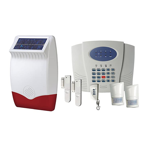
Kit Contents larm Components: Batteries included: 1 x 6 Zone LED Control Panel with Voice Dialler 2 x PIR Movement Detectors 6V/1.2 hr Sealed lead acid 2 x Magnetic Contact Detectors battery (for ontrol Panel and 1 x Remote Control External Solar Siren) 1 x External Solar Siren lso included:... -
Page 4: Introduction And Overview
Introduction and Overview System rming Delay rmed zones will not become fully armed until after the Exit delay period has expired. When a The system has a ‘Full rm’ and a ‘Part- rm’ mode. Detector on a Delay rmed zone is triggered, an alarm ‘Full rm’... -
Page 5: Jamming Detection
sequence and replay the recorded alarm messages for System House Code the set ‘Play Time’. The recipient can acknowledge In order to prevent any unauthorized attempt to the message by pressing the button on their operate or disarm your system, you must set your telephone keypad. -
Page 6: Planning And Extending Your Wirefree Larm System
Planning and Extending your Wirefree larm System The example below shows a typical property Use this as a guide for your installation in conjunction incorporating the suggested positions for the with the recommendations contained in this manual Control Panel, PIR and Magnetic Detectors for for planning your intruder alarm system. -
Page 7: Control Panel
Control Panel Zone LEDs ZONE FIRE TAMPER Status LEDs Keypad External view of Control Panel Positioning the Control Panel 6. If the telephone voice dialler is to be used then the Control Panel will need connecting to a convenient When choosing a suitable location for the Control telephone point. - Page 8 Power Supply External Tamper Switch Cable Route Jumper Link P51 Upper Keyhole Upper Fixing Hole Keyhole Fixing Hole - Terminal (Blue Lead) + Terminal (Blue Lead) + Terminal (Red Lead) - Terminal (Black Lead) Lower Fixing Hole Reset Jumper Link P1 Power Supply Jack...
-
Page 9: Setting The Control Panel House Code
Connect the BT plug on the other end of the lead b) Press to return to programming mode to an appropriate telephone outlet. without saving. If the cable supplied is not long enough to reach a Using a Remote Control Unit: suitable phone point then it will need extending a) With the required House Code already set on using a coupler and extension lead (not supplied). -
Page 10: Setting The Remote Control
The Remote Control uses a CR2032 type Lithium cell If movement is detected an alarm signal will be which under normal conditions will have a typical life generated, (if the system and alarm zone is armed). in excess of 1 year. Under normal battery conditions Note: PIR Detectors will also detect animals, so the LED on the Remote control will illuminate only... -
Page 11: Installing And Configuring The Pir Detectors
When considering and deciding upon the mounting Rear Cover position for the PIR Detector the following points should be considered to ensure trouble free operation: Mounting Hole Positions 1. Do not locate the PIR Detector facing a window or where it is exposed to or facing direct sunlight. PIR Detectors are not suitable for use in conservatories. -
Page 12: Testing The Pir Detectors
Note: On initial installation the PIR Detector should 11. Refit the PIR Detector to the rear cover by offering be set into Walk Test mode ready for testing. the PIR Detector up to the rear cover and locate the clips in the top edge into the rear cover. Push the 8. -
Page 13: Magnetic Contact Detectors
Magnetic Contact Detectors (Ensure Installing and setting the Magnetic back Contact Detectors surfaces are flush) Ensure that the system is in Test mode. Magnet Detector 1. Remove the battery cover by sliding and lifting it Alternative off. (DO NOT use a screwdriver to lever off). Cut-out for Mounting Cable Entry... -
Page 14: Testing The Magnetic Contact Detectors
8. Slide the two batteries supplied into the battery External Solar Siren holder, ensuring that the positive (+) side is uppermost on each battery as it is installed. The Siren and Solar Panel are all encapsulated within a tough polycarbonate housing. This housing provides 9. -
Page 15: Installing The Solar Siren
North Installing the Solar Siren Avoid if possible 1. Remove the fixing screw from the bottom edge of the Solar Siren Siren housing and carefully hinge off the front cover. ll electronic components are housed within the front cover. West East 2. -
Page 16: Setting The Solar Siren
Setting the Solar Siren Once you have completed configuring the Solar Siren, refit the DIP switch cover and replace the three cover Ensure that the Solar Siren main configuration switch fixing screws. Do not over tighten the screw as this if fitted on the LED strobe board is set to “SIREN”... -
Page 17: External Connections
single long beep/LED flash followed immediately Control Panel cover and tighten the fixing screws on by two short beeps/LED flashes to indicate that it the top edge of the Control Panel. has switched into Service Mode. Press to leave Test mode and return to Standby. Operating Mode: Press and hold the button on the Remote Control. -
Page 18: Hard-Wired Solar Siren Test
Hard-Wired Solar Siren Test Factory Defaults Press User ccess Code 1 2 3 4 The internal relay driving the hardwired siren will be larm Duration 3 minutes switched ON for a period of approximately 5 seconds. Hardwired Siren Equal to larm Duration Zone LED 2 will be illuminated during the test. -
Page 19: Programming Instructions
Programming Instructions Press b) Using a Remote Control: With the required House Code already set in the User Access Code remote, press the DIS RM button on the Remote rm and Part- rm LEDs will illuminate and all Control. Zone, Fire and tamper LEDs will flash. The Control Panel will beep twice to acknowledge The system is now in Programme Mode the signal. -
Page 20: Larm Duration
Press the key corresponding to the required delay Part- rm setting required, the corresponding zone LED will Default setting: Zone 1 Disabled illuminate as the setting is changed. Zones 2-6 ctive Press to save the new setting and return to Press programming mode. -
Page 21: Entry/Exit Warning Tone
Entry / Exit Warning Tone Hard-Wired Siren Default setting: ON Default setting: equal to larm Duration Press Press The zone 1 LED will illuminate to indicate the current The zone LED corresponding to the current setting status of the Entry/Exit warning tone. will illuminate. -
Page 22: Telephone Numbers
Note: Panic switch, 24 Hour Intruder and Fire modes Press to save the new number and return to all operate on a 24 hour basis, (i.e. they are able to programming mode. initiate a Full larm condition at any time irrespective Press to return to programming mode without of whether the system is rmed or Disarmed). -
Page 23: Replay Larm Message
Replay larm Message Call ttempts The recorded alarm message may be replayed and This is the total time for which the alarm messages will listened to using the telephone handset of a phone be played & repeated when a call made by the voice connected to another extension socket on the same dialer is answered. -
Page 24: Operating Instructions
Operating Instructions When leaving the premises, the system should be rming the System rmed. However, before doing so, check that all windows are closed and locked, all protected doors are closed and PIR Detectors are not obstructed. The system can be set in RM mode using either the Ensure that pets are restricted to areas not protected Remote Control or the Control Panel as follows: by PIR Detectors. -
Page 25: Disarming The System
Disarming the System Tamper The system can be disarmed using either the Remote If the battery cover of any device (except a Remote Control or the Control Panel as follows: Control) is removed or if the Solar Siren or Control Panel are removed from the wall then a Full larm Remote Control:... -
Page 26: Maintenance
PIR Movement Detector: Batteries Under low battery conditions the LED behind the Before removing the battery cover on any device or Detector lens will flash when movement is detected to opening the Control Panel to replace the battery indicate that the battery needs to be replaced. ensure that the system is put into Test mode to avoid initiating a Full larm condition. -
Page 27: Larm Record
larm Record Complete the following information during installation for future reference when adding to your system and to assist Trouble Shooting Zone Settings. Zone Settings Zone Instant / Zone Detector(s) Location Operating Part- rm Delay Mode You may make a note of your User ccess Code and System House Code below. User ccess Code System House Code = ON... -
Page 28: Troubleshooting
Troubleshooting ymptom / Recommendation ymptom / Recommendation Control Unit not working – Power LED OFF Detection Zone triggered (LED flashing) but no alarm is sounding 1. Mains power failure – check if other electrical circuits are operable. 1. Entry/Exit delay still running and not yet expired. 2. - Page 29 ymptom / Recommendation ymptom / Recommendation PIR Movement Detector not detecting a Note: If an additional contact is used then the person’s movement doors / windows protected by both the main wirefree Detector and the additional wired 1. Check battery connections are good. Detector must be closed when either is opened.
-
Page 30: Extending Your Larm System
Extending your larm System Your system may be extended to provide additional protection by adding further PIR Movement Detectors, Magnetic Contact Detectors and Remote Control Units. ccessories 433MHz 433MHz 433MHz 433MHz Wirefree Passive Infra-Red Wirefree Magnetic Wirefree Remote Wirefree Remote Keypad Movement Detector Contact Detector Control... -
Page 31: Notes
Notes:... -
Page 32: Component Specification
Technical Specification will be as stated. Low battery indicator Customer Support Helpline: 0845 373 1353 (Local Call Rate - lines open 09.00 to 17.00 Monday to Friday) Response Electronics Ltd. Roman House, Lysons venue, sh Vale, Surrey GU12 5QF Email: info@responseelectronics.com Web: www.ResponseElectronics.com...
Need help?
Do you have a question about the SA3 E PLUS and is the answer not in the manual?
Questions and answers