GE MDS SD Series Reference Manual
Secure, long range ip/ethernet & serial
Hide thumbs
Also See for MDS SD Series:
- Technical manual (124 pages) ,
- Quick start manual (4 pages) ,
- Setup manual (4 pages)

Related Manuals for GE MDS SD Series


Summary of Contents for GE MDS SD Series
- Page 1 MDS SD Series Secure, Long Range IP/Ethernet & Serial Covering ES/SS Units Operating in Transparent and Packet Modes with Firmware Version 3.x MDS 05-4846A01, Rev. C DECEMBER 2009...
- Page 2 Need Quick-Start instructions for this product? Please refer to publication 05-4847A01. All GE MDS user guides are available online at www.gemds.com...
-
Page 3: Table Of Contents
TABLE OF CONTENTS 1.0 INTRODUCTION ........................1 1.1 Conventions Used in This Manual ....................1 1.2 Electronic Manuals ........................2 2.0 PRODUCT DESCRIPTION....................3 2.1 Front Panel Connectors and Indicators ..................3 2.2 Key Product Features ........................4 2.3 Model Offerings ..........................4 2.4 Operating Modes and Applicable Manuals .................. - Page 4 Inter-Packet Gap Settings....................... 27 Baud Rate Setting........................27 Modem Type Setting ....................... 27 Ethernet Settings ........................28 MANAGING THE TRANSCEIVER..................29 6.1 Menu Access ..........................29 6.2 Menu Structure ..........................30 6.3 Menu Navigation ......................... 30 6.4 Logging Out of the Menu System ....................30 6.5 Task-Oriented Menu Chart ......................
- Page 5 Detailed Command Descriptions ..................122 Copyright and Trademark This manual and all software described herein is protected by Copyright: 2009 GE MDS, LLC. All rights reserved. GE MDS, LLC reserves its right to correct any errors and omissions in this publi- ® cation. Modbus is a registered trademark of Schneider Electric Corporation.
-
Page 6: Environmental Information
These systems will reuse or recycle most of the materials found in this equipment in a sound way. Please contact GE MDS or your supplier for more information on the proper dis- posal of this equipment. - Page 7 Test Data Sheets showing the original factory test results for this unit are available upon request from the GE MDS Quality Leader. Contact the factory using the information at the back of this manual. Serial numbers must be provided for each product where a Test Data Sheet is required.
- Page 8 SD Series Ref. Manual (Packet & Transparent Mode) MDS 05-4846A01, Rev. C...
-
Page 9: Introduction
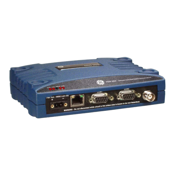
1.0 INTRODUCTION This Reference Manual is one of two books provided for users of the MDS SD Series Transceiver (Figure 1). It contains an overview of common applications, installation planning data, technical specifica- tions, troubleshooting, and a listing of software menus. This manual should be available to technical personnel who perform network design, configuration, and troubleshooting of the equipment. -
Page 10: Electronic Manuals
Model Number The term “SD” or “SD Series” is used in this manual to denote all Notations models in the SD product line. Specific model numbers such as MDS SD2 (216-235 MHz), MDS SD4 (350-512 MHz), and MDS SD9 (928-960 MHz) are used only when necessary to reference model-spe- cific features. -
Page 11: Product Description
2.0 PRODUCT DESCRIPTION The SD Transceiver is a software-configurable, industrial radio for use in licensed poll-response telemetry networks. It may be interfaced with a variety of data control equipment including remote terminal units (RTUs), programmable logic controllers (PLCs), flow computers, and similar devices. -
Page 12: Key Product Features
2.2 Key Product Features The transceiver is designed to meet the demanding needs of today’s industrial wireless networks in a compact, rugged package. It offers an array of features in one hardware platform: • Ethernet & serial interfaces—ideal for migration to IP networks •... -
Page 13: Operating Modes And Applicable Manuals
2.4 Operating Modes and Applicable Manuals The transceiver may be configured to operate in any one of three modes: • Packet Mode—Payload data from the radio’s serial or Ethernet ports is assembled into packets and transmitted over the air. Packet mode supports Ethernet Bridging, AES 128-bit encryp- tion, and multihost operation. -
Page 14: Accessories And Spares
2.5 Accessories and Spares Table 1 lists common accessories and spare items for the transceiver. GE MDS also offers an Accessories Selection Guide listing an array of additional items that may be used with the product. Contact your factory representative or visit to obtain a copy of the guide. -
Page 15: Typical Applications
A number of variations are possible, and if you have unique requirements not covered here, it is recommended that you con- sult a support specialist at GE MDS. Contact information is provided at the back of this manual. -
Page 16: Multiple Address Systems (Mas)
Table 2. Application Types vs. Key Radio Settings (Continued) Radio Application Protocol CSMA (LBT) Multihost Notes Mode Generic Bridged Packet ON or OFF Listen on RX EThernet (ICMP/TCP/UDP) Mixed Serial and Modbus RTU & IP Packet ON or OFF Listen on RX Optional ON if messages Bridged Ethernet... -
Page 17: Point-To-Point System
Point-to-Point System Where permitted, the transceiver may also be used in a point-to-point arrangement. A point-to-point system consists of just two radios—one serving as a master and the other as a remote (see Figure 5). It provides a simplex (or half-duplex) communications link for the transfer of data between two locations. -
Page 18: Ip Polling Of Serial Remotes
IP Polling of Serial Remotes The transceiver is ideal for use in systems employing a mix of serial and Ethernet protocols. While many variations are possible, Figure 7 shows a typical scenario with an Ethernet host at the Master Unit that is polling serial-based RTUs at the Remote sites. -
Page 19: Port Sharing With Multiple Hosts
In such a system, each RTU gets every message from the host computer, and the underlying protocol (e.g., Modbus, DNP, etc.) must sort out which messages are applicable to a specific RTU. Ethernet Data Port Menu MASTER RADIO To Ethernet Port HOST COMPUTER TCP Ethernet (Host A) -
Page 20: Installation Planning
At the Remote sites, serial and Ethernet-based RTUs are employed, and responding to a specific host computer. In the case of the Remote shown on the lower right side of the drawing, two RTUs are co-located, but responding to different host computers and handling entirely different streams of data. -
Page 21: Mounting Options
ANTENNA SYSTEM Master Stations typically use omni-directional antenna TRANSCEIVER POWER SUPPLY 10.5–16 VDC @ 2.5A Negative Ground Only DATA TELEMETRY DEVICE OR HOST COMPUTER Figure 10. Typical Remote Station Arrangement 4.1 Mounting Options The transceiver is normally provided with flat mounting brackets attached to the bottom of the radio as shown in Figure 11. -
Page 22: Optional Din Rail Mounting
Antennas of this type are available from several manufacturers, including GE MDS. Contact your factory representative for details. SD Series Ref. Manual (Packet & Transparent Mode) MDS 05-4846A01, Rev. C... -
Page 23: Feedlines
Invisible place holder Figure 13. Typical Yagi Antenna (mounted to mast) Feedlines The selection of an antenna feedline is very important. Poor quality cable should be avoided as it will result in power losses that may reduce the range and reliability of the radio system. Table 4, Table 5, and Table 5 show the approximate losses that will occur when using various lengths and types of coaxial cable in the 200, 400 and 960 MHz bands, respectively. -
Page 24: Dc Power Connection
Table 5. Length vs. Loss in Coaxial Cables (at 960 MHz) 10 Feet 50 Feet 100 Feet 200 Feet Cable Type (3.05 Meters) (15.24 Meters) (30.48 Meters) (61 Meters) RG-8A/U 0.85 dB 4.27 dB 8.54 dB 17.08 dB 1/2 inch HELIAX 0.23 dB 1.15 dB 2.29 dB... -
Page 25: Serial Data Interfaces
Normally, the transceiver is adequately grounded if the supplied flat mounting brackets are used to mount the radio to a well-grounded metal surface. If the transceiver is not mounted to a grounded surface, it is rec- ommended that a safety ground wire be attached to one of the mounting brackets or a screw on the transceiver’s case. -
Page 26: Com2 (Data) Connections
> DB-9 MALE DB-9 FEMALE < (RADIO SIDE) (COMPUTER) Figure 16. COM1 Wiring for PC Management Table 6. COM1 Pin Descriptions Input/ Number Output Pin Description No function RXD (Received Data)—Supplies received data to the connected device. TXD (Transmitted Data)—Accepts TX data from the connected device. - Page 27 Table 7. COM2 Pin Descriptions—Radio in RS-232 Mode Input/ Number Output Pin Description DCD (Data Carrier Detect/Link)—A low indicates signal received. RXD (Received Data)—Supplies received data to the connected device. TXD (Transmitted Data)—Accepts TX data from the connected device. Sleep Mode Input—Grounding this pin places the radio in a low power consumption mode.
-
Page 28: Ethernet Data Interface (Rj-45)
• TXD+ / TXA and TXD– / TXB are data received by the radio and sent out • TXD+ / TXA is positive with respect to the TXD– / TXB when the line output is a “0” Invisible place holder EIA-422 4-WIRE CONNECTIONS EIA-485 2-WIRE CONNECTIONS TXD +... -
Page 29: Step-By-Step Installation
5.0 STEP-BY-STEP INSTALLATION In most cases, the steps given here are sufficient to install the trans- ceiver. Refer to “INSTALLATION PLANNING” on Page 12 for addi- tional details, as required. 1. Mount the transceiver. Attach the mounting brackets to the bottom of the transceiver case (if not already attached), using the four 6-32 x 1/4 inch (6 mm) screws supplied. -
Page 30: Initial Configuration
5.1 Initial Configuration This section provides the steps necessary to program the radio for its first on-air operation. There are numerous settings and menus that go beyond basic configuration, and you may wish to access these later. A full description of menu tasks is provided in Section 6.0 MANAGING THE TRANSCEIVER. - Page 31 Invisible place holder Transceiver PC Running Terminal Session DB-9M to COM1 Port Figure 20. PC Connection to Transceiver Press the key followed by a series of key presses (at ESCAPE ENTER . This indicates that half-second intervals) to receive the prompt Login: the radio is ready to receive commands.
- Page 32 Figure 21. Starting Information Screen (First screen displayed upon login) 7. Press to access the Main Menu (Figure 22). This is the gateway to all settable parameters of the radio. Menu selections are made by pressing the letter shown to the left of a item name. Figure 22.
- Page 33 8. Select from the Main Menu and then select Radio Configuration Basic . The screen shown in Figure 23 appears. Review these basic Settings settings to determine if they are appropriate for your system. • The default default setting is dBm (5 watts), RF Output Power but you may wish to set it lower if full power is not required for...
-
Page 34: Initial Startup & Checkout
5.2 Initial Startup & Checkout In-service operation of the transceiver is completely automatic. Once the unit has been properly installed and configured, operator actions are limited to observing the front panel LED indicators for proper operation. If all parameters are correctly set, operation of the radio can be started by following these steps: 1. -
Page 35: Optimizing The Radio Network
5.3 Optimizing the Radio Network Antenna SWR Check Before the radio is placed into final service, a check should be made of the antenna system’s standing wave ratio (SWR) using a directional wattmeter suited to the frequency of operation. High SWR (above 2:1) may indicate an antenna or feedline problem, and should be corrected. -
Page 36: Ethernet Settings
Ethernet Settings The local Ethernet connection should be configured to conform to the needs of the local Ethernet network. The IP Configuration Menu pro- vides access for TFTP reprogramming and saving/restoring configura- tion information. Additionally, if UDP/TCP data traffic is desired, the settings of the Ethernet Data Port will need to be configured. -
Page 37: Managing The Transceiver
MANAGING THE TRANSCEIVER This section covers the management and programming tasks that can be performed with the transceiver’s built-in menu system. A top level view of the menu tree is shown, as well as a chart listing commonly-needed tasks and the appropriate menu(s) to refer to. No attempt has been made to show every possible submenu of the trans- ceiver in this section. -
Page 38: Menu Structure
6.2 Menu Structure The transceiver menus are arranged in a hierarchal format based on the major tasks that can be performed. An overall view of the menu system is shown in Figure 25. 6.3 Menu Navigation When you first log in to the menu system, the Starting Information Starting Information Screen Screen appears with a summary of current operating conditions. - Page 39 Invisible place holder Figure 25. Menu System Overview MDS 05-4846A01, Rev. C SD Series Ref. Manual (Packet & Transparent Mode)
-
Page 40: Task-Oriented Menu Chart
6.5 Task-Oriented Menu Chart Table 11 is a task-oriented listing of user and maintenance tasks. To use the table, find the task you wish to perform, and then refer to the far right-hand column for the specific menu(s) to use. Additional coverage of menu tasks is provided in “Using the Menu System—Common Tasks”... - Page 41 Table 11. Menu Selection Chart (Continued) Task Refer to this If you wish to... Category Menu>>Submenu(s) Set RF Output Power, Modem Type, RX/TX Radio Configuration>> Frequency Basic Settings (See Figure 35 on Page 42) View/Set Soft-Carrier Dekey status, RX/TX Radio Configuration>> Time-Out options Advanced Settings (See Figure 36 on Page 44)
- Page 42 Table 11. Menu Selection Chart (Continued) Task Refer to this If you wish to... Category Menu>>Submenu(s) Configure the IP settings (Static IP Address, Ethernet Configuration>> Static IP Netmask, Static Default Gateway, IP Configuration DHCP enable/disable, Virtual Radio (See Figure 51 on Page 63) Channels–VRCs) Configure Ethernet Bridging Ethernet Configuration>>...
- Page 43 Table 11. Menu Selection Chart (Continued) Task Refer to this If you wish to... Category Menu>>Submenu(s) View Radio Performance data (Power Output, Radio Performance Signal-to-Noise Ratio, Received Signal (See Figure 38 on Page 50) Strength, DC Input voltage, operating temperature) Perform radio tests (Radio Keying, run Maintenance/Tools>>...
-
Page 44: Using The Menu System-Common Tasks
6.6 Using the Menu System—Common Tasks The transceiver is designed for rapid installation with a minimum number of menu configuration steps. In many cases, only the receive (RX) and transmit (TX) frequencies need to be set to begin basic opera- tion. - Page 45 Figure 26. Starting Information Screen Radio Performance (Figure 27) is another source of real-time Radio Performance Menu Menu operating information for the transceiver. It is available directly from the Main Menu. Invisible place holder Figure 27. Radio Performance Menu This menu displays the radio’s RF output power, signal-to-noise ratio, received signal strength indication (RSSI), DC input voltage, and internal operating temperature.
- Page 46 Device Info Menu (Figure 28) shows additional read-only information Device Info Menu for the radio, including its serial number, hardware configurator string (Model 1) software configurator string (Model 2), firmware version, and build date. This menu is accessed by selecting Device Configura- from the Main Menu.
- Page 47 Statistics /Events From the (Figure 30), you can access submenus Statistics/Events Menu Menu showing current and logged alarms/events, I/O statistics, and Ethernet statistics. These submenus are continually refreshed to show the most current information. Invisible place holder Figure 30. Statistics/Events Menu submenu (Figure 31) shows a summary of current Alarms/Events alarms (major and minor), status conditions, the status of the Alarm...
- Page 48 The Event Log Menu (Figure 32) is used to display all events stored by the transceiver, even if the radio has been power-cycled. It also shows a running total of alarms stored. Select to view stored events, Show Log to erase all stored entries. For more information, see Page Clear Log Figure 32.
- Page 49 Invisible place holder Figure 33. I/O Statistics Menu (Example shows Statistics for COM1 Interface) Submenu (Figure 34) presents a detailed summary Ethernet Statistics of packets received and transmitted, dropped packets, errors, overruns of the buffer, RX data rate (bps), and RX/TX data for Unicast, Multicast, and Broadcast transmissions.
-
Page 50: View/Set Radio (Rf) Operating Parameters
6.7 View/Set Radio (RF) Operating Parameters RF Output Power Setting The RF output power of the transceiver may be set between 20 and 37 dBm (0.1 to 5 watts) in1 dB increments. The default setting is 37 dBm Full power is not required in many cases, and lower settings will place less demand on the DC power supply and may reduce the chance of interference with other stations. -
Page 51: Rx And Tx Frequencies
, but it may be set to any of the selections shown in Modem 9600 Table 12. The table also lists modem sensitivity ratings for the various modems. Note that some modem choices are limited based on the model purchased. Table 12. -
Page 52: Soft-Carrier Dekey Setting
1. Select from the menu and enter the receive frequency (in MHz) in the field to the right of the screen ( ). Press the xxx.xxx ENTER to apply the change. 2. Select from the menu and enter the transmit frequency (in MHz) in the field to the right of the screen ( ). - Page 53 RX Time-Out RX Time-Out protects against a receiver which fails to receive data for a period exceeding the time-out setting. When the time is exceeded, an alarm is issued. The alarm can be used to signal switchover to an alter- nate unit in redundant systems.
-
Page 54: Datakey Setting
Datakey Setting This setting determines whether or not the radio is configured to key (transmit) upon receipt of payload data at its interface port. The default setting is . To change the setting, proceed as follows: 1. Select from the menu and press the spacebar to change the Datakey setting to 2. -
Page 55: Switched Carrier Setting (B Modems Only)
Automatic Frequency Correction (AFC) Setting Automatic Frequency Correction (AFC), is used to counteract the slight RF frequency drift that may occur over time or through wide swings of ambient temperature. The default setting for AFC is . To change the setting, proceed as follows: 1. - Page 56 peer-to-peer configurations, may be preferred. Optimal Listen on TX choices depend on the data transmission characteristics of the connected system. This, and all other LBT parameters, are set using the LBT Set- tings Menu (Figure 37). Invisible place holder Figure 37. Listen Before Transmit (LBT) Settings Menu To activate the LBT feature, select the menu item, Enabling LBT and...
-
Page 57: View Received Signal Strength (Rssi)
1. Select the desired menu item ( Min Channel Wait Max Channel Wait The field to the right of the item clears and a flashing cursor appears. 2. Enter the desired wait time(s) in milliseconds and press the ENTER key to apply the change. Setting LBT Timeout The LBT menu provides a setting for the maximum time to wait (in mil- and Packet Action... -
Page 58: View/Set Device Configuration
Figure 38. Radio Performance Menu 6.8 View/Set Device Configuration Viewing Serial Number and Version Information The radio’s serial number and active firmware version are shown on the Starting Information Screen (Figure 39), which appears automatically at start-up, or by selecting Main Menu>>Starting Information Screen Version information may also be viewed on the Device Info Menu (Figure 40), which provides additional information, including the build... -
Page 59: Setting Owner Name/Message
Invisible place holder Figure 40. Device Info Menu To view detailed version information for both active and inactive firm- ware images, use the radio’s Version Menu (Figure 41). Navigation path: Maintenance/Tools Menu>>Version Menu Invisible place holder Figure 41. Version Menu Setting Owner Name/Message An owner name and message may be entered for the radio for informa- tional purposes. -
Page 60: Enabling/Disabling Sleep Mode
To edit either the Owner Name or Owner Message, follow this Naviga- tion path and follow the steps given below: Device Configuration Menu>>Device Settings Menu 1. At the Device Settings Menu (Figure 42) select Owner Name Owner from the menu. The field to the right clears and a flashing Message cursor appears. -
Page 61: Setting Serial Com Led Mode
Setting Serial COM LED Mode The behavior of the radio’s LEDs may be configured using COM/DATA the Device Settings Menu (Figure 42 above). By default, the LEDs show dual port activity (menu selection ). Four LED modes may be Auto selected as summarized in Table 13. -
Page 62: Configuring The Radio To Support Multiple Hosts
Alternatively, you may select , which switches the radio to a Com- mand Line Interface. With a CLI interface, commands are entered in text-based fashion, as described in APPENDIX-A CLI Scripting Inter- face. To change the User Interface setting, proceed as follows: 1. -
Page 63: Configuring Packet Settings
3. To set/change the multihost delay time, select Multihost Delay from the menu. A flashing cursor appears in the field to the right of the item. 4. Enter the desired delay time (in ms) and press to apply the ENTER entry. -
Page 64: Configuring Diagnostic Settings
Configuring Diagnostic Settings The Diagnostic Settings Menu (Figure 45) is used to configure the radio for Network Wide Diagnostics, which uses the GE MDS-proprietary DLINK protocol. Explanations of these menu items are provided below. For more detailed information on diagnostics, refer to “Performing Net- work-Wide Remote Diagnostics”... - Page 65 Invisible place holder Figure 45. Diagnostic Settings Menu This parameter identifies the radio in the wireless network with a spe- Unit # cific ID during diagnostic sessions. To change the setting, proceed as follows: 1. Select from the menu. The field to the right of the item clears Unit # and a flashing cursor appears.
-
Page 66: Security Settings
Dlink Baud Rate This setting determines the diagnostics data communication rate in bits-per-second (bps). To change the setting, proceed as follows: 1. Select from the menu. A flashing cursor is presented Dlink Baud Rate in the field to the right of the item. 2. -
Page 67: Setting The Aes Wireless Security Parameters
4. At the prompt, enter the password again and press Retype Password . (This step protects against setting a wrong password, as both ENTER entries must match exactly.) 5. The confirmation message appears. Passwords changed successfully TIP: For enhanced security, consider using misspelled words, a combi- nation of letters and numbers, and a combination of upper and lower case letters. -
Page 68: Menu
2. Enter the desired phrase. The phrase must have at least 8 characters (maximum of 37), and any printable character may be used. Press to apply the change. ENTER 3. Enter the characters again at the prompt, and press Retype Phrase . - Page 69 Invisible place holder Figure 49. Device Security Menu The Local Security parameter is used to specify whether or not a local Local Security (Login) Setting log-in is required when using the transceiver’s menu system. The default setting is , and is appropriate for most circumstances. Local Login Required Setting this parameter to might be useful in cases...
-
Page 70: Ethernet Configuration
2. Press the spacebar until the desired selection is displayed. Available selections are: Telnet Access Allowed, No Telnet Access Allowed Press to apply the change. ENTER 6.10 Ethernet Configuration The transceiver provides Ethernet functionality for applications uti- lizing IP traffic. Such applications must be aware of the amount of traffic they are sending. - Page 71 Invisible place holder Figure 51. IP Configuration Menu The radio requires a local IP address to support remote management and Static IP Address serial device (terminal server) services. An IPv4 IP address should be entered in this field, unless DHCP is enabled, in which case it is not required.
-
Page 72: Ethernet Bridging
DHCP Dynamic Host Configuration Protocol (DHCP) handles the assignment of IP parameters (Address, Netmask, Gateway) to all units in a network, and allows for introducing new devices on the network with minimal manual intervention. The assigned parameters are valid for a specific “lease”... - Page 73 The following points apply to the use of Ethernet Bridging: • Bridging is only available on radios configured to operate in Packet Mode. • Ethernet Bridging must be enabled at both the Master unit and each Remote radio that requires Ethernet communications. •...
-
Page 74: Ip Payload Configuration Settings
2. Press the spacebar until the desired selection is displayed ( Bridge is ). Press to apply the change. Bridge is ON ENTER The purpose of this filter is to minimize the amount of Ethernet traffic Basic Bridge Filter Selection between the Polling radio and the Remote radios for more efficient oper- ation. - Page 75 NOTE: To make use of this feature, the radio must be properly autho- rized for Ethernet data. If it is not, contact your sales represen- tative for further information. It is helpful to understand that IP data is terminated at the radio, yet the payload data is transmitted OTA.
- Page 76 Figure 53. IP Payload Configuration Menu (Three such menus are provided for Payload 1, 2, and 3) Understanding Instructions for common menu tasks are provided below. The use of Virtual Radio Virtual Radio Channels (VRCs) may require additional explanation Channels (VRC) for for new users.
-
Page 77: Ip Payload Configuration-Menu Selections
Any combination of the three VRC numbers may be entered in the menu fields. Figure 54 illustrates the relationship between the VRC settings and the routing of data between units. RADIO 1 IP Payload 1 Data (Talk on VRC-1) Serial COM2 Data (Talk on VRC-2) RADIO 2 IP Payload 1 Data... - Page 78 Talk on/Listen to Any combination of the three Virtual Radio Channels may be entered in Settings these menu fields. For more information on how these settings are used, (Virtual Radio see “Understanding Virtual Radio Channels (VRC) for IP and Serial Channel —...
-
Page 79: Serial Configuration
2. Enter the desired port number, followed by to apply the ENTER change. Port numbers below 2000 should be avoided, as some are reserved for special applications in data networks. This setting specifies the number of seconds that the TCP socket is TCP Keepalive Time active after the receipt of data. -
Page 80: Configuring Com1 Settings
Configuring COM1 Settings COM1 is the default port for radio management activities using a con- nected PC. This is known as “Console” operation. The COM1 Port Set- tings Menu (Figure 56) contains a number of settings that may be configured to suit your system. Invisible place holder Figure 56. -
Page 81: Configuring Com2 Settings
2. Press the spacebar until the desired baud rate setting is displayed and press to apply the setting. ENTER The default data format for the transceiver is 8 character bits, no parity, Setting the COM1 Data Format and 1 stop bit (8N1). A number of settings are possible as listed below: 8 character bits, no parity, 1 stop bit (Default) 8 character bits, no parity, 2 stop bits 8 character bits, odd parity, 1 stop bit... - Page 82 Invisible place holder Figure 57. COM2 Port Settings Menu port can operate in either RS-232 or RS-485 mode. The Setting the COM2 COM2 Mode default is RS-232. Proceed as follows to change the mode: 1. Select from the menu. A flashing cursor appears in the field to Mode the right.
-
Page 83: Maintenance & Diagnostic Tests
1. Select from the menu. A flashing cursor appears in the Data Format field to the right. 2. Press the spacebar until the desired format is displayed. Press ENTER to apply the setting. COM2 Buffer Setting The transceiver’s buffer provides a way of handling data “over-runs,” where more data is passing through the port than can be immedi- COM2... - Page 84 defining the settings for each radio. Site-specific settings or exceptions can still be made using the menu system, but the use of the configuration file greatly shortens the time needed to program a radio. Figure 58. Configuration Management Menu To save or restore a configuration file, select from the Saving/Restoring Save/Restore Config...
- Page 85 To save the radio’s current configuration, proceed as follows: 1. Select from the menu. Save Current Configuration 2. A challenge message appears briefly, informing you that the previ- ously saved configuration file (if any) will be overwritten by the current one. Answer if you wish to proceed.
-
Page 86: Performing Remote Management
Invisible place holder Figure 60. TFTP Configuration File Menu • —Select this item from the menu and enter a valid Host IP Address IP address for the host computer (where the configuration file resides). • —Select this item from the menu and enter the exact Filename name of the configuration text file that will be used by the radio to import or export configuration data. -
Page 87: Performing Radio Tests
Invisible place holder Figure 61. Remote Management Menu The available choices are Setting the Broadcast config to network Change config on Destination for . The first choice broadcasts the change to every station that local device Remote can hear it. The second choice changes the configuration on the current Management radio. - Page 88 Invisible place holder Figure 62. Radio Test Menu During maintenance and testing activities, it may be necessary to make Keying the Transceiver a manually-controlled transmission with the radio. This can be done to (for testing) check the measured RF power output, measure reflected power from an antenna system, or to provide a signal at a receiving station so that RSSI can be checked.
- Page 89 4. To dekey the radio, select again and use the spacebar to set Key Radio the field at the right to . Press the key to apply the change. ENTER Figure 63. RF Keying Test Menu Maintenance/Tools Menu>>Radio Test Menu>>RF Keying Test Menu A unique feature of the transceiver is the ability to view the RF spectrum Using the Built-in Spectrum Analyzer...
- Page 90 6. Select from the menu and press the Start Spectrum Analyzer ENTER key. A results screen is presented showing all detected signals in the specified range. (See Figure 64). The vertical bars show detected RF signals. The scale on the left side shows the amplitude level of these signals in dBm.
-
Page 91: Reprogramming The Transceiver
Figure 65. RTU Simulator Menu Reprogramming the Transceiver From time to time, GE MDS releases updated firmware for many of its products, for the purpose of adding features or improving overall oper- ation. You can benefit from these updates by downloading them from and installing them in your www.gemds.com>>Resources>>Downloads... - Page 92 Invisible place holder Figure 66. Local Reprogram Menu For serial reprogramming, select from the Local Reprogram Serial Menu. This brings up the Serial Menu shown in Figure 67 below. This menu contains all of the tools needed for loading firmware images locally over a serial connection.
-
Page 93: Remote Reprogramming
Invisible place holder Figure 68. TFTP Menu Remote Reprogramming Remote reprogramming of the radio’s firmware is possible using the Remote Reprogram Menu (Figure 69). This method has the advantage of being able to distribute and load new firmware into network radios without personally visiting each site. -
Page 94: Conducting A Ping Test
Conducting a PING Test A connectivity test to a specific destination address may be performed using the radio’s PING Menu (Figure 70). Figure 70. PING Menu Conducting a Linktest Only available in packet mode, the primary intent of the Linktest is to verify that a specific radio's settings are consistent with the initiator including: assigned frequency, unit number setting, encryption (if enabled), etc. -
Page 95: Viewing Enabled Features
1. Select from the menu. A flashing cursor appears to Authorization Key the right of the item. 2. Carefully enter the exact code that was provided to you by your GE MDS representative, and press the key to apply. ENTER 3. -
Page 96: Viewing Active Alarms/Events
Viewing Active Alarms/Events The Alarms/Events Menu (Figure 77) may be used to view all alarms and events that have been logged by the transceiver. This screen shows a summary of current alarms, and allows options for what alarms, con- ditions, and events will be shown. In addition, the alarm output signal status is displayed, along with the hexadecimal code for active alarms. - Page 97 Alarm Signal Mask This selection allows you to enter an alarm signal code in hexadecimal (Hex) format that is used by external equipment to process alarm signals. The alarm output signal mask is a 128 bit mask with the most significant bit representing Alarm #0.
-
Page 98: Viewing I/O Statistics
2. Press the key to step through the list of alarms. At each alarm ENTER shown, you may use the spacebar to toggle between CLEAR or press the key to display the next alarm. When you reach ENTER the end of the alarms the menu returns to its previous status. Invisible place holder Figure 74. - Page 99 Submenu (Figure 76) presents a detailed summary Ethernet Statistics of packets received and transmitted, dropped packets, errors, overruns of the buffer, RX data rate (bps), and RX/TX data for Unicast, Multicast, and Broadcast transmissions. More detailed information on this screen is provided in the section titled “Statistics /Events Menu”...
-
Page 100: Troubleshooting
7.0 TROUBLESHOOTING Successful troubleshooting of the radio system requires a logical approach. It is best to begin troubleshooting at the master unit, as the rest of the system depends on the master for polling commands. If the master unit has problems, the operation of the entire network may be affected. It is good practice to start by checking the simple things. - Page 101 Correct as necessary. c. Re-enable Sleep Mode on Device Settings Menu, re-connect device to COM2, and check for proper operation. Password lost or Contact GE MDS for password reset authorization code. forgotten Proof of authorized user required. Alarm message No load on Antenna connector or poor/shorted/open load.
-
Page 102: Led Indicators
7.1 LED Indicators The LED status indicators are an important troubleshooting tool and should be checked whenever a problem is suspected. Table 10 on Page 26 describes the function of each status LED and their normal indi- cations. 7.2 Event Codes When an alarm condition exists, the transceiver logs it as an “event”... -
Page 103: Major Alarms Vs. Minor Alarms
Table 15 contains a listing of event codes that may be reported by the transceiver. The codes shown are a subset of a larger pool of codes used for various GE MDS products. For this reason, the table does not show a sequential listing of all code numbers. Only the codes applicable to this product series are shown. - Page 104 Table 15. Event Codes (Continued) Event Event Code Class Description Minor The DC input voltage is out-of-tolerance. If the voltage is too far out of tolerance, operation may fail. Minor RF Output Power not in valid range. Minor The transceiver’s internal temperature is approaching an out-of-tolerance condition.
-
Page 105: Technical Reference
8.0 TECHNICAL REFERENCE 8.1 Performing Network-Wide Remote Diagnostics Diagnostics data from a remote radio can be obtained by connecting a laptop or personal computer running MDS InSite or NETview MS soft- ware, to any radio in the network. Figure 78 shows a sample arrange- ment for performing network-wide remote diagnostics. -
Page 106: Upgrading The Radio's Firmware (Local Method)
Only over-the-air reprogramming may be manually cancelled by the user prior to completion. From time to time, GE MDS releases updated firmware files for its prod- ucts. These files can be installed in existing units to take advantage of engineering improvements or additional features that have been added. -
Page 107: Upgrading Firmware Via Tftp (Lan Port)
1. A valid firmware file (see web address above). 2. A PC with a TFTP server running. A Windows-based TFTP server may be downloaded from the GE MDS Web site at: www.gemds.com/Resources/TechnicalSupport 3. The IP address of the PC running the TFTP server. If you do not know your computer’s address on a Windows PC, use the... - Page 108 Invisible place holder REMOTE PC W/FIRMWARE FILE TFTP HUB/LAN/WAN/MAN SERVER TCP/IP ETHERNET PORT TRANSCEIVER IP ADDRESS: w.x.y.z TO LAN PORT LOCAL WINDOWS PC TO COM1 COM1, 2, ETC. PORT (DCE) (DTE) INITIATE UPLOAD FROM HERE Figure 80. Firmware Upgrade Setup—Option 2 (TFTP Server &...
- Page 109 Invisible place holder Figure 81. TFTP Server Screen (GE MDS Server shown) 3. Verify the radio's IP address by navigating to the IP Menu ( Main ). The menu shown in Figure 82 Menu>>Ethernet Configuration>>IP appears. Invisible place holder Figure 82. IP Configuration Menu 4.
- Page 110 Invisible place holder Figure 83. Local Reprogram Menu 7. On the Local Reprogram Menu, verify that the radio has the right IP address for the TFTP server on the option. Set the path where HostIP the reprogramming file is located in the TFTP server on the File option.
-
Page 111: Upgrading Firmware (Via Serial Port)
Error Messages It is possible to encounter errors during a file transfer. In most cases During File errors can be quickly corrected by referring to Table 16. Transfers Table 16. Common Errors During TFTP Transfer Error Message Likely Cause/Corrective Action Invalid File Type Indicates that the file is not a valid firmware file. - Page 112 Intrusive operation means that the payload application data will be interrupted while programming data is sent over the air. This is the fastest method of programming radios over the air, but it comes at the cost of interruptions in the primary use of the radio network. See Table 17 for the approximate times needed for intrusive reprogram- ming.
-
Page 113: Ota Reprogramming Overview
NOTE: It is possible for Remote radios receiving a firmware upgrade to complete reprogramming before the initiating station does. This is because transmissions are sent out “broadcast style” and will be sent up to the number of times entered in the Retry parameter of the radio. -
Page 114: Error Conditions/Recovery
Error Conditions/Recovery Other than cancelling the reprogramming process, there are few error conditions that the initiator knows or can do anything about. Receiving radios perform checks and verification on the incoming data. If after the end of the reprogramming sequence a radio still has an invalid image (for whatever reason) the radio will not reboot but continue running with its active, and valid image. - Page 115 Menu Examples: Invisible place holder Figure 84. Maintenance/Tools Menu (Select Remote Reprogram Menu) Invisible place holder Figure 85. Remote Reprogramming Menu MDS 05-4846A01, Rev. C SD Series Ref. Manual (Packet & Transparent Mode)
-
Page 116: Com1 Operating Modes
Data mode or Manage- ment mode, where user input can be accepted via either a menu inter- face, a command line interface, or a diagnostic interface such as GE MDS-proprietary DLINK protocol. The list below shows all possible... - Page 117 From Menu Mode • Menu to Command line—Press at any menu (except Starting to... Information Screen). • Menu to Diagnostic Mode—In the Diagnostic Settings Menu, make sure DLINK is enabled. In the COM1 Port Settings Menu, make sure startup mode is set to .
-
Page 118: Implementing Sleep Mode
8.5 Implementing Sleep Mode Sleep Mode places the transceiver into a “hibernating” low power state, with a nominal current draw of less than 10 mA (at 13 Vdc) and a “wake-up” time of approximately 75 milliseconds. Sleep Mode is often used at battery/solar-powered sites to conserve power. -
Page 119: User-Programmable I/O Functions
and wait for a poll and response before lowering it again. Connect the RS-232 line to Pin 4 of the radio’s port. This allows each Remote COM2 to be polled once per hour with a significant savings in power consump- tion. - Page 120 IC ID: SD2: 101D-SD2 SD4: 101D-SD4 SD9: 101D-SD9 FCC Emission Designators (SD2): 6.25 kHz B/W (MODEM 4800F): 3K24F1D, F2D, F3D 12.5 kHz B/W (MODEM 9600, 19200N): 9K322F1D, F2D, F3D 25.0 kHz B/W (MODEM 19200): 16K8F1D, F2D, F3D 5.0 kHz B/W (MODEM 3200): 2K80F1D, F2D, F3D 15.0 kHz B/W (MODEM 9600M, 19200E):...
-
Page 121: Glossary Of Terms & Abbreviations
9.0 GLOSSARY OF TERMS & ABBREVIATIONS If you are new to digital radio systems, some of the terms used in this guide may be unfamiliar. The following glossary explains many of these terms and will prove helpful in understanding the operation of the trans- ceiver. - Page 122 The transceiver described in this manual is hardwired as a DCE device. Digital Signal Processing—See DSP. DLINK—Data Link Mode. This is a GE MDS-proprietary protocol used when the transceiver is in diagnostics mode. DSP—Digital Signal Processing. The transceiver’s DSP is the core operating unit of the transceiver through which nearly all functions depend.
- Page 123 Multiple Address System—See MAS. Network-Wide Diagnostics—An advanced method of controlling and interrogating GE MDS radios in a radio network. Node—An operating mode of the transceiver with respect to diag- nostic/management activities. See also GATE, PEER, and ROOT.
- Page 124 Payload data—This is the application’s user communication data which is sent over the radio network. It is the transfer of payload data that is the primary purpose of the radio communications network. PEER—An operating mode of the transceiver with respect to diag- nostic/management activities.
- Page 125 “transparent” to connected equipment at each end of a link. TX—Abbreviation for “Transmit.” WAN—Wide Area Network x710—The generic name for GE MDS legacy transceiver-family prod- ucts, including the MDS 9710 (900 MHz), MDS 4710 (400 MHz), 2710 (200 MHz) and MDS 1710 (100 MHz).
-
Page 126: Dbm-Watts-Volts Conversion Chart
9.1 dBm-Watts-Volts Conversion Chart Table 19 is provided as a convenience for determining the equivalent wattage or voltage of an RF power expressed in dBm. Table 19. dBm-Watts-Volts Conversion—for 50 Ohm Systems dBm V dBm V dBm mV dBm µV 100.0 200W .225 1.0mW... - Page 127 MDS 05-4846A01, Rev. C SD Series Ref. Manual (Packet & Transparent Mode)
-
Page 128: Entering Commands
APPENDIX-A CLI SCRIPTING INTERFACE NOTE: The transceiver’s CLI (command line interface) is intended for use with scripted/batch files, rather than for manual control of the radio by a user. While manual control is possible, there is no clear benefit to doing so from a user interface standpoint. The radio’s built-in menu system is recommended for most user-management operations. - Page 129 Table 20. Remote Commands—Quick Reference COMMAND DESCRIPTION COMMAND DESCRIPTION When entered after a command in this list, LOGOUT Logs the user off and ends the terminal session shows detailed information and allowable (after a command) entries ALARMS Displays current alarm conditions by class MENU Return to Text menu operations ASIG...
-
Page 130: Detailed Command Descriptions
Detailed Command Descriptions ALARMS Displays the current alarm conditions by severity level. For each level, the specific events that caused an alarm are listed, along with a brief description of each alarm. Alarm levels are: —All alarm classes —Major alarm MAJOR —Minor alarm MINOR... - Page 131 —Shows presently authorized features FEATURES =<string>—Authorization key BRIDGE Used to turn bridging on or off and specify bridge behavior. Optional arguments as follows: —Current bridge mode. MODE=<choices> —Bridge is OFF. —Bridge is ON. —Basic Bridge Filter Selection. BASICFILTER=<choices> —Broadcast/Unicast (All) —Unicast and ARP —Unicast Only UNICAST...
- Page 132 —eight char bits, no parity, one stop bit (default setting) —eight char bits, no parity, two stop bits —eight char bits, odd parity, one stop bit —eight char bits, odd parity, two stop bits —eight char bits, even parity, one stop bit —eight char bits, even parity, two stop bits NOTE: Entering data formats other than those listed above may cause undesired operation.
- Page 133 mode (the default setting), CTS will go high following RTS, sub- ject to the CTS programmable delay time. If the command is DATAKEY set to , keying can be stimulated by the input of characters at the data port. Hardware flow control is implemented by signaling the CTS line if data arrives faster than it can be buffered and transmitted.
- Page 134 —Sleep Mode off —Sleep Mode on —COM LED behavior configuration LEDMODE=<choices> —Automatic/default behavior AUTO —LED behavior same as MDS x710 radios X710 — port activity COM1 COM1 — port activity COM2 COM2 —Dual port activity DUAL —SD operating mode rmode=<choices> —MDS x710 mode x710 —Transparent mode...
- Page 135 ETHCONFIG Sets or displays the configuration of the Ethernet port. The port can be set to a specific Ethernet address (static mode), or the address can be determined automatically based on the first received packet (autoselect mode). Optional arguments as follows: —Ethernet MAC Address MAC=<byte string>...
- Page 136 —All modules —Data Link Layer —Media Access Controller —Port(s) PMUX — (UART0) COM1 COM1 — (UART1) COM2 COM2 —Ethernet data port ETHDATA —Remote Reprogram REPROG —Ethernet Interface ETH/FC —Modem Modem —Drivers Drivers —Miscellaneous Miscellaneous —No module selected None IPCONFIG Configure/Display local IP configuration information. Optional argu- ments as follows: —Bring Ethernet interface up —Bring EThernet interface down...
- Page 137 —Listen Before Transmit Enable BEHAVIOR=<choices> —Listen on transmit —Listen on receive —Minimum sampling period MINPERIOD=<unsigned 16 bits> —Maximum sampling period MAXPERIOD=<unsigned 16 bits> —CSMA Timeout TIMEOUT=<unsigned 16 bits> —CSMA Mode MODE=<choices> —Discard packet drop —Send packet send —Clear channel RSSI Reference CLEARRSSI=<signed 8 bits>...
- Page 138 MENU Changes user interface mode to radio’s built-in menu. MULTIHOST Optional arguments as follows: —Lin test timeout (ms) ENABLE=<choices> —Multihost off —Multihost on —Multihost Response Timeout TIMEOUT=<number of ms> —Minimum timeout —Maximum timeout 65535 PACKET —Packet Mode Enable ENABLE=<choices> —Packet off —Packet on —Number of bytes to wait for a packet ( COM1...
- Page 139 —Minimum number of bytes —Maximum number of bytes 1460 —Ping test interval INTER=<ranged unsigned 8 bits> —Minimum time interval —Maximum time interval —Ping request timeout TIMEOUT=<ranged unsigned 8 bits> —Minimum timeout —Maximum timeout REBOOT Restarts the radio firmware. Optional arguments: —Restarts the radio with the active firmware image SAME —Restarts the radio with the inactive image...
- Page 140 —Analog MPT1411 —x710B compatible 9600B —x710B compatible 4800B —x710B compatible BELL —1200 bps/12.5 kHz —19200 bps/12.5 kHz 19200N —19200 bps/12.5 kHz 19200E —9600 bps/6.25 kHz 9600N REPROG_SER_LOC Serial Reprogramming (Local radio). Optional arguments as follows: —Initiate serial reprogramming START —Verify image in flash VERIFY —Copy the active image to the inactive COPY...
- Page 141 —None None —Extended-1 Extended-1 —Extended-2 Extended-2 —Extended-3 Extended-3 Remote Terminal Unit (RTU) Simulator. Optional arguments as fol- lows: —RTU Simulator status ENABLE<choices> —RTU Simulator off —RTU Simulator on —Embedded RTU Simulator address ADDR<ranged unsigned 32 bits> —Minimum address —Maximum address SECURITY Security settings for menu access.
- Page 142 —Minimum delay —Maximum delay —Key-on-data mode DATAKEY<choices> —Key-on-data mode off —Key-on-data mode on —Key on RTS signal RTSKEY<choices> —RTS Key off —RTS Key on —Push-to-Talk delay PTT<ranged unsigned 8 bits> —Minimum delay —Maximum delay —Automatic Frequency Control AFC<choices> —AFC off —AFC on —Switched Carrier Mode SWC<choices>...
- Page 143 —1200 bps/12.5 kHz —19200 bps/12.5 kHz 19200N —19200 bps/12.5 kHz 19200E —9600 bps/6.25 kHz 9600N STAT Displays alarm status information as follows: —OFF MAJOR —OFF MINOR —OFF STATUS —ON INFORM —ON DEBUG TELNET Used to list Telnet sessions or end current sessions, with optional argu- ments as follows: —List Telnet sessions LIST...
- Page 144 NOTES SD Series Ref. Manual (Packet & Transparent Mode) MDS 05-4846A01, Rev. C...
- Page 145 INDEX DIRECT 126 DLINK command use of 99 Downloading new software 99 Active messaging (defined) 114 DSP (Digital Signal Processing), defined 115 ALARM 122 DTE (Data Terminal Equipment), defined 115 Alarms DTYPE command alarm code definitions 96 use of 99 major vs.
- Page 146 Reboot 131 Receiver MAS (Multiple Address System) specifications 113 defined 116 system specifications 112 illustration 8, 10 Redundant operation, defined 117 Master Station Remote defined 116 Station, defined 117 MODEL 125 Station, illustrated 13 Model number codes 6 RTU (Remote Terminal Unit) Mounting instructions 13 defined 117 Multiple Address System—See MAS.
-
Page 147: Technical Assistance
IN CASE OF DIFFICULTY... GE MDS products are designed for long life and trouble-free operation. However, this equipment, as with all electronic equipment, may have an occasional component failure. The following information will assist you in the event that servicing becomes necessary. - Page 148 GE MDS, LLC 175 Science Parkway Rochester, NY 14620 Telephone: +1 585 242-9600 FAX: +1 585 242-9620 www.gemds.com...
Need help?
Do you have a question about the MDS SD Series and is the answer not in the manual?
Questions and answers