GE MDS SD Series Setup Manual
Hide thumbs
Also See for MDS SD Series:
- Reference manual (148 pages) ,
- Technical manual (124 pages) ,
- Quick start manual (4 pages)
Table of Contents
Advertisement
Quick Links
1.0
INTRODUCTION
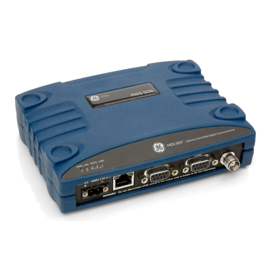
The MDS SD transceiver
(Figure
industrial radio for use in wireless telemetry applications. Models
offered at the time of printing include: MDS SD2 (215-235 MHz),
SD4 (350-512 MHz), and SD9 (928-960 MHz). The term SD is
used for information common to all models of the radio.
The radio supports both polled and report-by-exception data net-
works, and interfaces with a variety of data control equipment such
as remote terminal units (RTUs), programmable logic controllers
(PLCs), flow computers, and similar devices. Data interface con-
nections support both Ethernet and serial (RS-232/485) protocols.
LED INDICATOR
PANEL
CONNECTOR (RJ-45)
DC INPUT
POWER
SERIAL DATA
CONNECTORS (DB-9)
Figure 1. MDS SD Data Transceiver
1.1
About This Guide
This guide covers all SD transceivers except those operating in
x710 mode. A more detailed Technical Manual is also available
(05-4846A01). Before installing this product, refer to the Technical
Manual for important warnings, cautions, and notes. SD manuals
are available in printed or electronic form. All manuals are available
free of charge at www.gemds.com.
1.1.1
x710 Mode—Different Manuals Required
The radio may be configured to emulate a corresponding MDS
x710 transceiver. For x710 mode information, consult these man-
uals instead:
• Setup Guide (05-4669A01)
• Technical Manual (05-4670A01)
2.0
INSTALLATION
There are three main requirements for installing the transceiver:
• Adequate and stable primary power
• An efficient and properly installed antenna system
• Correct interface connections between the transceiver and
the data equipment.
Figure 2
shows a typical installation of the radio.
NOTE: Retrofit Kits are available to ease installation at former
MDS x710 digital and analog sites. Consult your factory
representative for ordering details.
2.1
Installation Steps
In most cases, the steps given here are sufficient to install the
transceiver. Refer to the Technical Manual for additional details, as
required.
05-4847A01, Rev. D
1) is a software-configurable,
ETHERNET
ANTENNA
Invisible
CONNECTOR (TNC)
place
holder
Invisible
place
holder
1. Mount the transceiver. Attach the supplied brackets to the
bottom of the transceiver case (if not already attached), using
the four 6-32 x 1/4 inch (6 mm) screws. Mounting bracket
dimensions are shown in
brackets are to be used, consult the Technical Manual for
instructions.
NOTE: To prevent moisture from entering the radio, do not mount
the case with the cable connectors pointing up. Also,
dress all cables to prevent moisture from running along
the cables and into the radio.
POWER SUPPLY
10.5–30 VDC @ 2.5A
Negative Ground Only
Figure 2. Typical Installation (Remote Site Shown)
Figure 3. Mounting Bracket Dimensions
2. Install the antenna and feedline. The antenna must be
designed to operate in the radio's frequency band, and be
mounted in a location providing a clear path to associated sta-
tion(s). At Remote sites, aim directional antennas toward the
Master Station. Low loss coaxial feedline should be used and
it should be kept as short as possible.
3. Connect the data equipment. Connection may be made
using Ethernet signaling, Serial protocols (RS-232/RS-485),
or both.
• If Ethernet is to be used, connect your data equipment to the
front panel Ethernet port next to the PWR connector.
MDS SD Series Setup Guide
MDS SD Series
Setup Guide
Figure
3. If DIN Rail mounting
ANTENNA SYSTEM
Master Stations typically use
omni-directional antenna
TRANSCEIVER
OR:
DATA TELEMETRY DEVICE
OR HOST COMPUTER
6.675˝ (16.95 cm)
1
Advertisement
Table of Contents

Related Manuals for GE MDS SD Series


Summary of Contents for GE MDS SD Series
- Page 1 Refer to the Technical Manual for additional details, as required. using Ethernet signaling, Serial protocols (RS-232/RS-485), or both. • If Ethernet is to be used, connect your data equipment to the front panel Ethernet port next to the PWR connector. 05-4847A01, Rev. D MDS SD Series Setup Guide...
- Page 2 The default entries for a new radio are both admin. Click OK. Figure 8. Overview Summary Screen NOTE: The radio may also be programmed using serial or Telnet management methods. Refer to the Technical Manual for details. MDS SD Series Setup Guide 05-4847A01, Rev. D...
- Page 3 NOTE: The radio’s RSSI facility limits the maximum displayed signal strength to -60 dBm. A receive signal attenuator is available in the Configuration>>Radio>>Advanced Settings screen. Figure 10. Spectrum Analyzer/Graph (Portion of Display) 05-4847A01, Rev. D MDS SD Series Setup Guide...
- Page 4 NOTE: The radio is hard-wired as a DCE device. GE MDS, LLC 175 Science Parkway Rochester, NY 14620 MDS SD Series Setup Guide General Business: +1 585 242-9600 05-4847A01, Rev. D FAX: +1 585 242-9620 July 2010 (Copyright 2010, GE MDS, LLC) Web: www.gemds.com...
Need help?
Do you have a question about the MDS SD Series and is the answer not in the manual?
Questions and answers