
Related Manuals for GE TransNET 900


Summary of Contents for GE TransNET 900
- Page 1 ™ MDS TransNET 900 ™ MDS TransNET 2400 Spread Spectrum Data Transceiver Including supplemental data for Board-Only units MDS 05-2708A01, Rev. F MARCH 2013...
- Page 2 Quick-Start instructions for this product are contained in publication 05-4481A01. All GE MDS manuals are available online at www.gemds.com...
-
Page 3: Table Of Contents
CONTENTS 1.0 ABOUT THIS MANUAL ..........1 2.0 PRODUCT DESCRIPTION ......... 1 2.1 Transceiver Features ............1 2.2 Model Number Codes .............2 2.3 Spread Spectrum Radios—How Are They Different? ..2 2.4 Typical Applications ............2 Multiple Address Systems (MAS) ........2 Point-to-Point System............3 Adding a Tail-End Link to an Existing Network ....3 Extending a TransNET Network with a Repeater....4 2.5 Accessories ..............5... - Page 4 5.1 Initial Start-up ..............19 5.2 Performance Optimization ..........20 Antenna Aiming..............20 Antenna SWR Check ............21 Data Buffer Setting—Modbus Protocol ......21 Hoptime Setting ..............21 TotalFlow™ Protocol at 9600 with Sleep Mode ....21 Operation at 115200 bps........... 21 Baud Rate Setting.............
- Page 5 CTSHOLD [0–60000] ............32 Clear-to-Send Hold Time DEVICE [DCE, CTS KEY] ..........32 Radio-MODEM Behavior DLINK [xxxxx/ON/OFF] .............32 InSite Diagnostics Link Support DKEY.................33 Turn Off Radio Transmitter‘s Test Signal DTYPE [NODE/ROOT]............33 Network Diagnostics Mode FEC [ON, OFF]..............33 Forward Error Correction HOPTIME [7, 28] ...............34 Radio Transmitter Hop Timing INIT..................34 Initialize;...
- Page 6 REPEAT [0–10]..............38 Downstream Repeat Transmission Count RETRY [0–10]..............38 Upstream Repeat Transmission Count RSSI.................. 38 Received Signal Strength Indicator RTU [ON, OFF, 0-80] ............39 Remote Terminal Unit Simulator RX [xxxx]................39 Radio Receive Test Frequency RXD [0–255] ..............39 RXD Delay RXTOT [NONE, 0–1440] ..........
- Page 7 XADDR [0–31] ..............44 Extended Address XMAP [00000000-FFFFFFFF] ..........44 Map of Extension Addresses XPRI [0–31] ...............44 Primary Extended Address XRSSI [NONE, –40...–120] ..........44 Extension RSSI Level ZONE CLEAR ..............44 Clear Zone Statistics Log ZONE DATA ..............44 Read Zone Statistics Log 7.0 TROUBLESHOOTING..........45 7.1 LED Indicators ..............46 7.2 Alarm Codes ..............46 Checking for Alarms—STAT command ......46...
- Page 8 10.7 dBm-Watts-Volts Conversion Chart ......76 Copyright Notice This manual and all software described herein are Copyright 2013 by GE MDS, LLC. All rights reserved, including the right to correct any errors and omissions in this manual. MDS TransNET Ref. Manual...
- Page 9 UL/CSA Notice The MDS TransNET 900 is available for use in Class I, Division 2, Groups A, B, C & D Haz- ardous Locations. Such locations are defined in Article 500 of the National Fire Protection Asso- ciation (NFPA) publication NFPA 70, otherwise known as the National Electrical Code.
- Page 10 The transceiver has been recognized for use in these hazardous locations by two independent agencies —Underwriters Laboratories (UL) and the Canadian Standards Association (CSA). The UL certification for the transceiver is as a Recognized Component for use in these hazardous locations, in accordance with UL Standard 1604, UL508.
- Page 11 Test Data Sheets showing the original factory test results for this unit are available upon request from the GE MDS Quality Leader. Contact the factory using the information at the back of this manual. Serial numbers must be provided for each product where a Test Data Sheet is required.
- Page 12 MDS TransNET Ref. Manual MDS 05-2708A01, Rev. F...
-
Page 13: About This Manual
1.0 ABOUT THIS MANUAL This manual presents installation and operating instructions of the MDS TransNET 900™ and MDS TransNET 2400™ transceivers for use by a professional installer. This person is expected to install, operate, and perform basic system maintenance on the described radio. Following instal- lation, we suggest keeping this manual near the equipment for future refer- ence. -
Page 14: Model Number Codes
• 2400–2482 MHz ISM band operation with the TransNET 2400 • User-selectable option to skip sub-bands with constant interference • 65,000 available network addresses • Network-wide configuration from the Master station eliminates most trips to Remote sites • Data transparency ensures compatibility with virtually all asynchronous SCADA system RTUs •... -
Page 15: Point-To-Point System
host computer and remote terminal units (RTUs) or other data collection devices. The operation of the radio system is transparent to the computer equipment. When used in this application, the transceiver provides an excel- lent alternative to traditional (licensed) MAS radio systems. Invisible place holder MDS TransNET Remote... -
Page 16: Extending A Transnet Network With A Repeater
TransNET radio links the outlying Remote site into the rest of a licensed MAS system by sending data from that site to an associated TransNET installed at one of the licensed Remote sites (see Figure As the data from the outlying site is received at the licensed Remote site, it is transferred to the licensed radio (via a local cable connection) and is then transmitted to the MAS Master station in the usual manner. -
Page 17: Accessories
2.5 Accessories The transceiver can be used with one or more of the accessories listed in Table 1. Contact the factory for ordering details. Table 1. Accessories Accessory Description Part No. AC Power Small power supply module designed for con- 01-3682A02 Adapter tinuous service. -
Page 18: Installation Planning
3.0 INSTALLATION PLANNING The installation of the radio is not difficult, but it does require some planning to ensure station reliability and efficiency. This section provides tips for selecting an appropriate site, choosing an antenna system, and reducing the chance of harmful interference. 3.1 General Requirements There are three main requirements for installing the radio—adequate and stable primary power, a good antenna system, and the compatible interface... -
Page 19: Terrain And Signal Strength
These requirements can be quickly determined in most cases. A possible exception is the last item—verifying that an unobstructed transmission path exists. Radio signals travel primarily by line-of-sight, and obstructions between the sending and receiving stations will affect system performance. If you are not familiar with the effects of terrain and other obstructions on radio transmission, the discussion below will provide helpful background. -
Page 20: A Word About Radio Interference
Factors such as terrain, distance, transmitter power, receiver sensitivity, and other conditions are taken into account to predict the perfor- mance of a proposed system. Contact the GE MDS Technical Services Group for more information on path study services. -
Page 21: Antenna & Feedline Selection
5. If constant interference is present in a particular frequency zone, it may be necessary to “lock out” that zone from the radio’s hopping pattern. The radio includes built-in tools to help users remove blocked frequency zones. Refer to the discussion of the command (Page 41) for more... -
Page 22: Feedlines
At Remote sites and point-to-point systems, a directional Yagi antenna (Figure 8), is generally recommended to minimize interference to and from other users. Antennas are available from a sources including GE MDS. Invisible place holder Figure 8. Typical Yagi Antenna... -
Page 23: Antenna System Ground
Table 2 lists several types of feedlines and indicates the signal losses (in dB) that result when using various lengths of each cable at 900 MHz and Table 3 for 2.4 GHz. The choice of cable will depend on the required length, cost considerations, and the amount of signal loss that can be tolerated. -
Page 24: How Much Output Power Can Be Used
Antenna Selection—Choose an antenna that offers a “DC ground” or direct low-impedance ground connection for all metallic components. This will allow static charges on the antenna system to be safely dissipated to ground. It will also provide a low-impedance discharge path to an earth/safety ground in the event of a direct lightning strike. - Page 25 For convenience, Table 4 lists several antenna system gains and shows the maximum allowable power setting of the radio. Note that a gain of 6 dB or less entitles you to operate the radio at full power output—30 dBm (1 watt). Table 4.
-
Page 26: Installation
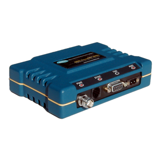
4.0 INSTALLATION Figure 9 shows the contents of a typical transceiver shipment. Check the contents against the packing list secured to the outside of the shipping box. Accessories and spare parts kits, if any, are wrapped separately. Inspect all items for signs of damage and save all packing materials for possible re-ship- ment. - Page 27 choose a mounting location that provides easy access to the connectors on the end of the radio and an unobstructed view of the LED status indicators. Invisible place holder 2.75 (7.0 cm) 6.63 (16.64 cm) 1.62 (4.15 cm) Figure 10. Transceiver Mounting Dimensions Figure 11 shows the four connectors on the transceiver and their functions.
- Page 28 Typical RS/EIA-232 applications require the use of Pin 2 (receive data—RXD and Pin 3 (transmit data—TXD). Some systems may require the use of Pin 7 (Request-to-send—RTS). Figure 13 shows connection details for DATA connector for EIA/RS-232 and EIA/RS-485, respectively. If hardware flow control is desired, Pin 7 (RTS) and Pin 8 (CTS) may also be connected.
- Page 29 The radio must be used only with negative-ground sys- CAUTION tems. Make sure the polarity of the power source is cor- rect. The unit is protected from reverse polarity by an POSSIBLE internal diode and fuse. EQUIPMENT DAMAGE Invisible place holder Lead Binding Screws (2)
-
Page 30: Configuring Multiple Remote Units
b. Set a unique Network Address (1–65000) using command. ADDR Each radio in the system must have the same network address. Tip: Use the last four digits of the Master’s serial number to help avoid conflicts with other users. Set the baud rate/data interface parameters. Default setting is 9600 bps, 8 data bits, no parity, 1 stop bit. -
Page 31: Configuring A Network For Extensions
DB-25 DB-9 If required. Figure 15. Data Interface Cable Wiring for Tail-End Links Any device on the left that requires a keyline, as in this illustration, will require the bottom line (CTS to RTS) and the TransNET on the right will need type set to . -
Page 32: Performance Optimization
• Remote radio(s) transmitting data ( ) and receiving data ( ) with Master station Table 6. LED indicator descriptions SYNC Name Description • Continuous—Power is applied to the radio; no problems detected • Flashing (5 times-per-second)—Fault indication “TROUBLESHOOTING” on Page 45 •... -
Page 33: Antenna Swr Check
Antenna SWR Check It is necessary to briefly key the transmitter for this check by placing the radio in the mode (Page 40) and using the command. (To unkey the SETUP radio, enter ; to disable the mode and return the radio to normal DKEY SETUP operation, enter... -
Page 34: Baud Rate Setting
Baud Rate Setting The default baud rate setting is 19200 bps to accommodate most systems. If your system will use a different data rate, you should change the radio’s data interface speed using the command (Page 29). It should be BAUD xxxxx abc set to the highest speed that can be sent by the data equipment in the system. -
Page 35: User Commands
The TransNET Configuration Software provides access to all of the radio’s capabilities with the benefit of context-sensitive help. The program is shipped as part of the TransNET support CD included with every order (CD P/N 03-2708A02) 6.2 User Commands A series of tables begin on the next page that provide reference charts of various user commands for the transceiver. - Page 36 Table 8. Network-Wide Diagnostics Command Description Controls operation of diagnostic link function. DLINK [xxxxx/ON/OFF] Details, Page 32 Set radio’s operational characteristics for DTYPE [NODE/ROOT] Details, network-wide diagnostics Page 33 Table 9. Operational Configuration—Set/Program Command Description Program network address ADDR [1–65000] Details, Page Alarm response AMASK [0000 0000–FFFF FFFF]...
- Page 37 Table 9. Operational Configuration—Set/Program (Continued) Command Description Owner’s name, or alternate message OWN [xxxxx] Details, Page 37 (30 characters maximum) Data port (DATA connector) interface PORT [RS232, RS485] Details, signaling mode: RS232 or RS485 Page 37 Power output in dBm PWR [20–30] Details, Page 38 (Figure 30 on Page...
- Page 38 Table 10. Operating Status—Display Only (Continued) Command Description Current sense of the alarm output. ASENSE Details Page 29 Data communication parameters. Example: BAUD BAUD 9600 8N1 Details Page 29 Data buffering mode: ON = seamless data, BUFF OFF = fast byte throughput Details Page 30 Security/encryption operational status.
- Page 39 Table 10. Operating Status—Display Only (Continued) Command Description The fixed downstream re-send count. REPEAT Details Page 38 The maximum upstream re-send count for RETRY ARQ (Automatic Repeat Request) operation. Details Page 38 Received signal strength indicator (in dBm). RSSI Unavailable at Master unless SETUP is Details Page 38 enabled.
-
Page 40: Detailed Command Descriptions
Table 10. Operating Status—Display Only (Continued) Command Description Address of the primary Extended radio unit XPRI (Extension). Details Page 44 Included Extended units in MODE X. XMAP (Extensions and Remotes only). Details Page 44 Minimum RSSI level required to preserve XRSSI synchronization with a non-primary radio. -
Page 41: Addr [1-65000]
ADDR [1–65000] Network Address This command sets or displays the radio’s network address. The network address can range from 1 to 65000. A network address must be programmed at the time of installation and must be common across each radio in a given network. Radios are typically shipped with the network address unprogrammed, causing the address to display as . -
Page 42: Data Interface Port Baud Rate
The first parameter ( ) is baud rate. Baud rate is specified in xxxxx bits-per-second and must be one of the following speeds: 300, 600, 1200, 1800, 2400, 4800, 9600, 19200, 38400, 57600, or 115200. At baud rates of 19200 bps or less, the radio can support unlimited continuous data transmis- sion at any hop rate. -
Page 43: Data Buffer Mode
Seamless mode ( ) is intended only for applications where the BUFF ON message size is 256 characters or less. Enforcement of this rule is left up to the user. If more than 256 characters are transmitted data delivery will not be seamless and data may be lost. -
Page 44: Ctshold [0-60000]
For CTS Key operation (see the command), the timer specifies how DEVICE DATA long to wait after asserting the CTS line before sending data out the port. A timer value of zero means that data will be sent out the data port without imposing a key-up delay. -
Page 45: Insite Diagnostics Link Support
The following baud rates selections are supported: DLINK • 1200 • 4800 • 9600 • 19200 (default) • 38400 • 57600 • 115200 DIAG Example: sets the RJ-11 port to operate at 4800 bps when DLINK 4800 diagnostics is closed. This setting will not affect the port’s autobaud opera- tion. -
Page 46: Hoptime [7, 28]
HOPTIME [7, 28] Radio Transmitter Hop Timing command is used to set or display the hop-time setting. The HOPTIME command is a digit corresponding to the hop-time setting in milliseconds. The default setting is . A setting of must be used when throughputs HOPTIME exceed 57,600 bps and is recommended when data transmission sizes exceed 256 bytes. -
Page 47: Hrev
Table 12. INIT Command Generated Defaults (Continued) Corresponding Parameter Default Setting Command LED Operation Low-Power Mode LPMHOLD Hold None/Disable RX Time-Out-Timer RXTOT 30 dBm (1 watt) RF Output Power PWR 30 915.000 MHz or Transmitter TX xxx 2436.0 MHz Test Frequency (Model dependent) 915.000 MHz Receiver... -
Page 48: Led [On, Off]
LED [ON, OFF] Enable/Disable PCB LEDs enables/disables the PCB board mounted LEDs seen only with the LED ON transceiver’s covers removed. is normally , it may be useful to have them on for testing the radio with the covers removed. Note: the external LEDs will be dimmer if the function is left command also affects the operation of the LEDs in the “Low-Power... -
Page 49: Radio Operating Mode
All units default to Remotes; other modes must be specifically programmed with the command. MODE is used, the radio should be programmed with an MODE X MODE X Extended Address ( ). Units that need to hear this radio must XADDR MODE X be programmed with an appropriate... -
Page 50: Pwr [20-30]
pass. Pin descriptions for EIA-232 are on page 69 and EIA-485 can be found page PWR [20–30] Radio Transmitter Power Level This command displays or sets the desired RF power output of the radio. The command parameter is specified in dBm and can be adjusted in 1 dBm steps. - Page 51 Remote Terminal Unit Simulator This command re-enables or disables the radio’s internal RTU simulator, which runs with GE MDS proprietary polling programs (poll.exe and rsim.exe). The internal RTU simulator is available whenever a radio has diag- nostics enabled. This command also sets the RTU address to which the radio will respond.
- Page 52 Entering a (0 ms default) or will enable the function. RXD ON RXD XX Entering will disable the function and erase any stored value. RXD OFF RXTOT [NONE, 0–1440] Receive Data Timeout-Timer This command sets or displays the amount of time (in minutes) to wait for the next received data packet before issuing a receiver time-out alarm.
- Page 53 SHOW CON Show Virtual Connection Status Shows virtual connection status established by the latest ATDT command sequence. (Works only with See“AT [ON, OFF]” on Page AT ON If no connection is established, it displays NONE If a connection is active, it will display: <Master unit address>...
- Page 54 In the USA, a maximum of four zones may be skipped for TransNET 900 and a maximum of three zones may skipped for TransNET 2400. Check the regu- latory requirements for your region. The function may not be permitted SKIP in your country and the radio will not respond to the command.
- Page 55 A display of is an example of the firmware version identi- 06-4040A01, 3.6.1 fier—part number followed by release/version number. STAT Alarm Status This command is used to check the alarm status of the radio. If no alarms exist, the message is returned.
-
Page 56: Xaddr [0-31]
XADDR [0–31] Extended Address Used to display or program the Extended Address of this radio that will serve as a common address for the sub-network synchronized to this Master or Extension. This value can be listed in the parameter of associated Exten- XPRI sion or Remote radios to allow them to synchronize to this radio. -
Page 57: Troubleshooting
Historical information on the quality of each zone can be accessed using the command. The report shows you the number of data frames sent, ZONE DATA the number received, and the number received with errors. If an excessive number of errors are seen in one or more frequency zones, it may indicate interference, and you should consider “skipping”... -
Page 58: Led Indicators
• Check for errors in the synchronization qualifiers, XPRI XMAP on corresponding Remote radios. • Verify is enabled at the Master radio. 7.1 LED Indicators The LED status indicators are an important troubleshooting tool and should be checked whenever a problem is suspected. Table 17 describes the function of each status LED. -
Page 59: Alarm Code Definitions
With the exception of alarm code 00 (network address not programmed), major alarms generally indicate the need for factory repair. Contact the factory for further assistance. Minor alarms report conditions which, under most circumstances, will not prevent transceiver operation. This includes out-of-tolerance conditions, baud rate mismatches, etc. -
Page 60: Troubleshooting Chart
7.3 Troubleshooting Chart Table 19 provides suggestions for resolving system difficulties that may be experienced in the radio system. If problems persist, contact the factory for further assistance. Refer to the inside back cover of this guide for contact information. Table 19. -
Page 61: Performing Network-Wide Remote Diagnostics
7.4 Performing Network-Wide Remote Diagnostics Diagnostics data from a Remote radio can be obtained by connecting a laptop or personal computer running MDS InSite diagnostics software (Version 6.6 or later) to any radio in the network. NOTE: The diagnostics feature may not be available in all radios. The ability to query and configure a radio via Network-wide Diagnostics is based on the feature op- tions purchased in the radio being polled. -
Page 62: Internal Fuse Replacement
7.5 Internal Fuse Replacement The radio is protected by an internal fuse. This fuse can be blown by an over-voltage transient or an internal failure. Follow the procedure below to remove and replace the fuse: 1. Disconnect the primary power cable and all other connections to the unit. 2. -
Page 63: Radio Firmware Upgrades
8.0 RADIO FIRMWARE UPGRADES From time to time, the factory releases new firmware for its radio products. This file can be installed in existing radios to take advantage of engineering improvements or additional features. 8.1 Obtaining New Firmware The latest firmware for each radio type may be obtained free from our Web site at: www.gemds.com Firmware is also available on disks from the factory that are bundled with an... -
Page 64: Operating Principles And Configuration
9.0 OPERATING PRINCIPLES AND CONFIGURATION 9.1 SAF Operation with Extension Radios The Store-and-Forward (SAF) capability operates by dividing a network into a vertical hierarchy of two or more sub-networks. (See Figure 5 on Page Adjacent sub-networks are connected via Extension radios operating in “... -
Page 65: Extended Saf Network
Extended SAF Network Below is an example of a multilevel network utilizing two repeaters—X and X . The example demonstrates the extensibility of the network. In this case, messages directed to Remotes in the sub-network L will be relayed through Extension radios X and X . -
Page 66: Synchronizing Network Units
Mode X and M Radios—Can have direct reports (Mode R radios) out- side of the chain. Data (Payload)—Travels from Master to Remote, and back from Remote to Master. Mode X and R Radios—Extension links can be protected by mapping one or more fall-back paths in case of a failure. Add secondary exten- sion addresses (XADDR) into the table. -
Page 67: Synchronization Messages
All Remotes synchronize to a corresponding Master. This can be the “real Master” (the unit), or it can be a repeater “Extension” that derives MODE M synchronization from the “real Master.” Payload polls/packets broadcast from the network Master will be repeated to all levels of the network, either directly to Remotes, or through network repeaters—the Extension station. - Page 68 connections where wire lines were the only communications link available at the time. Most of these older system implemented support for the AT commands needed in the host software, so TransNET units can be used without software modifications. DATA In this mode, the Master’s port is parsed for a subset of AT commands.
-
Page 69: Configuration Parameters For S&F Services
AT <command errors> Replies with (Code 4) ERROR Characters with <no AT command> Modem will echo characters in data stream but will be ignored until a second “AT” is seen at which time the modem closes the virtual connection. Operation Notes When AT Commands are ON •... - Page 70 Table 21. Configuration Parameters for SAF Services Network Master Radio (Continued) Parameter Command Description A number between 0 and Extended Address XADDR 31 that will serve as a Details Page 44 common address for radi- os that synchronize di- rectly to this Master. Typically, the Master is set to zero (0).
-
Page 71: Using The Radio's Sleep Mode (Remote Units Only)
Table 23. Configuration Parameters for SAF Services Remote Radio(s) Parameter Command Description Sets the radio to serve Operating Mode MODE R as a Remote station. Details Page 36 A number between 1 Network Address ADDR and 65,000 that will Details Page 29 serve as a common network address or name. -
Page 72: Sleep Mode Example
It is important to note that power consumption will increase somewhat as communication from the Master station degrades. This is because the radio will spend a greater period of time “awake” looking for synchronization messages from the Master radio. In order for the radio to be controlled by Pin 4, the unit’s Sleep Mode must be enabled through the command. -
Page 73: Reading Rssi & Other Parameters W/Lpm Enabled
Reading RSSI and Other Parameters with LPM Enabled It may be desired to perform tests and review operational settings of a Remote radio which has been programmed to operate in the low-power mode. Follow the abbreviated procedure below to interact with the radio through a local computer. -
Page 74: Low-Power Mode Versus Remote's Sleep Mode
9.7 Low-Power Mode versus Remote’s Sleep Mode The Low-Power Mode (LPM) puts Remote radios into an operational config- uration similar to Sleep, but there are some important differences. Below is a comparison of the two modes. Table 25. Power-Conservation Modes Comparison Sleep Mode Low-Power Mode •... -
Page 75: Operational Influences-Hoptime & Saf
Operational Influences—Hoptime & SAF The synchronization period is influenced by two parameters’ values— HOPTIME (Store-and-Forward). Table 26 shows several configurations and the associated synchronization period value. Table 26. Synchronization Period versus Hoptime and SAF Settings Sync Period Hoptime Value 441 ms 1.8 sec 3.5 sec 9.9 MIRRORED BITS™... -
Page 76: Master Station Configuration
in order to reduce the interference to the point where overload of one network by the other will not occur. The command will provide relief from CSADDR this antenna separation requirement by operating the networks in a TDD mode and ensuring that one Master cannot transmit while the other (or multiple others) are trying to receive a signal from a distant radio. -
Page 77: Security
An accompanying concern becomes the security of the communication infrastructure and the security of the data itself. GE MDS takes this matter seriously, and provides several means for protecting the data carried over its wireless products. -
Page 78: Technical Reference
The items described above provide sufficient security for a typical MAS system. For more highly-sensitive applications, system designers should consider employing application level encryption into their polling protocols to further protect their systems. Third party software tools are available for adding encryption, and these should be considered as part of any advanced encryption scheme. -
Page 79: Product Specifications-2.4 Ghz
Data Rate: 300, 600, 1200, 1800, 2400, 4800, 9600, 19200, 38400, 57600, 115200 bps asyn- chronous Data Latency: 7 ms typical Byte Length: 10 or 11 bits Maximum Data Transmission: Continuous up to 115200 bps RF CHARACTERISTICS (TNC RF Connector) TRANSMITTER: Power Output (at antenna connector):... - Page 80 Primary Power: 13.8 Vdc, Nominal (6–30 Vdc range) Current Draw (typical @ 27 dBm): Transmit: 510 mA @ 13.8 Vdc Receive: 100 mA @ 13.8 Vdc 3 mA @ 13.8 Vdc Sleep Mode (typical): Size: 5.30˝ W x 3.50˝ D x 1.40˝H (135 W x 89 D x 36 H mm).
-
Page 81: Diagnostic Interface Connections (Rj-11)
10.3 Diagnostic Interface Connections (RJ-11) Invisible place holder RJ-11 PLUG DB-9 FEMALE (TO RADIO) (TO COMPUTER) RJ-11 PIN LAYOUT Figure 21. RJ-11 to DB-9 Adapter Cable—Wiring Details NOTE: Only wire pins 4, 5, and 6. Pins 1,2, and 3 are reserved for special functions and are not normally connected. -
Page 82: Pin Descriptions-Rs/Eia-232 Mode
Pin Descriptions—RS/EIA-232 Mode DATA Table 27 lists the connector pin functions for radios configured to operate in RS/EIA-232 mode. NOTE: The radio is hard-wired as a DCE in the EIA-232 mode. Table 27. DATA connector pin descriptions—RS/EIA-232 Input/ Number Output Pin Description DCD (Data Carrier Detect) A “high”... -
Page 83: Pin Descriptions-Rs/Eia-422/485 Mode
Pin Descriptions—RS/EIA-422/485 Mode DATA Table 28 lists the connector pin functions for radios configured to operate in RS/EIA-422/485 mode. See Figure 23 for wiring schemes. Table 28. DATA connector pin descriptions—RS-422/485 Mode Input/ Number Output Pin Description — Not Used—Do not connect TXD+/TXA—Non-inverting driver output. -
Page 84: Board-Only Supplemental Data
10.5 Board-Only Supplemental Data The TransNET 900 board-only radio is electrically and operationally similar to the standard (metal enclosed) version described in the body of this manual. Refer to this manual for connector assignments, software commands and other product information. This supplementary data explains the items that are unique to the board-only radio. -
Page 85: Mounting Requirements
Network-Wide Diagnostics Protocol. Specifications for this protocol are open and are contained within the InSite distribution material on CD and on the GE MDS Web site. One pin of the DB-9 Data Interface connector supports this function, as well as three pins of the RJ-11 Diagnostics connector. See Tables on the previous pages for details. - Page 86 Care should be taken when soldering to the PCB eyelets due to their small size. For this reason, only qualified personnel should CAUTION install the jumpers and external connections. Installation of internal jumpers and connection to non-standard POTENTIAL interface pins may void the product’s warranty. EQUIPMENT If you are uncertain of your interface design, please consult with DAMAGE...
-
Page 87: Using The I/O Points With Insite™ Nms Software
Table 29. TransNET User I/O Connection Resources Available Data Interface Pin at eyelet: DB-9, Pin 9 RJ-11, Pin 1 RJ-11, Pin 2 RJ-11, Pin 3 a. Configuration and data retrievable via MDS InSite™ software as “I/O 1” b. Configuration and data retrievable via MDS InSite™ software as “I/O 2” c. -
Page 88: Dbm-Watts-Volts Conversion Chart
10.7 dBm-Watts-Volts Conversion Chart Table 30 is provided as a convenience for determining the equivalent voltage or wattage of an RF power expressed in dBm with 50 Ohms load. Table 30. dBm-Watts-Volts Conversion Chart dBm V dBm V dBm mV dBm µV 100.0 200W .225... - Page 89 INDEX Accessories (table) 5 ADDR command (set/display radio network address) 29 Alarm checking for 46 code definitions 47 codes 46 codes, table 47 major vs. minor 46 receiver timeout (RXTOT command) 40 reset output signal 29 set/display output sense (ASENSE command) 29 status (STAT command) 43 ALARM command (superseded;...
- Page 90 ADDR (set/display radio network address) 29 AMASK (configure alarm output signal) 29 ASENSE (set/display alarm output sense) 29 BAUD (set/display data interface port attributes) 29 BUFF (set/display received data handling mode) 30 CODE (set/display encryption value), See also Encryption 31 CTS (set/display CTS line response timer) 31 CTSHOLD (set/display CTS hold timer) 32 detailed descriptions 28–44...
- Page 91 XPRI (display/program primary radio’s extended address) 44 XRSSI (sets min. signal level for sync. with non-primary extension unit) 44 Connectors Diagnostic Interface, Connections 69 Data Baud Rate (BAUD) Command 29 Data Baud Rate (BUFF) Command 30 Data buffer setting 21, 30 DATA INTERFACE cable wiring for tail-end links, illustrated 19 connections 69...
- Page 92 Downstream Repeat Transmission Count (REPEAT) Command 38 DSP (digital signal processing) 1, 47 DTYPE command (set radio’s diagnostics type) 33, 49, 50 Enable internal RTU (RTU command) 39 network-wide diagnostics, procedures 49 Setup mode (SETUP command) 40 skipped zone (SKIP command) 41 Sleep Mode Enable/Disable LEDs (LED) Command 36 Encryption.
- Page 93 feedline selection 10 performance optimization 20 requirements 6 site selection 6 site survey 7 tail-end links 18 transmission path 7 Interference about 8 checks 22 troubleshooting 48 interference 8 set to CTS keying (DEVICE command) 32 transmitter, for antenna SWR check 21 KEY command (key transmitter) 21, 40 LED status indicators table 20, 46...
- Page 94 procedures 49 Node (radio diagnostics type) 33, 50 LED 36 Modbus, BUFF 30 Operation 19–22 OWM command (set/display optional owner’s message) 37 OWN command (set/display optional owner’s name) 37 Owner’s Message (OWM) Command 37 Owner’s Name Command (OWN) 37 connecting to radio’s diagnostic port 49 launching InSite application at 49 performing diagnostics using connected 49 Peer (radio diagnostics type) 33, 50...
- Page 95 Programming radio 28–44 as root or node 49 PWR command (set/display RF forward output power) 38 Radio inoperative (troubleshooting chart) 48 no synchronization with master (troubleshooting chart) 48 poor performance (troubleshooting chart) 48 Radio Operating Mode (MODE) Command 36, 37 Radio Receive Test Frequency Command (RX) 39 Radio Serial Number Command (SER) 40 Radio Transmit Test Frequency (TX) 43...
- Page 96 DCE or CTS Key device behavior (DEVICE command) 32 frequency zone to skip (SKIP command) 41 hoptime (HOPTIME command) 34 network address (ADDR command) 29 owner’s message (OWM command) 37 owner’s name (OWN command) 37 radio mode (see MODE command) 36 received data handling mode (BUFF command) 30 received data timeout value (RXTOT command) 40 receiver test frequency (RX command) 39...
- Page 97 Temperature, display internal (TEMP command) 43 Terrain 7 Terrain and Signal Strength 7 Test, on-the-air 7 Transceiver connecting to data equipment 15, 22 default settings 34 mounting instructions/dimensions 14–15 performance optimization 20 sleep mode 59 Transceiver Sleep (SLEEP) 42 Troubleshooting 45–48 performing network-wide diagnostics 49 table 48 Turn Off Radio Transmitter Test Signal (DKEY) Command 33...
- Page 98 I-10 MDS TransNET Ref. Manual MDS 05-2708A01, Rev. F...
- Page 99 IN CASE OF DIFFICULTY... GE MDS products are designed for long life and trouble-free operation. However, this equipment, as with all electronic equipment, may have an occa- sional component failure. The following information will assist you in the event that servicing becomes necessary.
- Page 100 GE MDS, LLC 175 Science Parkway Rochester, NY 14620 General Business: +1 585 242-9600 FAX: +1 585 242-9620 Web: www.gemds.com...
Need help?
Do you have a question about the TransNET 900 and is the answer not in the manual?
Questions and answers