Motorola MVME2700 Series Installation And Use Manual
Mvme2700 series single board computer
Hide thumbs
Also See for MVME2700 Series:
- Reference manual (283 pages) ,
- Installation and use manual (215 pages)
Table of Contents
Advertisement
Quick Links
Advertisement
Table of Contents

Related Manuals for Motorola MVME2700 Series


Summary of Contents for Motorola MVME2700 Series
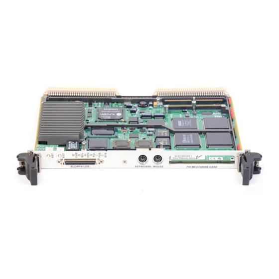
- Page 1 MVME2700 Series Single Board Computer Installation and Use V2700A/IH2 August 2000...
- Page 2 While reasonable efforts have been made to assure the accuracy of this document, Motorola, Inc. assumes no liability resulting from any omissions in this document, or from the use of the information obtained therein. Motorola reserves the right to revise this document and to make changes from time to time in the content hereof without obligation of Motorola to notify any person of such revision or changes.
- Page 3 Preface The MVME2700 Series Single Board Computer Installation and Use manual provides general information, hardware preparation and installation instructions, operating instructions, a functional description, and various types of interfacing information for the MVME2700 family of single-board computers.The information in this manual applies to MVME2700 models assembled from any of the plug-together components listed in the following list.
-
Page 4: Ground The Instrument
The safety precautions listed below represent warnings of certain dangers of which Motorola is aware. You, as the user of the product, should follow these warnings and all other safety precautions necessary for the safe operation of the equipment in your operating environment. - Page 5 Vorsicht Hersteller empfohlenen Typ. Entsorgung gebrauchter Batterien nach Angaben des Herstellers. All Motorola PWBs (printed wiring boards) are manufactured by UL-recognized manufacturers, with a flammability rating of 94V-0. This equipment generates, uses, and can radiate electro- magnetic energy. It may cause or be susceptible to electro-...
- Page 6 Motorola symbol are registered trademarks of Motorola, Inc. AIX™ is a trademark of IBM Corp. ® PowerPC is a registered trademark of IBM Corp. and is used by Motorola with permission. All other products mentioned in this document are trademarks or registered trademarks of their respective holders.
-
Page 7: Table Of Contents
Contents CHAPTER 1 Introduction to the MVME2700 Overview ........................1-1 Equipment Required ....................1-3 Overview of Startup Procedure ..................1-5 Unpacking Instructions ....................1-6 Hardware Configuration.....................1-6 CHAPTER 2 Hardware Preparation Overview ........................2-1 MVME2700 Base Board Preparation ................2-2 MVME712M Transition Module Preparation ............2-8 MVME761 Transition Module Preparation .............2-18 Three-Row Adapter ...................2-39 Five-Row Adapter ..................2-39 CHAPTER 3... - Page 8 Programming Considerations ..................4-7 Processor/Memory Domain ..............4-11 PCI Domain....................4-12 VMEbus Domain ..................4-13 CHAPTER 5 Functional Description Overview........................5-1 Features........................5-1 General Description ....................5-3 Block Diagram......................5-5 SCSI Termination..................5-7 Asynchronous Serial Ports ................ 5-10 Parallel Port ....................5-10 Disk Drive Controller................
- Page 9 APPENDIX A Related Documentation Motorola Computer Group Documents ..............A-1 Manufacturers’ Documents..................A-2 Related Specifications....................A-6 APPENDIX B Specifications MVME2700 Board Specifications................B-1 Cooling Requirements ....................B-2 EMC Compliance...................... B-3 APPENDIX C Serial Interconnections Introduction....................... C-1 EIA-232-D Connections ................... C-2 EIA-530 Connections....................C-5 Proper Grounding......................
- Page 10 List of Tables Table 1-1. VMEmodule/Transition Module Correspondence........1-3 Table 1-2. Startup Overview ..................1-5 Table 2-1. Jumper Settings..................2-2 Table 2-2. MVME712M Port/Jumper Correspondence ...........2-10 Table 4-1. MVME2700 LEDs..................4-3 Table 4-2. Processor Default View of the Memory Map ...........4-5 Table 4-3. PCI Arbitration Assignments..............4-8 Table 4-4.
- Page 11 Table 6-20. Ethernet 10Base-T/100Base-TX Connector (MVME761)....6-25 Table 7-1. Debugger Commands ................7-4 Table 7-2. Diagnostic Test Groups ................7-8 Table A-1. Motorola Computer Group Documents ..........A-1 Table A-2. Manufacturers’ Documents ..............A-2 Table A-3. Related Specifications ................A-6 Table B-1.
- Page 12 List of Figures Figure 1-1. MVME2700 Base Board Block Diagram ..........1-2 Figure 2-1. MVME2700 Switches, Headers, Connectors, Fuses, LEDs ....2-3 Figure 2-2. MVME712M Connector and Header Locations ........2-9 Figure 2-3. J15 Clock Line Configuration ...............2-10 Figure 2-4. MVME712M Serial Port 1 DCE/DTE Configuration......2-11 Figure 2-5.
- Page 13 Figure 3-4. MVME712M/MVME2700 Cable Connections........3-13 Figure 3-5. MVME761/MVME2700 Cable Connections ........3-15 Figure 4-1. PPCBug Firmware System Startup............4-2 Figure 4-2. VMEbus Master Mapping............... 4-7 Figure 4-3. MVME2700 Interrupt Architecture ............4-9 Figure 5-1. MVME2700 Block Diagram ..............5-5...
- Page 14 1Introduction to the MVME2700 Overview This manual provides general information, hardware preparation and installation instructions, operating instructions, and a functional description of the MVME2700 family of single-board computers. ® The MVME2700 is a single-slot VMEmodule equipped with a PowerPC 750 microprocessor. 32KB L1 cache (Level 1 cache memory) and 1MB L2 cache (Level 2 ‘‘backside’’...
-
Page 15: Chapter 1 Introduction To The Mvme2700
Introduction to the MVME2700 CLOCK DEBUG CONNECTOR MEMORY EXPANSION CONNECTORS GENERATOR L2 CACHE FLASH FLASH 4MB or 8MB SYSTEM PROCESSOR MPC750 REGISTERS PHB & MPIC MEMORY CONTROLLER RAVEN ASIC FALCON CHIPSET 33MHz 32/64-BIT PCI LOCAL BUS ETHERNET SCSI VME BRIDGE W83C553 DEC21140 53C825A... -
Page 16: Equipment Required
Equipment Required Equipment Required The following equipment is required to complete an MVME2700 system: VME system enclosure System console terminal Operating system (and/or application software) Disk drives (and/or other I/O) and controllers Transition module (MVME712M or MVME761) and connecting cables MVME2700 VMEmodules are factory-configured for I/O handling via either MVME712M or MVME761 transition modules. - Page 17 *All models have 233MHz, 266MHz or 366MHz processors, 5MB or 8MB Flash memory and 1MB L2 cache. In models of the MVME2700 series that are configured for MVME712M I/O mode, the pin assignments of VMEbus connector P2 are fully compatible with other transition modules of the MVME712 series. In MVME761-compatible models, certain signals are multiplexed through P2 for additional I/O capacity.
-
Page 18: Overview Of Startup Procedure
Overview of Startup Procedure Overview of Startup Procedure The following table lists the things you will need to do before you can use this board and tells where to find the information you need to perform each step. Be sure to read this entire chapter, including all Caution and Warning notes, before you begin. -
Page 19: Unpacking Instructions
Introduction to the MVME2700 Unpacking Instructions Note If the shipping carton is damaged upon receipt, request that the carrier’s agent be present during the unpacking and inspection of the equipment. Unpack the equipment from the shipping carton. Refer to the packing list and verify that all items are present. - Page 20 2Hardware Preparation Overview The following sections discuss the: Preparation of the MVME2700 base board, including jumper settings Preparation of the MVME712M and MVME761transition modules Preparation of the P2 adapter card Covered in this chapter is information on the configurable items on the MVME2700 base board and MVME712M and MVME761 transition modules and their serial port settings and configurations.
-
Page 21: Chapter 2 Hardware Preparation
Hardware Preparation MVME2700 Base Board Preparation Figure 2-1 illustrates the placement of the switches, jumper headers, connectors, and LED indicators on the MVME2700. Manually configurable items on the base board are listed in the following table. Refer to the sections or figures listed along side the jumper function for more information. -
Page 22: Figure 2-1. Mvme2700 Switches, Headers, Connectors, Fuses, Leds
MVME2700 Base Board Preparation C HS C PU PC I J8 and J10 connectors are unpopulated 11865.00 9709 Figure 2-1. MVME2700 Switches, Headers, Connectors, Fuses, LEDs http://www.mcg.mot.com/literature... - Page 23 Hardware Preparation Flash Bank Selection (J9) The MVME2700 base board has provision for 1MB of 16-bit Flash memory. The RAM200 memory mezzanine accommodates 4MB or 8MB of additional 64-bit Flash memory. The Flash memory is organized in either one or two banks, each bank either 16 or 64 bits wide.
- Page 24 MVME2700 Base Board Preparation Serial port configurations for the MVME712M are illustrated in figures through 2-9. Serial port configurations for the MVME761 are illustrated in figures 2-11 through 2-28. Serial Port 4 Transmit Clock Configuration (J17) In synchronous serial communications, you can configure serial port 4 on the MVME2700 to use the clock signals provided by the TxC signal line.
- Page 25 Hardware Preparation As described in other sections, a complete configuration of serial port 4 requires that you set additional jumper headers on the MVME2700 or the transition module. Buffer Enabled Buffer Disabled (factory configuration) Serial port configurations for the MVME712M are illustrated in figures through 2-9.
- Page 26 MVME2700 Base Board Preparation System Controller Selection (J20) The MVME2700 is factory-configured as a VMEbus system controller by jumper header J20. If you select the “automatic” system controller function by placing a jumper on J20 pins 2 and 3, the MVME2700 determines whether it is the system controller by its position on the bus.
-
Page 27: Mvme712M Transition Module Preparation
Hardware Preparation MVME712M Transition Module Preparation The MVME712M transition module and P2 adapter board are used in conjunction with the following models of the MVME2700 VMEmodule: With MCG front panel/handles With Scanbe front panel/handles MVME2700-4321 (16MB ECC DRAM) MVME2700-4221A (16MB ECC DRAM) MVME2700-4331 (32MB ECC DRAM) MVME2700-4231A (32MB ECC DRAM) MVME2700-4341 (64MB ECC DRAM) -
Page 28: Figure 2-2. Mvme712M Connector And Header Locations
MVME712M Transition Module Preparation M VM E712M Figure 2-2. MVME712M Connector and Header Locations http://www.mcg.mot.com/literature... -
Page 29: Table 2-2. Mvme712M Port/Jumper Correspondence
Hardware Preparation Serial Ports 1-4 DCE/DTE Configuration Serial ports 1 through 4 are configurable as modems (DCE) for connection to terminals, or as terminals (DTE) for connection to modems. The MVME712M is shipped with the serial ports configured for DTE operation. -
Page 30: Figure 2-4. Mvme712M Serial Port 1 Dce/Dte Configuration
MVME712M Transition Module Preparation MVME2700 SERIES P2 ADAPTER 64-PIN MVME712M VME MODULE BOARD CABLE MODULE PC87308 SOUT1 RTS1# DTR1# +12V SIN1 DB25 CONNECTOR CTS1# DCD1# +12V DSR1# RI1# Install all jumpers on J1 Remove all jumpers on J11 11551.00 9609 (1-8) 11551.00 9609 (2-8) -
Page 31: Figure 2-5. Mvme712M Serial Port 2 Dce/Dte Configuration
Hardware Preparation MVME2700 SERIES P2 ADAPTER 64-PIN MVME712M VME MODULE BOARD CABLE MODULE PC87308 SOUT2 RTS2# DTR2# DB25 SIN2 CONNECTOR CTS2# DCD2# DSR2# +12V RI2# Install all jumpers on J16 Remove all jumpers on J17 11551.00 9609 (3-8) 11551.00 9609 (4-8) -
Page 32: Figure 2-6. Mvme712M Serial Port 3 Dce Configuration
MVME712M Transition Module Preparation MVME2700 SERIES 64-PIN MVME712M VME MODULE ADAPTER CABLE MODULE Z85230 TXDA RTSA# DCDA# RXDA CTSA# TRXCA# DB25 RTXCA# CONNECTOR Z8536 DTR3# LLB3# RLB3# DSR3# +12V RI3# TM3# Install all jumpers on J13 Header J18 is open Remove all jumpers on J14 11551.00 9609 (5-8) -
Page 33: Figure 2-7. Mvme712M Serial Port 3 Dte Configuration
Hardware Preparation MVME2700 SERIES 64-PIN MVME712M VME MODULE ADAPTER CABLE MODULE Z85230 TXDA RTSA# DCDA# RXDA CTSA# TRXCA# DB25 RTXCA# CONNECTOR Z8536 DTR3# LLB3# RLB3# DSR3# RI3# TM3# Install all jumpers on J14 Header J18 is open Remove all jumpers on J13 11551.00 9609 (6-8) -
Page 34: Figure 2-8. Mvme712M Serial Port 4 Dce Configuration
MVME712M Transition Module Preparation 64-PIN MVME712M MVME2700 SERIES VME MODULE ADAPTER CABLE MODULE Z85230 TXDB RTSB# DCDB# RXDB CTSB# TXCI RXCI TXCO TRXCB RTXCB DB25 CONNECTOR Z8536 DTR4# LLB4# RLB4# DSR4# RI4# TM4# Install all jumpers on J18 Headers: J16 2-3... -
Page 35: Figure 2-9. Mvme712M Serial Port 4 Dte Configuration
Hardware Preparation 64-PIN MVME712M MVME2700 SERIES ADAPTER CABLE MODULE VME MODULE Z85230 TXDB RTSB# DCDB# RXDB CTSB# TXCI RXCI TXCO TRXCB RTXCB DB25 CONNECTOR Z8536 DTR4# LLB4# RLB4# DSR4# RI4# TM4# Install all jumpers on J19 Headers: J16 2-3 Remove all jumpers on J18... -
Page 36: Figure 2-10. Mvme712M Three-Row P2 Adapter
In its factory configuration, the MVME712M transition module uses a three-row P2 adapter to transfer synchronous/asynchronous serial, parallel, and Ethernet signals to and from the MVME2700 series VMEmodule. A 50-pin male connector (J3) on the P2 adapter carries 8-bit SCSI signals from the MVME2700. -
Page 37: Mvme761 Transition Module Preparation
Hardware Preparation MVME761 Transition Module Preparation The MVME761 transition module (Figure 2-11) and P2 adapter board are used in conjunction with the following models of the MVME2700 VMEmodule: MCG front panel/handles Scanbe front panel handles MVME2700-1221A (16MB ECC DRAM) MVME2700-3221A (16MB ECC DRAM) MVME2700-1231A (32MB ECC DRAM) MVME2700-3231A (32MB ECC DRAM) MVME2700-1241A (64MB ECC DRAM) -
Page 38: Figure 2-11. Mvme761 Connector And Header Locations
MVME761 Transition Module Preparation MVME 761-001 Figure 2-11. MVME761 Connector and Header Locations http://www.mcg.mot.com/literature 2-19... -
Page 39: Serial Ports 1 And 2
Hardware Preparation Serial Ports 1 and 2 On MVME761-compatible models of the MVME2700, the asynchronous serial ports (serial ports 1 and 2) are configured permanently as Data Circuit-terminating Equipment (DCE). The port configuration is illustrated in Figure 2-12. Configuration of Serial Ports 3 and 4 The synchronous serial ports, serial port 3 and serial port 4, are configurable through a combination of serial interface module (SIM) selection and jumper settings. - Page 40 MVME761 Transition Module Preparation Headers J2 and J3 are used to configure serial port 3 and serial port 4, respectively, in tandem with SIM selection. With the jumper in position 1-2, the port is configured as a DTE. With the jumper in position 2-3, the port is configured as a DCE.
-
Page 41: Figure 2-12. Mvme761 Serial Ports 1 And 2 (Dce Only)
Hardware Preparation MVME2700 SERIES MVME761 SOUT1 RTS1# DTR1# SIN1 COM1 CTS1# CONNECTOR DSR1# DCD1# RI1# PC87308 P2/P2MX SOUT2 RTS2# DTR2# SIN2 COM2 CTS2# CONNECTOR DSR2# DCD2# RI2# 11552.00 9802 (1-5) Figure 2-12. MVME761 Serial Ports 1 and 2 (DCE Only) -
Page 42: Figure 2-13. Mvme761 Eia-232-D Port 3 Dce Configuration
MVME761 Transition Module Preparation MVME761 VME MODULE Z85230 SCC HD26 EIA232-DCE SIM RTS# CTS# DCD# TRXC RTXC P2/P2MX Z8536 CIO DTR# LLB# RLB# DSR# Header J18 1-2 Header J2 2-3 11552 9902 (2-5) Figure 2-13. MVME761 EIA-232-D Port 3 DCE Configuration http://www.mcg.mot.com/literature 2-23... -
Page 43: Figure 2-14. Mvme761 Eia-232-D Port 3 Dte Configuration
Hardware Preparation VME MODULE MVME761 Z85230 SCC HD26 EIA232-DTE SIM RTS# CTS# DCD# TRXC RTXC P2/P2MX Z8536 CIO DTR# LLB# RLB# DSR# Header J18 2-3 Header J2 1-2 11552 9902(4-5) Figure 2-14. MVME761 EIA-232-D Port 3 DTE Configuration 2-24 Computer Group Literature Center Web Site... -
Page 44: Figure 2-15. Mvme761 Eia-232-D Port 4 Dce Configuration
MVME761 Transition Module Preparation VME MODULE MVME761 Z85230 SCC HD26 EIA232-DCE SIM RTS# CTS# DCD# TRXC RTXC P2/P2MX Z8536 CIO DTR# LLB# RLB# DSR# Headers: J16 2-3 Header J3 2-3 J17 1-2 J19 1-2 11552 9902 (3-5) Figure 2-15. MVME761 EIA-232-D Port 4 DCE Configuration http://www.mcg.mot.com/literature 2-25... -
Page 45: Figure 2-16. Mvme761 Eia-232-D Port 4 Dte Configuration
Hardware Preparation VME MODULE MVME761 Z85230 SCC HD26 EIA232-DTE SIM RTS# CTS# DCD# TRXC RTXC P2/P2MX Z8536 CIO DTR# LLB# RLB# DSR# Headers: J16 2-3 Header J3 1-2 J17 2-3 J19 1-2 11552 9902 (5-5) Figure 2-16. MVME761 EIA-232-D Port 4 DTE Configuration 2-26 Computer Group Literature Center Web Site... -
Page 46: Figure 2-17. Mvme761 Eia-530-Dce Configuration Port 3
MVME761 Transition Module Preparation MVME761 VME MODULE DB25 Z85230 SCC EIA530-DCE SIM RXDB RXDA CTSB RTS# CTSA TXDB TXDA RTSB CTS# RTSA DTRB DCD# DTRA TXCB TRXC TXCA RXCB RXCA ETXCB P2/P2MX RTXC ETXCA Z8536 CIO DCDB DTR# DCDA LLB# RLB# DSRB DSR#... -
Page 47: Figure 2-18. Mvme761 Eia-530-Dte Configuration Port 3
Hardware Preparation MVME761 VME MODULE DB25 Z85230 SCC EIA530-DTE SIM TXDB TXDA RTSB RTS# RTSA RXDB RXDA CTSB CTS# CTSA DTRB DCD# DTRA ETXCB TRXC ETXCA TXCB TXCA RXCB P2/P2MX RTXC RTXCA Z8536 CIO DTRB DTR# DTRA LLB# RLB# DSRB DSR# DSRA (RI) -
Page 48: Figure 2-19. Mvme761 Eia-530-Dce Configuration Port 4
MVME761 Transition Module Preparation MVME761 VME MODULE DB25 EIA-530 DCE SIM Z85230 SCC RXDB RXDA CTSB RTS# CTSA TXDB TXDA RTSB CTS# RTSA DTRB DCD# DTRA TXCB TXCA RXCB RXCA TRXC ETXCB ETXCA RTXC P2/P2MX Z8536 CIO DCDB DTR# DCDA LLB# RLB# DSRB... -
Page 49: Figure 2-20. Mvme761 Eia-530-Dte Port Configuration Port 4
Hardware Preparation VME MODULE MVME761 DB25 Z85230 SCC EIA530-DTE SIM TXDB TXDA RTSB RTS# RTSA RXDB RXDA CTSB CTS# CTSA DTRB DCD# DTRA ETXCB ETXCA TXCB TXCA TRXC RXCB RTXCA RTXC P2/P2MX Z8536 CIO DTRB DTR# DTRA LLB# RLB# DSRB DSR# DSRA (RI) -
Page 50: Figure 2-21. Mvme761 V.35-Dce Configuration Port 3
MVME761 Transition Module Preparation MVME761 VME MODULE DB25 V.35 DCE SIM Z85230 SCC Term RXDB RXDA RTS# Term TXDB TXDA CTS# DCD# Term TXCB TXCA TRXC Term RXCB RXCA Term ETXCB P2/P2MX RTXC ETXCA Z8536 CIO DTR# LLB# RLB# DSR# Term = V.35 Termination Network Header J18 1-2 Header J2 2-3... -
Page 51: Figure 2-22. Mvme761 V.35-Dte Configuration Port 3
Hardware Preparation VME MODULE MVME761 DB25 V.35 DTE SIM Z85230 SCC Term TXDB TXDA RTS# Term RXDB RXDA CTS# DCD# Term ETXCB TRXC ETXCA Term TXCB TXCA Term RXCB P2/P2MX RTXC RXCA Z8536 CIO DTR# LLB# RLB# DSR# Term = V.35 Termination Network Header J18 2-3 Header J2 1-2 2195 9902... -
Page 52: Figure 2-23. Mvme761 V.35-Dce Configuration Port 4
MVME761 Transition Module Preparation VME MODULE MVME761 MVME761 DB25 DB25 V.35 DCE SIM V.35 DCE SIM Z85230 SCC Z85230 SCC Term Term RXDB RXDB RXDA RXDA RTS# RTS# Term Term TXDB TXDB TXDA TXDA CTS# CTS# DCD# DCD# Term Term TXCB TXCB TXCA... -
Page 53: Figure 2-24. Mvme761 V.35-Dte Configuration Port 4
Hardware Preparation MVME761 VME MODULE DB25 V.35-DTE SIM Z85230 SCC Term TXDB TXDA RTS# Term RXDB RXDA CTS# DCD# Term ETXCB ETXCA Term TXCB TXCA Term TRXC RXCB RXCA RTXC P2/P2MX Z8536 CIO DTR# LLB# RLB# DSR# Term = V.35 Termination Network Headers J16 2-3 Header J3 1-2 J17 2-3... -
Page 54: Figure 2-25. Mvme761 X.21-Dce Configuration Port 3
MVME761 Transition Module Preparation VME MODULE MVME761 DB25 Z85230 SCC X.21-DCE SIM RXDB RXDA RTS# TXDB TXDA CTRLB CTS# CTRLA DCD# TRXC SETB SETA P2/P2MX RTXC Z8536 CIO INDB DTR# INDA LLB# RLB# DSR# Header J18 1-2 Header J2 2-3 2193 9902 Figure 2-25. -
Page 55: Figure 2-26. Mvme761 X.21-Dte Configuration Port 3
Hardware Preparation MVME761 VME MODULE DB25 Z85230 SCC X.21-DTE SIM TXDB TXDA CTRLB RTS# CTRLA RXDB RXDA CTS# INDB DCD# INDA TRXC SETB SETA P2/P2MX RTXC Z8536 CIO DTR# LLB# RLB# DSR# Header J18 2-3 Header J2 1-2 2196 9902 Figure 2-26. -
Page 56: Figure 2-27. Mvme761 X.21-Dce Configuration Port 4
MVME761 Transition Module Preparation VME MODULE MVME761 DB25 Z85230 SCC X.21-DCE SIM RXDB RXDA RTS# TXDB TXDA CTRLB CTS# CTRLA DCD# SETB SETA TRXC RTXC P2/P2MX Z8536 CIO INDB DTR# INDA LLB# RLB# DSR# Headers: J16 2-3 Header J3 2-3 J17 1-2 2199 9804 J19 1-2... -
Page 57: Figure 2-28. Mvme761 X.21-Dte Configuration Port 4
Hardware Preparation MVME761 VME MODULE DB25 Z85230 SCC X.21-DTE SIM TXDB TXDA CTRLB RTS# CTRLA RXDB RXDA CTS# INDB DCD# INDA SETB SETA TRXC RTXC P2/P2MX Z8536 CIO DTR# LLB# RLB# DSR# Headers J16 2-3 Header J3 1-2 J17 2-3 J19 1-2 2202 9902 Figure 2-28. -
Page 58: Three-Row Adapter
P2 Adapter Preparation The MVME761 transition module uses a three-row or five-row P2 adapter to transfer serial, parallel, and Ethernet signals to and from the MVME2700 series VMEmodule. Three-Row Adapter On the MVME761-001, three-row P2 adapter, a 50-pin male connector (J2) also carries 8-bit SCSI signals from the MVME2700 board. -
Page 59: Figure 2-19. Mvme761 Five-Row P2 Adapter
Hardware Preparation Preparation of a five-row P2 adapter for the MVME761 consists of installing a jumper on header J5 to enable the SCSI terminating resistors if necessary. Figure 2-19 illustrates the location of the jumper header, the connectors, and SCSI terminator power fuse (polyswitch) R4. For further information on the preparation of the transition module and the P2 adapter, refer to the user’s manual for the MVME76, listed in Related... -
Page 60: Overview
If it is necessary to install mezzanines on the base board, refer to the following sections for a brief description of the installation procedure. ESD Precautions Motorola strongly recommends that you use an antistatic wrist strap and a Use ESD conductive foam pad when installing or upgrading the system. Electronic components, such as disk drives, computer boards, and memory modules, can be extremely sensitive to ESD. -
Page 61: Chapter 3 Hardware Installation
Hardware Installation Attach the grounding end (usually a piece of copper foil or an alligator clip) to an electrical ground. An electrical ground can be a piece of metal that literally runs into the ground (such as an unpainted metal pipe) or a metal part of a grounded electrical appliance. -
Page 62: Ram200 Memory Mezzanine Installation
RAM200 Memory Mezzanine Installation RAM200 Memory Mezzanine Installation The RAM200 DRAM mezzanine mounts on top of the MVME2700 base board. To upgrade or install a RAM200 mezzanine, refer to Figure 3-1 proceed as follows: 1. Attach an ESD strap to your wrist. Attach the other end of the ESD strap to the chassis as a ground. - Page 63 Hardware Installation 5. Insert the four short Phillips screws through the holes at the corners of the RAM200, into the standoffs on the MVME2700. Tighten the screws. 6. Reinstall the MVME2700 assembly in its proper card slot. Be sure the module is well seated in the backplane connectors. Do not damage or bend connector pins.
-
Page 64: Pmc Module Installation
PMC Module Installation PMC Module Installation PCI mezzanine card (PMC) modules mount beside the RAM200 mezzanine on top of the MVME2700 base board. To install a PMC module, refer to Figure 3-2 and proceed as follows: 1. Attach an ESD strap to your wrist. Attach the other end of the ESD strap to the chassis as a ground. -
Page 65: Pmc Carrier Board Installation
Hardware Installation 5. Slide the edge connector of the PMC module into the front panel opening from behind and place the PMC module on top of the base board. The four connectors on the underside of the PMC module should then connect smoothly with the corresponding connectors (J11/12/13/14) on the MVME2700. -
Page 66: Figure 3-3. Pmc Carrier Board Placement On Mvme2700
PMC Carrier Board Installation 11871.00 (3-3) 9710 Figure 3-3. PMC Carrier Board Placement on MVME2700 http://www.mcg.mot.com/literature... - Page 67 Hardware Installation 5. Remove the LED module screw located at the upper front corner of the base board. Install a short (0.394 inch) standoff in its place. 6. At the other three corners of the base board, install long (0.737 inch) standoffs.
-
Page 68: Mvme2700 Vmemodule Installation
BUS GRANT slot occupied by the MVME2700. Note Some VME backplanes, such as those used in Motorola ‘‘Modular Chassis’’ systems, have an autojumpering feature for automatic propagation of the IACK and BG signals. Step 6 does not apply to such backplane designs. - Page 69 Hardware Installation 7. If necessary, install an MVME712M or MVME761 transition module and cable it to the MVME2700 as described in the following sections of this document. 8. Replace the chassis or system cover(s), cable peripherals to the panel connectors as appropriate, reconnect the system to the AC or DC power source, and turn the equipment power on.
-
Page 70: Mvme712M Transition Module Installation
MVME712M Transition Module Installation MVME712M Transition Module Installation This section applies to MVME712M-compatible models of the MVME2700 VMEmodule. With the MVME2700 installed, refer to Figure and proceed as follows to install an MVME712M transition module: 1. Attach an ESD strap to your wrist. Attach the other end of the ESD strap to the chassis as a ground. - Page 71 Note Not all peripheral cables are provided with the MVME712M. You may need to fabricate or purchase certain cables. To minimize radiation, Motorola recommends shielded cable for peripheral connections where possible. 3-12 Computer Group Literature Center Web Site...
-
Page 72: Figure 3-4. Mvme712M/Mvme2700 Cable Connections
MVME712M Transition Module Installation TERMINATORS SCSI INSTALLED DEVICE SCSI DEVICE MVM E712M M VME2700 50-CONDUCTOR CABLE 64-CONDUCTOR CABLE P2 AD APTER TERMINATORS TERMINATORS REMOVED INSTALLED ENCLOSURE BOUND AR Y cb2349301 Figure 3-4. MVME712M/MVME2700 Cable Connections http://www.mcg.mot.com/literature 3-13... -
Page 73: Mvme761 Transition Module Installation
Hardware Installation MVME761 Transition Module Installation This section applies to MVME761-compatible models of the MVME2700 VMEmodule. With the MVME2700 installed, refer to Figure 3-4 proceed as follows to install an MVME761 transition module: 1. Attach an ESD strap to your wrist. Attach the other end of the ESD strap to the chassis as a ground. -
Page 74: Figure 3-5. Mvme761/Mvme2700 Cable Connections
MVME761 Transition Module Installation M VM E761-001 M VM E2700 64-CONDUCTOR CABLE P2 AD APTER EN C LO SU R E BO UN D AR Y 11635.00 9610 Figure 3-5. MVME761/MVME2700 Cable Connections 5. Route the 64-conductor cable furnished with the MVME761 from J3 on the P2 adapter board to P2 on the transition module. - Page 75 Note Not all peripheral cables are provided with the MVME761. You may need to fabricate or purchase certain cables. To minimize radiation, Motorola recommends shielded cable for peripheral connections where possible. 3-16 Computer Group Literature Center Web Site...
-
Page 76: System Considerations
System Considerations System Considerations The MVME2700 draws power from VMEbus backplane connectors P1 and P2. P2 is also used for the upper 16 bits of data in 32-bit transfers, and for the upper 8 address lines in extended addressing mode. The MVME2700 may not function properly without its main board connected to VMEbus backplane connectors P1 and P2. - Page 77 Hardware Installation The MVME2700 VMEmodule draws +5Vdc, +12Vdc, and –12Vdc power from the VMEbus backplane through connectors P1 and P2. The 3.3Vdc and 2.5Vdc power is derived on-board from the +5Vdc. MVME2700 VMEmodule The MVME2700 VMEmodule furnishes +12Vdc and (in MVME761 I/O mode) –12Vdc power to the transition module through polyswitches (resettable fuses) F2 and F3 respectively.
- Page 78 Table 6-1 on page 6-3. On the MVME2700 series VMEmodule, the standard serial console port COM1, accessible through the transition module, serves as the firmware console port. The firmware console should be set up as follows: Eight bits per character...
-
Page 79: Overview
4Operating Instructions Overview This chapter supplies information for use of the MVME2700 series of single-board computers in a system configuration. Here you will find the power-up procedure and descriptions of the switches and LEDs, memory maps, and software initialization. Power-up the System... -
Page 80: Abort Switch (S1)
Operating Instructions STARTUP SYSTEM INITIALIZATION CONSOLE DETECTION STARTUP SCRIPT EXECUTION (IF ENABLED) OPERATING SYSTEM 11734.00 9702 Figure 4-1. PPCBug Firmware System Startup ABORT Switch (S1) switch sends an interrupt signal to the processor. The interrupt ABORT is normally used to abort program execution and return control to the debugger firmware located in the MVME2700 EPROM and Flash memory. -
Page 81: Table 4-1. Mvme2700 Leds
Power-up the System Front Panel Indicators (DS1 - DS6) There are six LEDs on the MVME2700 front panel. The LEDs perform the functions listed below. Table 4-1. MVME2700 LEDs Function Checkstop; lights when a halt condition from the processor is (DS1, yellow) detected. -
Page 82: Memory Maps
Operating Instructions Memory Maps There are three points of view for memory maps: The mapping of all resources as viewed by the processor (MPU bus memory map) The mapping of onboard resources as viewed by PCI local bus masters (PCI bus memory map) The mapping of onboard resources as viewed by VMEbus masters (VMEbus memory map) The following sections give a general description of the MVME2700... -
Page 83: Default Processor Memory Map
Memory Maps Default Processor Memory Map The default processor memory map that is valid at power-up or reset remains in effect until reprogrammed for specific applications. Table 4-2 defines the entire default map ($00000000 to $FFFFFFFF). Table 4-2. Processor Default View of the Memory Map Processor Address Size Definition... -
Page 84: Pci Local Bus Memory Map
Operating Instructions PCI Local Bus Memory Map The PCI memory map is controlled by the Raven MPU/PCI bus bridge controller ASIC and by the Universe II PCI/VME bus bridge ASIC. The Raven and Universe devices adjust system mapping to suit a given application via programmable map decoder registers. -
Page 85: Programming Considerations
Programming Considerations Programming Considerations Good programming practice dictates that only one MPU at a time have control of the MVME2700 control registers. Of particular note are: Registers that modify the address map Registers that require two cycles to access VMEbus interrupt request registers PROCESSOR PCI MEMOR Y VMEBUS... -
Page 86: Table 4-3. Pci Arbitration Assignments
Operating Instructions PCI Arbitration There are seven potential PCI bus masters on the MVME2700 single- board computer: Raven ASIC (MPU/PCI bus bridge controller) Winbond W83C553 PIB (PCI/ISA bus bridge controller) DECchip 21140 Ethernet controller SCSI controller SYM53C825A Universe II ASIC (PCI/VME bus bridge controller) PMC Slot 1 (PCI mezzanine card) PMCspan (PCI expansion) The Winbond W83C553 PIB device supplies the PCI arbitration support... -
Page 87: Figure 4-3. Mvme2700 Interrupt Architecture
Programming Considerations Interrupt Handling The Raven ASIC, which controls PHB (PCI Host Bridge) MPU/local bus interface functions on the MVME2700, performs interrupt handling as well. Sources of interrupts may be any of the following: The Raven ASIC itself (timer or transfer error interrupts) The processor (processor self-interrupts) The Falcon chip set (memory error interrupts) The PCI bus (interrupts from PCI devices) -
Page 88: Table 4-4. Ibc Dma Channel Assignments
Operating Instructions DMA Channels The PIB supports seven DMA channels. Channels 0 through 3 support 8-bit DMA devices. Channels 5 through 7 are dedicated to 16-bit DMA devices. The channels are allocated as follows: Table 4-4. IBC DMA Channel Assignments IBC Label Controller DMA Assignment... -
Page 89: Processor/Memory Domain
Programming Considerations 7. VMEbus Reset sources from the Universe II ASIC (PCI/VME bus bridge controller): the System Software reset, Local Software Reset, and VME CSR Reset functions The following table shows which devices are affected by the various types of resets. For details on using resets, refer to the MVME2600 Series Single Board Computer Programmer’s Reference Guide. -
Page 90: Pci Domain
Operating Instructions bus bridge controller ASIC and the Falcon memory controller chip set, as well as DRAM, ROM/Flash, and system registers, always appear as big- endian. Role of the Raven ASIC Because the PCI bus is little-endian, the Raven performs byte swapping in both directions (from PCI to memory and from the processor to PCI) to maintain address invariance while programmed to operate in big-endian mode with the processor and the memory subsystem. -
Page 91: Vmebus Domain
Programming Considerations Role of the Universe II ASIC Because the PCI bus is little-endian while the VMEbus is big-endian, the Universe PCI/VME bus bridge ASIC performs byte swapping in both directions (from PCI to VMEbus and from VMEbus to PCI) to maintain address invariance, regardless of the mode of operation in the processor’s domain. -
Page 92: Overview
MVME2600 Series Single Board Computer Programmer’s Reference Guide. Refer to it for a functional description of the MVME2700 in greater depth. Features The next table summarizes the features of the MVME2700 series single- board computer. Table 5-1. MVME2700 Features Feature Description ®... - Page 93 Functional Description Table 5-1. MVME2700 Features (Continued) Feature Description Adjusts system mapping to suit a given application Raven PCI-MPU Bridge via programmable map decoder registers Four programmable 32-bit timers (one in SL82C565 ISA Tick timers bridge; three in Z8536 CIO device) Watchdog timer Provided in SGS-Thomson M48T559 Software interrupt handling via Raven (PCI-MPU bridge) and...
-
Page 94: General Description
General Description Table 5-1. MVME2700 Features (Continued) Feature Description VMEbus system controller functions VMEbus-to-local-bus interface (A24/A32, D8/D16/D32/block transfer [D8/D16/D32/D64]) Local-bus-to-VMEbus interface (A16/A24/A32, D8/D16/D32) VMEbus interrupter VMEbus interface VMEbus interrupt handler Global control/status register for interprocessor communications DMA for fast local memory/VMEbus transfers (A16/A24/A32, D16/D32/D64) General Description The MVME2700 is a VMEmodule single-board computer equipped with... - Page 95 Functional Description Mezzanine architecture allows flexible, easy upgrades in memory and functionality A key feature of the MVME2700 family is the PCI (Peripheral Component Interconnect) bus. In addition to the on-board local bus peripherals, the PCI bus supports an industry-standard mezzanine interface, IEEE P1386.1 PMC (PCI Mezzanine Card).
-
Page 96: Block Diagram
Block Diagram Block Diagram Figure 5-1 is a block diagram of the MVME2700’s overall architecture. PS/2 Floppy Processor L2 Cache Parallel Keyboard Mouse Async Serial 60X System Bus RAM200-04x Nonstackable ISA SIO Sync Serial Mezzanine Falcon Dram Falcon ISA Local Resource Bus FLASH NVRAM Raven... -
Page 97: Scsi Interface
Functional Description SCSI Interface The MVME2700 VMEmodule supports mass storage subsystems through the industry-standard SCSI bus. These subsystems may include hard and floppy disk drives, streaming tape drives, and other mass storage devices. The SCSI interface is implemented using the Symbios 53C825A SCSI I/O controller at a clock speed of 40MHz. -
Page 98: Scsi Termination
Block Diagram SCSI Termination The individual configuring the system must ensure that the SCSI bus is properly terminated at both ends. In MVME712M I/O mode, the base board uses the sockets provided for SCSI bus terminators on the three-row P2 adapter board supplied with the MVME712M. -
Page 99: Pci Mezzanine Interface
Functional Description stored in the NVRAM (BBRAM) configuration area specified by boot ROM. That is, the value 08003E2xxxxx is stored in NVRAM. At an address of $FFFC1F2C, the upper four bytes (08003E2x) can be read. At an address of $FFFC1F30, the lower two bytes (xxxx) can be read. The MVME2700 debugger (the PPCBug firmware) has the capability to retrieve or set the Ethernet station address. -
Page 100: Vmebus Interface
Block Diagram The PMC carrier board connector (J4) is a 114-pin Mictor connector. Refer to Chapter 6, Connector Pin Assignments for the pin assignments of the PMC connectors. For detailed programming information, refer to the PCI bus descriptions in the MVME2600 Series Programmer’s Reference Guide and to the user documentation for the PMC modules you intend to use. -
Page 101: Asynchronous Serial Ports
Functional Description Floppy disk drive support via drive/power connector J3 Keyboard and mouse interface via circular DIN connectors J5 and Asynchronous Serial Ports The two asynchronous ports provided by the ISASIO device employ TTL- level signals that are buffered through EIA-232-D drivers and receivers and routed to the P2 connector. -
Page 102: Disk Drive Controller
Block Diagram Disk Drive Controller The ISASIO device incorporates a PS/2-compatible low- and high-density disk drive controller for use with an optional external disk drive. The drive interfaces with the ISASIO controller via base board connector J3, which relays both power and control signals. The ISASIO disk drive controller is compatible with the DP8473, 765A, and N82077 devices commonly used to implement floppy disk controllers. - Page 103 Functional Description PCI-ISA Bridge (PIB) Controller The MVME2700 uses a Winbond W83C553 bridge controller to supply the interface between the PCI local bus and the ISA system I/O bus (diagrammed in Figure 1-1). The PIB controller provides the following functions: PCI bus arbitration for: –...
-
Page 104: About The Battery
Block Diagram Real-Time Clock/NVRAM/Timer Function The MVME2700 employs an SGS-Thomson surface-mount M48T59 RAM and clock chip to provide 8KB of nonvolatile static RAM, a real- time clock, and a watchdog timer function. This chip supplies a clock, oscillator, crystal, power failure detection, memory write protection, 8KB of NVRAM, and a battery in a package consisting of two parts: A 28-pin 330mil SO device containing the real-time clock, the oscillator, power failure detection circuitry, timer logic, 8KB of... -
Page 105: Interval Timers
Functional Description When restoring the board to service, execute the PPCBug SET command ) after installation to restart the oscillator and initialize set mmddyyhhmm the clock. Lithium batteries incorporate flammable materials such as lithium and organic solvents. If lithium batteries are mistreated or handled incorrectly, they may burst open and Warning ignite, possible resulting in injury and/or fire. -
Page 106: 16-Bit Timers
Block Diagram Counter 0 is associated with interrupt request line IRQ0. It can be used for system timing functions, such as a timer interrupt for a time-of-day function. Counter 1 generates a refresh request signal for ISA memory. This timer is not used in the MVME2700. Counter 2 provides the tone for the speaker output function on the PIB controller (the signal which can be cabled to an... -
Page 107: Z8536 Cio Device
Functional Description The Z85230 receives a 10MHz clock input. The Z85230 supplies an interrupt vector during pseudo interrupt acknowledge cycles. The vector is modified within the Z85230 according to the interrupt source. Interrupt request levels are programmed via the PIB controller. Refer to the Z85230 data sheet and to the MVME2600 Series Single Board Computer Programmer’s Reference Guide for further information. -
Page 108: P2 Signal Multiplexing
Block Diagram VMEP VMEbus present. If set, there is no VMEbus interface. If cleared, the VMEbus interface is supported. LANP Ethernet present. If set, no Ethernet transceiver interface is installed. If cleared, there is on-board Ethernet support. SCSIP SCSI present. If set, there is no on-board SCSI interface. If cleared, on-board SCSI is supported. -
Page 109: Table 5-2. P2 Multiplexing Sequence
Functional Description A 16-to-1 multiplexing scheme is used with MXCLK’s 10MHz bit rate. Sixteen time slots are defined and allocated as follows: Table 5-2. P2 Multiplexing Sequence MXDO (From Base Board) MXDI (From MVME761) Time Slot Signal Name Time Slot Signal Name RTS3 CTS3... - Page 110 Block Diagram interrupt signal reaches the processor module via ISA bus interrupt line IRQ8 . The signal is also available at pin PB7 of the Z8536 CIO device, which handles various status signals, serial I/O lines, and counters. The interrupter connected to the switch is an edge-sensitive circuit, ABORT filtered to remove switch bounce.
-
Page 111: Table 5-3. Mvme2700 Leds
Functional Description Front Panel Indicators (DS1 - DS6) There are six LEDs on the MVME2700 front panel. The LEDs monitor the status of the board as described below. Table 5-3. MVME2700 LEDs Function Checkstop; driven by the MPC750 status lines on the MVME2700. (DS1, yellow) Lights when a halt condition from the processor is detected. -
Page 112: I/O Power
Block Diagram Polyswitches (Resettable Fuses) The MVME2700 base board draws fused +5Vdc, +12Vdc, and –12Vdc power from the VMEbus backplane through connectors P1 and P2. The 3.3Vdc and 2.5Vdc power is derived on-board from the +5Vdc. The following table lists the fuses with the voltages they protect. Table 5-4. -
Page 113: Flash Memory
Functional Description Note Because any device on the SCSI bus can provide TERMPWR and because the LED on the MVME2700 monitors the status of several voltages, the LED does not directly indicate the condition of any single fuse. If the LED flickers or goes out, check all the fuses (polyswitches). -
Page 114: Ram200 Memory Module
Block Diagram The onboard monitor/debugger, the PPCBug firmware, resides in the Flash chips. PPCBug provides functionality for: Booting and resetting the system Initializing a request Displaying and modifying configuration variables Running self-tests and diagnostics Updating firmware ROM A jumper header (J9) tells the Falcon chip set where in memory to fetch the board reset vector. -
Page 115: Table 5-5. Ram200 Memory Modules
Functional Description The ECC DRAM is controlled by the Falcon memory controller chip set. The Falcon ASICs perform two-way interleaving, with double-bit error detection and single-bit error correction. RAM200 modules available for MVME2700 memory expansion are listed in the following table. Table 5-5. -
Page 116: Mvme761 Transition Module
Block Diagram Green LED for SCSI terminator power; yellow LED for Ethernet transceiver power The features of the P2 adapter board include: A 50-pin connector for SCSI cabling to the MVME712M and/or to other SCSI devices Socket-mounted SCSI terminating resistors for end-of-cable or middle-of-cable configurations Fused SCSI terminator power developed from the +5Vdc present at connector P2... -
Page 117: Serial Interface Modules
Functional Description The features of the P2 adapter board include: A 50-pin (3-row VME backplane) or 68-pin (5-row VME backplane) connector for SCSI cabling to the MVME761 and/or to other SCSI devices Jumper-selectable active SCSI terminating resistors Fused SCSI terminator power developed from the +5Vdc present at connector P2 A 64-pin VME connector to the MVME761 Serial Interface Modules... -
Page 118: Mvme2700 Connectors
6Connector Pin Assignments MVME2700 Connectors This chapter summarizes the pin assignments for the following groups of interconnect signals for the MVME2700: Connectors with pin assignments common to MVME712M as well as MVME761-compatible versions of the base board Connector Table LED Mezzanine connector J1 Debug connector J2 Floppy/LED connector J3 PCI Expansion connector J4... - Page 119 Connector Pin Assignments Connectors with pin assignments specific to MVME761- compatible versions of the base board Connector Table VMEbus connector P2 6-16 Serial Ports 1 and 2 (at MVME761) 6-17 Serial Ports 3 and 4 (at MVME761) 6-18 Parallel I/O connector (at MVME761) 6-19 Ethernet 10Base-T/100Base-TX connector (at MVME761) 6-20...
-
Page 120: Common Connectors
Common Connectors Common Connectors The following tables describe connectors used with the same pin assignments by MVME712M- as well as MVME761-compatible versions of the base board. LED Mezzanine Connector (J1) A 14-pin connector (J1 on the base board) supplies the interface between the base board and the LED mezzanine module. -
Page 121: Table 6-2. Debug Connector J2
Connector Pin Assignments Debug Connector (J2) A 190-pin connector (J2 on the MVME2700 base board) provides access to the processor bus (MPU bus) and some bridge/memory controller signals. It can be used for debugging purposes. The pin assignments are listed in the following table. Table 6-2. - Page 122 Common Connectors Table 6-2. Debug Connector J2 (Continued) PD32 PD33 PD34 PD35 PD36 PD37 PD38 PD39 PD40 PD41 PD42 PD43 PD44 PD45 PD46 PD47 PD48 PD49 PA50 PD51 PD52 PD53 PD54 PD55 PD56 PD57 PD58 PD59 PD60 PD61 PD62 PD63 PDPAR0 PDPAR1 PDPAR2...
-
Page 123: Table 6-3. Floppy/Led Connector J3
Connector Pin Assignments Table 6-2. Debug Connector J2 (Continued) L2ADSC IBCINT L2BAA MCHK L2DIRTYI L2DIRTYO CKSTPI L2DOE CKSTPO L2DWE1 HALTED (N/C) L2HIT TLBISYNC L2TALE TBEN L2TALOE SUSPEND L2TOE DRVMOD0 L2TWE DRVMOD1 (N/C L2TV NAPRUN (N/C L2PRSNT1 QREQ SRESET QACK HRESET CPUTDO CPUTDI CPUCLK1... -
Page 124: Table 6-4. Pci Expansion Connector J4
Common Connectors Table 6-3. Floppy/LED Connector J3 F_MSEN0 F_INDEX F_MTR0 F_DR1 F_DR0 F_MTR1 F_DIR F_STEP F_WDATA F_WGATE F_TRK0 F_WP F_RDATA F_HDSEL F_DSKCHG PCI Expansion Connector (J4) The MVME2700 has provision for stacking a PMC carrier board on the base board for additional PCI expansion. A 114-pin connector (J4 on the base board) supplies the interface between the MVME2700 and the carrier board. - Page 125 Connector Pin Assignments Table 6-4. PCI Expansion Connector J4 (Continued) TRDY IRDY STOP FRAME ACK64 Reserved Reserved PCIRST CBE1 CBE0 CBE3 CBE2 AD11 AD10 AD13 AD12 AD15 AD14 AD17 AD16 AD19 AD18 AD21 AD20 AD23 AD22 AD25 AD24 AD27 AD26 AD29 AD28 AD31...
-
Page 126: Table 6-5. Keyboard Connector J5
Common Connectors Keyboard and Mouse Connectors (J5, J7) The MVME2700 has two 6-pin circular DIN connectors located on the front panel for the keyboard (J5) and mouse (J7). The pin assignments for those connectors are listed in the following two tables. Table 6-5. -
Page 127: Table 6-7. Dram Mezzanine Connector J6
Connector Pin Assignments DRAM Mezzanine Connector (J6) A 190-pin connector (J6 on the MVME2700 base board) supplies the interface between the processor bus (MPU bus) and the RAM200 DRAM mezzanine. The pin assignments are listed in the following table. Table 6-7. DRAM Mezzanine Connector J6 A_RAS A_CAS B_RAS... - Page 128 Common Connectors Table 6-7. DRAM Mezzanine Connector J6 (Continued) RDL30 RDL31 RDL32 RDL33 RDL34 RDL35 RDL36 RDL37 RDL38 RDL39 RDL40 RDL41 RDL42 RDL43 RDL44 RDL45 RDL46 RDL47 RDL48 RDL49 RDL50 RDL51 RDL52 RDL53 RDL54 RDL55 RDL56 RDL57 RDL58 RDL59 RDL60 RDL61 RDL62 RDL63...
-
Page 129: Table 6-8. Pci Mezzanine Card Connectors J11-J14
Connector Pin Assignments Table 6-7. DRAM Mezzanine Connector J6 (Continued) RDU34 RDU35 RDU36 RDU37 RDU38 RDU39 RDU40 RDU41 RDU42 RDU43 RDU44 RDU45 RDU46 RDU47 RDU48 RDU49 RDU50 RDU51 RDU52 RDU53 RDU54 RDU55 RDU56 RDU57 RDU58 RDU59 RDU60 RDU61 RDU62 RDU63 CDU0 CDU1 CDU2... - Page 130 Common Connectors Table 6-8. PCI Mezzanine Card Connectors J11-J14 Not Used Pull-up +3.3V PCICLK4 PCIRST Pull-down PMC1GNT +3.3V Pull-down PMC1REQ Not Used AD31 AD30 AD29 AD28 AD27 AD26 AD25 AD24 +3.3V CBE3 IDSEL AD23 AD22 AD21 +3.3V AD20 AD19 AD18 AD17 AD16 CBE2...
-
Page 131: Table 6-9. Vmebus Connector P1
Connector Pin Assignments Table 6-8. PCI Mezzanine Card Connectors J11-J14 AD49 PMCIO30 PMCIO31 AD48 Not Used Not Used AD47 AD46 Not Used Not Used AD45 Not Used Not Used AD44 Not Used Not Used AD43 AD42 Not Used Not Used AD41 Not Used Not Used... -
Page 132: Table 6-10. Riscwatch Connector J8
Common Connectors Table 6-9. VMEbus Connector P1 (Continued) Not Used VBR3 VA23 VMEGA3 VDTACK VAM0 VA22 Not Used Not Used VAM1 VA21 VMEGA4 VAM2 VA20 Not Used Not Used VAM3 VA19 Not Used VIACK VA18 Not Used Not Used VIACKIN VSERCLK VA17 Not Used... -
Page 133: Mvme712M-Compatible Versions
Connector Pin Assignments MVME712M-Compatible Versions The next tables summarize the pin assignments of connectors specific to MVME2700 modules that are configured for use with MVME712M transition modules. VMEbus Connector P2 (MVME712M I/O Mode) Two 160-pin connectors (P1 and P2) supply the interface between the MVME2700 and the VMEbus. -
Page 134: Table 6-11. Vmebus Connector P2 (Mvme712M I/O Mode)
MVME712M-Compatible Versions Table 6-11. VMEbus Connector P2 (MVME712M I/O Mode) RxD3 VD22 PR_SLCT PMCIO19 Not Used RTS3 VD23 PR_INIT PMCIO20 CTS3 PR_ERR PMCIO21 Not Used DTR3 VD24 TxD1 PMCIO22 DCD3 VD25 RxD1 PMCIO23 Not Used TxD4 VD26 RTS1 PMCIO24 RxD4 VD27 CTS1 PMCIO25... - Page 135 Connector Pin Assignments Table 6-12. SCSI Connector (MVME712M) Serial Ports 1-4 (MVME712M I/O Mode) The MVME2700 provides both asynchronous (ports 1 and 2) and synchronous/asynchronous (ports 3 and 4) serial connections, implemented with four EIA-232-D DB25 connectors (J7-J10). These connectors are located on the front panel of the MVME712M transition module.
-
Page 136: Table 6-13. Serial Connections-Mvme712M Ports 1-4
MVME712M-Compatible Versions Table 6-13. Serial Connections—MVME712M Ports 1-4 No Connection No Connection No Connection ETTxC (Port 4 only) No Connection Parallel Connector (MVME712M I/O Mode) Both versions of the base board provide parallel I/O connections. For MVME712M-compatible base boards, the parallel interface is implemented with a 36-pin Centronics-type socket connector. -
Page 137: Table 6-15. Ethernet Aui Connector (Mvme712M)
Connector Pin Assignments Ethernet AUI Connector The MVME2700 provides both AUI and 10Base-T/100Base-TX LAN connections. For MVME712M-compatible base boards, the LAN interface is an AUI connection implemented with a DB15 connector (J6) located on the MVME712M transition module. The pin assignments are listed in the next table. -
Page 138: Mvme761-Compatible Versions
MVME761-Compatible Versions MVME761-Compatible Versions The next tables summarize the pin assignments of connectors specific to MVME2700 modules that are configured for use with MVME761 transition modules. VMEbus Connector P2 (MVME761 I/O Mode) Two 160-pin connectors (P1 and P2) supply the interface between the MVME2700 and the VMEbus. -
Page 139: Table 6-17. Serial Connections-Ports 1 And 2 (Mvme761)
Connector Pin Assignments Table 6-16. VMEbus Connector P2 (MVME761 I/O Mode) SLIN VD22 PR_SLCT PMCIO19 Not Used TxD3 VD23 PR_INIT PMCIO20 RxD3 PR_ERR PMCIO21 Not Used RTxC3 VD24 TxD1 PMCIO22 TRxC3 VD25 RxD1 PMCIO23 Not Used TxD4 VD26 RTS1 PMCIO24 RxD4 VD27 CTS1... -
Page 140: Table 6-18. Serial Connections-Ports 3 And 4 (Mvme761)
MVME761-Compatible Versions Serial Ports 3 and 4 (MVME761 I/O Mode) For MVME761-compatible versions of the base board, the synchronous/asynchronous interface for ports 3 and 4 is implemented with a pair of HD26 connectors (J7 and J8) located on the front panel of the transition module. -
Page 141: Table 6-19. Parallel I/O Connector (Mvme761)
Connector Pin Assignments Parallel Connector (MVME761 I/O Mode) Both versions of the base board provide parallel I/O connections. For MVME761-compatible models, the parallel interface is implemented with an IEEE P1284 36-pin connector (J10) located on the MVME761 transition module. The pin assignments are listed in the following table. Table 6-19. -
Page 142: Table 6-20. Ethernet 10Base-T/100Base-Tx Connector (Mvme761)
MVME761-Compatible Versions Ethernet 10Base-T/100Base-TX Connector The MVME2700 provides both AUI and 10Base-T/100Base-TX LAN connections. For MVME761-compatible boards, the LAN interface is a 10Base-T/100Base-TX connection implemented with a standard RJ45 socket located on the MVME761 transition module. The pin assignments are listed in the following table. Table 6-20. -
Page 143: Overview
Overview The PowerPC debugger, PPCBug, is a versatile tool used to evaluate and debug systems built around Motorola PowerPC microcomputers. Its primary uses are to test and initialize the system hardware, determine the hardware configuration, and boot the operating system. Facilities are also available for loading and executing user programs under complete operator control for system evaluation. -
Page 144: Chapter 7 Ppcbug Firmware
The flow of control in PPCBug is described in the PPCBug Firmware Package User’s Manual. PPCBug is similar to previous Motorola firmware debugging packages (MVME147Bug, MVME167Bug, MVME187Bug), with differences due to microprocessor architectures. These are primarily reflected in the instruction mnemonics, register displays, addressing modes of the assembler/disassembler, and the passing of arguments to the system calls. -
Page 145: Use The Debugger
Use the Debugger Use the Debugger PPCBug is command-driven and performs its various operations in response to commands that you enter at the keyboard. When the PPC1- Bug prompt appears on the screen, the debugger is ready to accept debugger commands. When the PPC1-Diag prompt appears on the screen, the debugger is ready to accept diagnostics commands. -
Page 146: Table 7-1. Debugger Commands
PPCBug Firmware Debugger Commands The individual debugger commands are listed in the following table. Note You can list all the available debugger commands by entering the Help (HE) command alone. You can view the syntax for a particular command by entering HE and the command mnemonic, as listed below. - Page 147 Use the Debugger Table 7-1. Debugger Commands (Continued) Command Description FORKWR Fork Idle MPU with Registers Go Direct (Ignore Breakpoints) GEVBOOT Global Environment Variable Boot GEVDEL Global Environment Variable Delete GEVDUMP Global Environment Variable(s) Dump GEVEDIT Global Environment Variable Edit GEVINIT Global Environment Variable Initialization GEVSHOW...
- Page 148 PPCBug Firmware Table 7-1. Debugger Commands (Continued) Command Description Memory Map Diagnostic Memory Set Memory Write Automatic Network Boot Nap MPU Network Boot Operating System, Halt Network Boot Operating System NIOC Network I/O Control NIOP Network I/O Physical NIOT Network I/O Teach (Configuration) NPING Network Ping Offset Registers Display/Modify...
- Page 149 Use the Debugger Table 7-1. Debugger Commands (Continued) Command Description Symbol Table Attach NOSYM Symbol Table Detach SYMS Symbol Table Display/Search Trace Terminal Attach TIME Display Time and Date Transparent Mode Trace to Temporary Breakpoint Verify S-Records Against Memory Revision/Version Display Write Loop Although a command to allow the erasing and reprogramming of Flash memory is available to you, keep in mind that...
-
Page 150: Table 7-2. Diagnostic Test Groups
VMEbus to PCI Interface ASIC Tests All boards * VGA543x Video Graphics Tests All MVME3600/4600 boards; not applicable to MVME2600 or MVME2700 series boards Z8536 Z8536 Counter/Timer Tests All boards Notes You may enter command names in either uppercase or lowercase characters. -
Page 151: Overview
8CNFG and ENV Commands Overview You can use the factory-installed debug monitor, PPCBug, to modify certain parameters contained in the PowerPC board’s Non-Volatile RAM (NVRAM), also known as Battery Backed-up RAM (BBRAM). The Board Information Block in NVRAM contains various elements relating to the operating parameters of the hardware itself. -
Page 152: Chapter 8 Cnfg And Env Commands
= “07” System Serial Number = “1463725 ” System Identifier = “Motorola MVME2700 ” License Identifier = “12345678 “ The parameters that are quoted are left-justified character (ASCII) strings padded with space characters, and the quotes (“) are displayed to indicate the size of the string. -
Page 153: Env - Set Environment
ENV - Set Environment ENV - Set Environment Use the ENV command to view and/or configure interactively all PPCBug operational parameters that are kept in Non-Volatile RAM (NVRAM). Refer to the PPCBug Firmware Package User’s Manual for a description of the use of ENV. Additional information on registers in the Universe II ASIC that affect these parameters can be found in the Programmer’s Reference Guide for your PowerPC board. - Page 154 CNFG and ENV Commands Remote Start Method Switch [G/M/B/N] = B? The Remote Start Method Switch is used when the MVME2600/ MVME2700/MVME3600/MVME4600 is cross-loaded from another VME-based CPU, to start execution of the cross-loaded program. Use the Global Control and Status Register on the Universe II chip to pass and start execution of the cross-loaded program.
- Page 155 ENV - Set Environment Network PReP-Boot Mode Enable [Y/N] = N? Enable PReP-style network booting (same boot image from a network interface as from a mass storage device). Do not enable PReP-style network booting. (Default) Negate VMEbus SYSFAIL* Always [Y/N] = N? Negate the VMEbus SYSFAIL signal during board initialization.
- Page 156 CNFG and ENV Commands NVRAM Bootlist (GEV.fw-boot-path) Boot Enable [Y/N] = N? Give boot priority to devices defined in the fw-boot- path global environment variable (GEV). Do not give boot priority to devices listed in the fw- boot-path GEV. (Default) Note When enabled, the GEV (Global Environment Variable) boot takes priority over all other boots, including Autoboot and...
- Page 157 ENV - Set Environment Auto Boot Scan Enable [Y/N] = Y? If Autoboot is enabled, the Autoboot process attempts to boot from devices specified in the scan list (e.g., ). (Default) FDISK/CDROM/TAPE/HDISK If Autoboot is enabled, the Autoboot process uses the Controller LUN and Device LUN to boot.
- Page 158 CNFG and ENV Commands Auto Boot Abort Delay = 7? The time in seconds that the Autoboot sequence delays before starting the boot. The purpose for the delay is to allow you the option of stopping the boot by use of the key.
- Page 159 ENV - Set Environment ROM Boot Direct Ending Address = FFFFFFFC? The last location tested when PPCBug searches for a ROMboot module. (Default = $FFFFFFFC) Network Auto Boot Enable [Y/N] = N? The Network Auto Boot (NETboot) function is enabled. The NETboot function is disabled.
- Page 160 CNFG and ENV Commands If you use the NIOT debugger command, these parameters need to be saved somewhere in the offset range $00000000 through $00000FFF. The NIOT parameters do not exceed 128 bytes in Caution size. The setting of this ENV pointer determines their location. If you have used the same space for your own program information or commands, they will be overwritten and lost.
- Page 161 ENV - Set Environment ROM First Access Length (0 - 31) = 10? This is the value programmed into the MPC105 “ROMFAL” field (Memory Control Configuration Register 8: bits 23-27) to indicate the number of clock cycles used in accessing the ROM. The lowest allowable ROMFAL setting is $00;...
- Page 162 CNFG and ENV Commands DRAM Parity Enable [On-Detection/Always/Never - O/A/N] = O? DRAM parity is enabled upon detection. (Default) DRAM parity is always enabled. DRAM parity is never enabled. Note This parameter also applies to enabling ECC for DRAM. L2 Cache Parity Enable [On-Detection/Always/Never - O/A/N] = O? L2 Cache parity is enabled upon detection.
- Page 163 ENV - Set Environment Configure the VMEbus Interface ENV asks the following series of questions to set up the VMEbus interface for MVME2600/MVME2700/MVME3600/MVME4600 series VMEmodules. To perform this configuration, you should have a working knowledge of the Universe II ASIC as described in the Programmer’s Reference Guide.
- Page 164 CNFG and ENV Commands PCI Slave Image 1 Bound Address Register = 20000000? The configured value is written into the LSI1_BD register of the Universe II chip. PCI Slave Image 1 Translation Offset = 00000000? The configured value is written into the LSI1_TO register of the Universe II chip.
- Page 165 ENV - Set Environment VMEbus Slave Image 0 Control = E0F20000? The configured value is written into the VSI0_CTL register of the Universe II chip. VMEbus Slave Image 0 Base Address Register = 00000000? The configured value is written into the VSI0_BS register of the Universe II chip.
- Page 166 CNFG and ENV Commands VMEbus Slave Image 2 Base Address Register = 00000000? The configured value is written into the VSI2_BS register of the Universe II chip. VMEbus Slave Image 2 Bound Address Register = 00000000? The configured value is written into the VSI2_BD register of the Universe II chip.
- Page 167 ENV - Set Environment Miscellaneous Control Register = 52060000? The configured value is written into the MISC_CTL register of the Universe II chip. User AM Codes = 00000000? The configured value is written into the USER_AM register of the Universe II chip. http://www.mcg.mot.com/literature 8-17...
-
Page 168: Motorola Computer Group Documents
ARelated Documentation Motorola Computer Group Documents The Motorola publications listed below are referenced in this manual. You can obtain paper or electronic copies of Motorola Computer Group publications by: Visiting Motorola Computer Group’s World Wide Web literature site, http://www.mcg.mot.com/literature Contacting your local Motorola sales office Table A-1. -
Page 169: Manufacturers' Documents
Table A-2. Manufacturers’ Documents Publication Document Title and Source Number ® PowerPC 750 RISC Microprocessor Technical Summary MPC750/D Literature Distribution Center for Motorola Telephone: (800) 441-2447 FAX: (602) 994-6430 or (303) 675-2150 E-mail: ldcformotorola@hibbertco.com ® PowerPC 750 RISC Microprocessor User’s Manual MPC750UM/AD... - Page 170 Table A-2. Manufacturers’ Documents (Continued) Publication Document Title and Source Number PowerPC Microprocessor Family: The Programming MPCFPE/AD Environments Literature Distribution Center for Motorola Telephone: (800) 441-2447 FAX: (602) 994-6430 or (303) 675-2150 E-mail: ldcformotorola@hibbertco.com MPRPPCFPE-01 IBM Microelectronics Mail Stop A25/862-1 PowerPC Marketing...
- Page 171 Manufacturers’ Documents Table A-2. Manufacturers’ Documents (Continued) Publication Document Title and Source Number M48T559 CMOS 8K x 8 TIMEKEEPER SRAM Data Sheet M48T559 SGS-Thomson Microelectronics Group Marketing Headquarters (or nearest Sales Office) 1000 East Bell Road Phoenix, Arizona 85022 Telephone: (602) 485-6100 FAX: ((602) 485-6330 http://www.st.com/ SYM 53CXX (was NCR 53C8XX) Family PCI-SCSI I/O...
- Page 172 Related Documentation Table A-2. Manufacturers’ Documents (Continued) Publication Document Title and Source Number W83C553 Enhanced System I/O Controller with PCI Arbiter (PIB) W83C553 Winbond Electronics Corporation Winbond Systems Laboratory 2730 Orchard Parkway San Jose, CA 95134 Telephone: 1-408-943-6666 FAX: 1-408-943-6668 http://www.contect.com/winbond.htm Universe II User Manual Universe II...
-
Page 173: Related Specifications
Related Specifications Related Specifications For additional information, refer to the following table for related specifications. As an additional help, a source for the listed document is provided along with that company’s or organization’s Uniform Reference Locator (URL), if available. Please note that in many cases, the information is preliminary and the revision levels of the documents are subject to change without notice. - Page 174 Related Documentation Table A-3. Related Specifications (Continued) Publication Document Title and Source Number IEEE - Common Mezzanine Card Specification (CMC) P1386 Draft 2.0 Institute of Electrical and Electronics Engineers, Inc. Publication and Sales Department 345 East 47th Street New York, New York 10017-21633 Telephone: 1-800-678-4333 http://www.ieee.com/ IEEE - PCI Mezzanine Card Specification (PMC)
- Page 175 ® PowerPC Microprocessor Common Hardware Reference TB338/D Platform: A System Architecture (CHRP), Version 1.0 Literature Distribution Center for Motorola Telephone: (800) 441-2447 FAX: (602) 994-6430 or (303) 675-2150 E-mail: ldcformotorola@hibbertco.com APDA, Apple Computer, Inc. P.O. Box 319 Buffalo, NY 14207...
- Page 176 Related Documentation Table A-3. Related Specifications (Continued) Publication Document Title and Source Number IEEE Standard for Local Area Networks: Carrier Sense Multiple IEEE 802.3 Access with Collision Detection (CSMA/CD) Access Method and Physical Layer Specifications Institute of Electrical and Electronics Engineers, Inc. Publication and Sales Department 345 East 47th Street New York, New York 10017-21633...
-
Page 177: Appendix B Specifications
Specifications MVME2700 Board Specifications Table B-1 lists the general specifications for MVME2700 series VMEmodules. Subsequent sections detail cooling requirements and FCC compliance. A complete functional description of the MVME2700 appears in Chapter 5. Specifications for the optional PCI mezzanines can be found in the documentation for those modules. -
Page 178: Cooling Requirements
Cooling Requirements Cooling Requirements The Motorola MVME2700 family of single-board computers is specified, designed, and tested to operate reliably with an incoming air temperature range from 0° to 55° C (32° to 131° F) with forced air cooling of the entire assembly (base board and modules) at a velocity typically achievable by using a 100 CFM axial fan. -
Page 179: Emc Compliance
Specifications EMC Compliance The MVME2700 is a board-level product and is meant to be used in standard VME applications. As such, it is the responsibility of system integrators to meet the regulatory guidelines pertaining to a given application. The MVME2700 has been tested in a representative chassis for CE class B EMC certification. -
Page 180: Introduction
CSerial Interconnections Introduction As described in previous chapters of this manual, the MVME2700 serial communications interface has four ports. Two of them are combined synchronous/asynchronous ports; the other two are asynchronous only. Both synchronous and asynchronous ports supply an EIA-232-D DCE/DTE interface via P2 and the MVME712M transition module. -
Page 181: Eia-232-D Connections
EIA-232-D Connections synchronous (SDLC/HDLC) and asynchronous protocols. The hardware supports asynchronous serial baud rates of 110B/s to 38.4Kb/s and synchronous baud rates of up to 2.5Mb/s. Each port supports the CTS, DCD, RTS, and DTR control signals, as well as the TxD and RxD transmit/receive data signals and TxC/RxC synchronous clock signals. -
Page 182: Table C-1. Eia-232-D Interconnect Signals
Serial Interconnections Table C-1. EIA-232-D Interconnect Signals Signal Signal Name and Description Number Mnemonic Not used. Transmit Data. Data to be transmitted; input to modem from terminal. Receive Data. Data which is demodulated from the receive line; output from modem to terminal. Request To Send. -
Page 183: Table C-2. Eia-232-D Interface Transmitter Characteristics
EIA-232-D Connections Interface Characteristics The EIA-232-D interface standard specifies all parameters for serial binary data interchange between DTE and DCE devices using unbalanced lines. EIA-232-D transmitter and receiver parameters applicable to the MVME2700 are listed in the following tables. Table C-2. EIA-232-D Interface Transmitter Characteristics Value Parameter Unit... -
Page 184: Eia-530 Connections
Serial Interconnections EIA-530 Connections The EIA-530 interface complements the EIA-232-D interface in function. The EIA-530 standard defines the mechanical aspects of this interface, which is used for transmission of serial binary data, both synchronous and asynchronous. It is adaptable to balanced (double-ended) as well as unbalanced (single-ended) signaling and offers the possibility of higher data rates than EIA-232-D with the same DB25 connector. - Page 185 EIA-530 Connections Table C-4. MVME761 EIA-530 Interconnect Signals Signal Signal Name and Description Number Mnemonic TxC_B Transmit Signal Element Timing—DCE (B). Control signal that clocks input data. CTS_B Clear to Send (B). Input to DTE from DCE to indicate that message transmission can begin.
-
Page 186: Table C-5. Eia-530 Interface Transmitter Characteristics
Serial Interconnections Interface Characteristics In specifying parameters for serial binary data interchange between DTE and DCE devices, the EIA-530 standard assumes the use of balanced lines, except for the Remote Loopback, Local Loopback, and Test Mode lines, which are single-ended. Balanced-line data interchange is generally employed in preference to unbalanced-line data interchange where any of the following conditions prevail: The interconnection cable is too long for effective unbalanced... -
Page 187: Proper Grounding
Proper Grounding Table C-6. EIA-530 Interface Receiver Characteristics Value Parameter Unit Minimum Maximum Differential input voltage Input offset voltage Differential input high threshold voltage Differential input low threshold voltage Input hysteresis Input impedance ( 15V < V < +15V) 3000 7000 Proper Grounding An important subject to consider is the use of ground pins. -
Page 188: Introduction
DTroubleshooting CPU Boards: Solving Startup Problems Introduction In the event of difficulty with your CPU board, try the simple troubleshooting steps on the following pages before calling for help or sending the board back for repair. Some of the procedures will return the board to the factory debugger environment. - Page 189 Introduction Table D-1. Troubleshooting MVME2700 Boards (Continued) Condition Possible Try This: Problem II. There is a A. The keyboard Recheck the keyboard and/or mouse connections display on the or mouse may and power. terminal, but be connected input from the incorrectly.
- Page 190 Troubleshooting CPU Boards: Solving Startup Problems Table D-1. Troubleshooting MVME2700 Boards (Continued) Condition Possible Try This: Problem IV. Debug prompt A. The initial 1. Start the onboard calendar clock and timer. debugger Type: PPC1-Bug> appears at environment set mmddyyhhmm <CR> powerup, but parameters where the characters indicate the month, day,...
- Page 191 Introduction Table D-1. Troubleshooting MVME2700 Boards (Continued) Condition Possible Try This: Problem IV. Continued 2. At the command line prompt, type in: env;d <CR> This sets up the default parameters for the debugger environment. 3. When prompted to Update Non-Volatile RAM, type in: y <CR>...
- Page 192 Troubleshooting CPU Boards: Solving Startup Problems Table D-1. Troubleshooting MVME2700 Boards (Continued) Condition Possible Try This: Problem V. The debugger A. No apparent No further troubleshooting steps are required. is in system problems — mode and the troubleshootin board g is done. autoboots, or the board has passed self-...
- Page 193 Introduction Computer Group Literature Center Web Site...
- Page 194 Index bridge controller bus masters abort (interrupt) signal 4-2, 5-18 adapter board, P2 for MVME712M 5-24 cable for MVME761 5-25 connections for MVME712M 3-13 installation 3-11, 3-14 connections for MVME761 3-15 preparation 2-17, 2-39 interconnection termination peripheral connections 3-12 addressing considerations 3-17 cables air temperature range...
- Page 195 2-19 disk drives, supported 5-11 parallel I/O 6-24 DMA channels 4-10 serial port 6-22, 6-23 documents, Motorola Computer Group VMEbus P2 6-21 domains P2, VMEbus 2-17, 2-39, 2-40, 3-17, 5-17 memory 4-11 PMC carrier board 3-8, 4-12 PMC module...
- Page 196 EIA-530, interface characteristics EMC compliance I/O configuration endian issues I/O expansion function of Raven ASIC 4-12 I/O handling 1-3, 2-8, 2-18 function of Universe ASIC 4-13 IBC DMA channel assignments 4-10 PCI domain 4-12 installation processor/memory domain 4-11 MVME2700 VMEmodule VMEbus domain 4-13 MVME712M transition module...
- Page 197 Index J19 (SP4 clock receiver buffer) serial port configuration 2-10 2-16 J20 (system controller) MVME761 J9 (Flash bank selection) cable connections 3-15 jumpers, backplane connector locations 2-19 jumpers, setting 2-2, installation 3-14 P2 adapter board 2-27 preparation 2-18 keyboard/mouse interface 5-9, serial port configuration 2-20 2-26...
- Page 198 relocate 8-10 VMEbus connector P2 (MVME712M reset SCSI bus I/O) 6-16 ROM access length 8-11 VMEbus connector P2, MVME761 I/O ROM boot 6-21 SCSI bus negotiation PMC expansion SCSI bus width polyswitches (fuses) 3-18, 5-20, 5-21 SCSI identifier, secondary port 3 configuration serial startup code 8-12 EIA-530-DCE...
- Page 199 Index regulatories specifications, base board related specifications startup overview relocate configuration parameters 8-10 storage subsystems remote control/status connector 5-15 switches remote LED connector abort (S1) 5-18 remote status/control connector 2-7, reset (S2) 5-19 required equipment Symbios 53C825A SCSI controller 4-8, resetting the system 4-2, 4-10, 5-19, synchronous ports restart mode, diagnostics...
- Page 200 Universe ASIC and VMEbus interface, set up 8-13 8-17 VMEbus memory map VMEmodule specifications watchdog timer 5-13 Winbond PCI/ISA bus bridge controller 4-8, 5-12 Zilog Z85230 Zilog Z85230 ESCC 5-15 http://www.mcg.mot.com/literature IN-7...
Need help?
Do you have a question about the MVME2700 Series and is the answer not in the manual?
Questions and answers