Table of Contents
Advertisement
Advertisement
Table of Contents
Troubleshooting

Related Manuals for Stairmaster MOMENTUM C40


Summary of Contents for Stairmaster MOMENTUM C40
- Page 1 OMENTUM 3400 CE/3800 RC ’ WNER ANUAL C40 O ’ WNER ANUAL...
- Page 2 Fax (425) 823-9490 www.stairmaster.com P/N 25559-A © 2001 StairMaster Health & Fitness Products, Inc. StairMaster is a registered trademark of StairMaster Health & Fitness Products, Inc. in the United States and other countries. StairMaster is a Rutledge Capital company. Page iii...
- Page 3 StairMaster Momentum systems cycle ergometer, only authorized replacement parts can be used. This warranty is void if any parts other than those provided by StairMaster Health & Fitness Products, Inc. are used.
- Page 4 An appendix at the end of the manual provides important phone numbers and drawings. WHAT IS THE STAIRMASTER STRATUS CYCLE ERGOMETER? The Momentum systems cycle ergometers have 20 levels of intensity for each exercise program.
-
Page 5: Table Of Contents
CONTENTS SAFETY GUIDELINES ..................1 INTRODUCTION ....................3 INSTALLATION INSTRUCTIONS ..............5 BASIC OPERATING INSTRUCTIONS ............. 6 Adjustments ..................6 Seat Height Adjustment on the Momentum 3400 CE ......6 Seat Adjustment on the Momentum 3800 RC ........6 Foot Strap Adjustment on the Momentum 3400 CE ......7 Basic Instructions For First-Time Users .......... - Page 6 Understanding Submaximal Exercise Testing ....... 23 Pretest Screening ................25 The StairMaster ® Submaximal Fit Test ......... 25 Turning on the StairMaster Fitness Test ........28 Console Codes ..................29 Custom Codes ................29 Machine Status Codes ..............31 Diagnostic Codes ................31 Configuration Codes ..............
- Page 7 CONTENTS Display Test ................... 43 Keypad Test ................... 43 Serial Port Test ................44 Alternator Test ................44 Tach Test ..................45 Error Reporting................45 Contact Heart Rate ................ 46 ® Telemetry (Polar ) Heart Rate Test ..........47 PARTS REMOVAL AND REPLACEMENT ............48 Alternator ....................
- Page 8 Figure 3: Leg Levelers ................5 Figure 4: Transmitter Belt..............15 Figure 5: Momentum Systems Console ..........17 ® Figure 6: StairMaster Fitness Protocol ..........27 Figure 7: Grounding System ..............60 Figure 8: Cover Fasteners ..............65 Figure 9: Cover Fastener Location, 3400 CE ......... 66 Figure 10: Cover Fastener Location, 3800 RC ........
-
Page 9: Safety Guidelines
SAFETY GUIDELINES HEN USING ELECTRICAL EQUIPMENT ALWAYS FOLLOW THESE BASIC PRECAUTIONS IMPORTANT SAFETY INSTRUCTIONS This symbol appearing throughout this manual means Attention! Be Alert! Your safety is involved. The following definitions apply to the words “Danger” and “Warning” found throughout this manual: DANGER - Used to call attention to IMMEDIATE hazards which, if not avoided, will result in immediate, serious personal injury or loss of life. - Page 10 Use this machine only for its intended use as described in this Manual. Do not use parts, attachments, or accessories other than those provided by ® StairMaster Health & Fitness Products. Do not use the external power supply if it has a damaged cord or plug, if it is not working properly, if it has been dropped or damaged, or dropped into water.
-
Page 11: Introduction
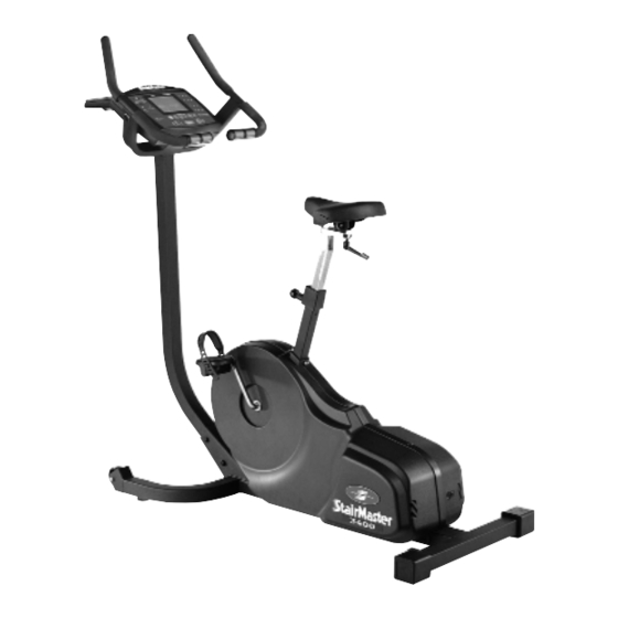
Before leaving the StairMaster manufacturing facility in Tulsa, Oklahoma, your StairMaster ® Momentum cycle ergometer was thoroughly inspected and tested to ensure proper operation. The major parts of the StairMaster Momentum 3400 CE and 3800 RC are shown in Figures 1 and 2. Console Seat... -
Page 12: Table 1: Dimensions Of The Momentum Cycle Ergometer
INTRODUCTION Figure 2: Major Parts, 3800 RC Throughout this manual, all references to the left or right side and to the front or back are made as if you were on the machine, ready to exercise. For example, the drive chain is located on the right side of the machine. The dimensions of the machine are listed in Table 1. -
Page 13: Installation Instructions
INSTALLATION INSTRUCTIONS Assemble your machine before use. Machines shipped outside the United States need to be uncrated before they can be assembled; refer to the “Uncrating Instructions” included with your machine for the details. Remove all shipping material and the battery charger from the machine. -
Page 14: Basic Operating Instructions
BASIC OPERATING INSTRUCTIONS ADJUSTMENTS ® You should check two adjustments before using your StairMaster Momentum systems cycle ergometer: the seat and the pedal foot strap length. Seat Height Adjustment on the Momentum 3400 CE Sit on the seat. Put both feet onto the pedals and into the foot straps. Pedal slowly and then stop when one leg is extended and your foot is as close to the floor as possible. -
Page 15: Foot Strap Adjustment On The Momentum 3400 Ce
BASIC OPERATING INSTRUCTIONS Foot strap Adjustment To ensure your feet are properly secured to the pedals, you need to check the position of the foot straps. Position your foot so that the ball of your foot is over the pedal spindle. The pedal foot straps should be tight enough to secure your feet to the pedals but not so tight so as to cut off the circulation. -
Page 16: Basic Instructions For First-Time Users
BASIC OPERATING INSTRUCTIONS BASIC INSTRUCTIONS FOR FIRST-TIME USERS Warm up with light calisthenics and easy stretching exercises for at least five minutes before beginning your exercise program. WARNING IF AT ANY TIME DURING YOUR WORKOUT YOU FEEL CHEST PAIN, EXPERIENCE SEVERE MUSCULAR DISCOMFORT, FEEL FAINT, OR ARE SHORT OF BREATH, STOP EXERCISING IMMEDIATELY. -
Page 17: Rest Periods
BASIC OPERATING INSTRUCTIONS Select an intensity level that allows you to stay at a comfortable pace. Harder is not always better. Exercise at a level that is consistent with your fitness level. Rest Periods You can stop and rest as many times as necessary for up to one minute for each rest period during all programs. -
Page 18: General Exercise Guidelines
GENERAL EXERCISE GUIDELINES SETTING A GOAL The first step to a successful exercise program is to set realistic goals and objectives. Are you wanting an exercise program that is geared to build muscle, maintain muscle tone, or lose weight? In order to ensure that you fully receive all the benefits of a sound exercise program, you need to first identify the existence (if any) of risk factors that may influence the design of your exercise program. -
Page 19: Exercise Principles
-Maintenance Stage - 6 months plus; moderate to high intensity; moderate to high duration. *Note: Some of the material contained in this section is adapted from The StairMaster ® Fitness Handbook 2nd Ed. , James A Peterson, and Cedric X. Bryant (editors), Sagamore Publishing, 1995. -
Page 20: Heart Rate Monitoring
HEART RATE MONITORING HEART RATE INPUT ® Contact heart rate and telemetry (e.g., Polar ) heart rate signal detection is available. The default heart rate input option is "BOTH LOCKED." If a telemetry signal is detected first, contact heart rate signals are inhibited from being detected throughout the rest of the workout session and vice-versa. -
Page 21: Error Messages
HEART RATE MONITORING There are four options to handle heart rate input signals. Press the [SELECT] key to scroll through the options until you find the one option that suits your needs. Press the [ENTER] key to select that option. “... -
Page 22: Telemetry Heart Rate
Heart rate monitoring is not possible. TELEMETRY HEART RATE ® ® The StairMaster Momentum features telemetry (Polar ) heart rate monitoring. The system consists of the receiver, located on the stepper, and a transmitter belt (purchased separately) worn across your chest. The monitoring function is activated as soon as you strap on the chest belt and step within range of the receiver in the machine. -
Page 23: Maintaining The Transmitter Belt
Do not use abrasives or chemicals such as steel wool or alcohol for cleaning, as they can damage the electrodes permanently. You can order replacement belts from StairMaster, Polar Electro, Inc., or your local fitness store: StairMaster 800-331-3578 P/N 64000 Polar Electro, Inc. -
Page 24: Contact Heart Rate
CONTACT HEART RATE CONTACT HEART RATE ® The StairMaster Momentum features a digitized contact heart rate monitoring system. Through the use of stainless steel sensors built into the upper handles and sophisticated software, heart rate can be checked at any time during a workout. -
Page 25: Momentum Systems Console
MOMENTUM SYSTEMS CONSOLE ® The StairMaster Momentum systems console is divided into seven sections: the display window, the workout options, the numeric keypad, the entertainment keypad, the workout statistics, the stop key, and the intensity level keys (see Figure 5). - Page 26 MOMENTUM SYSTEMS CONSOLE NUMERIC KEYPAD The numeric keypad is located on the right side of the console. Before the exercise program begins, the numbers are used to enter data in response to the console prompts. • Enter - Confirms workout selections and stores the informa- tion used by the console to calculate workout statistics.
-
Page 27: Workout Statistics
MOMENTUM SYSTEMS CONSOLE Workout Statistics During the exercise program, the Stats keys are used to track workout statistics which are then shown in the display window. Pressing the [SELECT] key turns off the scanning feature and shows the statistic of choice in the display window. Pressing the [SCAN] key will prompt the console to cycle through the following statistics: •... -
Page 28: Exercise Program Keypad
MOMENTUM SYSTEMS CONSOLE EXERCISE PROGRAM KEYPAD The exercise keypad is located below the display and to the left of the function keypad. While the console is in the “SELECT WORKOUT” mode, press one of the exercise program keys to preview the desired workout. There are six workout programs with the following standard defaults (pressing [ENTER] without inputting data first will prompt the console to enter these values): •... -
Page 29: The Fat Burner Program
MOMENTUM SYSTEMS CONSOLE on the selected intensity level, with 2 levels equating to one vertical bar. The Fat Burner Program The Fat Burner program is a 60-interval workout designed for people just starting a weight control program. The relative intensity level is indicated on the profile and any changes in the intensity level will continue for the remainder of the program. -
Page 30: The Constant Heart Rate Program
MOMENTUM SYSTEMS CONSOLE during an EXERCISE interval. The intensity level shown during an EXERCISE interval is indicative of your current speed. However, the current speed during a REST interval is equal to a scaled percentage of the displayed intensity level. Note that the program profile does not change at any time during the workout session. -
Page 31: The Fitness Test Programs
MOMENTUM SYSTEMS CONSOLE THE FITNESS TEST PROGRAMS Understanding Submaximal Exercise Testing ® Before using the StairMaster Momentum for submaximal exercise testing, it should be noted that all submaximal fitness tests make several assumptions: • That a steady-state heart rate is obtained for each exercise workload. - Page 32 MOMENTUM SYSTEMS CONSOLE no longer influence heart rate, and a linear relationship exists. As the heart rate rises above 150, the heart-rate/oxygen uptake relationship becomes curvilinear. The third assumption involves maximal heart rate. Maximal heart rate is the greatest heart rate that can be measured when an individual is exercising to the point of volitional fatigue (i.e., exhaustion) during a graded exercise test.
-
Page 33: Pretest Screening
The StairMaster Submaximal Fit Test The StairMaster branching protocol is a series of 3-minute stages of continuous exercise at increasing intensity. The first stage is a warmup at approximately 4 METs. The intensity of the remaining stages is based on the... -
Page 34: Figure 5: Momentum Systems Console
115 to 150 beats/min range to predict VO 2max The test typically lasts from 9 to 15 minutes. In the StairMaster protocol, each work rate is performed for 3 minutes, with heart rates recorded during the final 4 seconds of the 2 and 3 minutes of each stage. -
Page 35: Figure 6: Stairmaster
MOMENTUM SYSTEMS CONSOLE ® Figure 6: StairMaster Fitness Protocol First W o rk L evel 4 M E T s If H R < 1 00 If 10 0 <= H R < = 1 20 If H R > 1 20... -
Page 36: Turning On The Stairmaster Fitness Test
Turning on the StairMaster Fitness Test The StairMaster fitness test may be taken using either a chest strap (telemetry), or by using the specialized contact heart rate grips. 1. Press [ ], [9], [0], [ENTER], on the console keypad. Make sure to press in the middle of each key and be aware that the corresponding numbers will not show in the console display. -
Page 37: Console Codes
MOMENTUM SYSTEMS CONSOLE CONSOLE CODES There are 5 groups of different codes; Customization [codes start with 3], Machine Status [codes start with 4], Diagnostic [codes start with 6 or 7], Configuration [codes start with 8], and Fitness Testing [codes start with 9]. The first group of codes are customization codes and are used to set defaults such as units, language, heart rate input type, etc. - Page 38 MOMENTUM SYSTEMS CONSOLE 1. Change the workout time by pressing [LEVEL: ^], [3 , [0]. The console will display “MAX TIME.” Press [ENTER]. The console will then display the current time limit. Use the keypad to enter the desired time, then press [ENTER].
-
Page 39: Machine Status Codes
MOMENTUM SYSTEMS CONSOLE Machine Status Codes [ ^ ] [ 4 ] [ 0 ] display machine run time in hours [ ^ ] [ 4 ] [ 1 ] display number of workouts [ ^ ] [ 4 ] [ 2 ] display distance traveled [ ^ ] [ 4 ] [ 3 ] display software rev [ ^ ] [ 4 ] [ 4 ] display machine type [ ^ ] [ 4 ] [ 5 ] -N/A-... - Page 40 MOMENTUM SYSTEMS CONSOLE [ ^ ] [ 6 ] [ 2 ] [ENTER] Test serial port Performs a serial loop back test. Select the CSAFE RS-232 selection. You will need a loop-back test cable (PN 040051-001) inserted into the appropriate connector port to successfully run this test. Console will display either “PASS”...
-
Page 41: Configuration Codes
Fitness Testing Codes ® See pg. 23-28 [ ^ ] [ 9 ] [ 0 ] [ENTER] StairMaster Fitness Test [ ^ ] [ 9 ] [ 1 ] [ENTER] N/A [ ^ ] [ 9 ] [ 2 ] [ENTER] N/A... -
Page 42: Maintenance Instructions
MAINTENANCE INSTRUCTIONS HELPFUL HINTS ® If you keep your StairMaster Momentum systems cycle ergometer properly serviced and in good condition, it will operate more efficiently and last longer. It is strongly recommended that you adhere to the maintenance service guidelines presented in this Owner’s Manual. -
Page 43: Resetting The Maintenance Timer
MAINTENANCE INSTRUCTIONS machine first arrives due to testing at the manufacturing facility. • [ ^ ] [ 4 ] [ 1 ] Number of workouts • [ ^ ] [ 4 ] [ 2 ] Distance traveled • [ ^ ] [ 4 ] [ 3 ] Software revision number •... -
Page 44: Weekly Inspection
The salt in perspiration will damage unpainted surfaces. Repair the damaged area with a ® touch-up paint kit provided by StairMaster Health & Fitness Products, Inc. (part number 22181). Pedals: Inspect the pedal foot straps at both the inside and outside attachment sites. - Page 45 MAINTENANCE INSTRUCTIONS To adjust the tension: • Loosen the idler Screw assembly screw so that 22246 the idler pulley can slide 5/8 Washer up and down. • Slide the idler pulley up Main frame Idler assy or down to tighten or 25622 loosen the belt.
-
Page 46: Table 3: Preventive Maintenance Schedule
MAINTENANCE INSTRUCTIONS Table 5. Preventive Maintenance Schedule e l c y l i r e t & , r e e l c y l i t u l e l c & , k e , r e r e t t u l e l c &... -
Page 47: Troubleshooting Guidelines
To order a replacement part, or to get help with the troubleshooting process, contact the Customer Service Depart- ment of StairMaster Health & Fitness Products, Inc. at (800) 331-3578. International customers should contact their local distributor or call (425) 823-1825. -
Page 48: Systematic Electrical Troubleshooting
SYSTEMATIC ELECTRICAL TROUBLESHOOTING okay to use the machine with the battery charger connected. After 48 hours, repeat step 3 - 4. If the voltage measured is below 6.0 VDC then the battery is bad. Plug the battery connector back into the power control board. Test the main cable. - Page 49 Plug the load resistor back into the power control board. Check the main cable assembly for continuity and cross check ® each wire in the cable to check for shorted wires. Call StairMaster Customer Service at (800) 331-3578 for assistance. International customers should contact their local distributors.
-
Page 50: Systematic Mechanical Troubleshooting
SYSTEMATIC MECHANICAL TROUBLESHOOTING SYSTEMATIC MECHANICAL TROUBLESHOOTING These steps should be performed in exactly the order written. Refer to the "Parts Removal and Replacement" section of this manual for any disassembly and assembly instructions. Remove the side covers. Adjust the HTD belt so that the belt is positioned centered on the large HTD pulley and the idler pulley assembly. -
Page 51: Console Diagnostic Tests
[STOP] while in the DIAGNOSTIC mode. Please note that there may be addition verbiage on the display other than is listed in this manual. The Momentum ® console is used on other StairMaster equipment. Diagnostic Codes [ ^ ] [ 6 ] [ 0 ] Test display... -
Page 52: Serial Port Test
CONSOLE DIAGNOSTIC TESTS 2. Firmly press each button except [CLEAR]. The name of the key will be shown in the display window. Press [CLEAR] to end the test. Serial Port Test This test verifies that the RS 232 port used for linking to commercial entertain- ment systems is working. -
Page 53: Tach Test
CONSOLE DIAGNOSTIC TESTS Tach Test If you do not have resistance, perform the tach test. The tach test will tell you the tach signal, in revolutions per minute (RPMs), picked up by the console. 1. Press [ LEVEL: ^ ], [ 6 ], [ 6 ], [ENTER]. The console will display “TAR TACH ACT”. -
Page 54: Contact Heart Rate
CONSOLE DIAGNOSTIC TESTS Contact Heart Rate Test The contact heart rate system is made up of the console and the contact heart rate sensor handles. Remember that even when operating properly, the contact Heart Rate system will not work for everyone. If you suspect you have a problem with your system, have someone else try it before performing the following troubleshooting steps: 1. -
Page 55: Telemetry (Polar ) Heart Rate Test
CONSOLE DIAGNOSTIC TESTS Telemetry (Polar ® ) Heart Rate Test The telemetry heart rate system is made up of the console, the heart rate receiver, and the chest strap (available separately). You can test each component by performing the following steps: 1. -
Page 56: Parts Removal And Replacement
PARTS REMOVAL AND REPLACEMENT ALTERNATOR Remove the side covers. Mark (by color) the location of each wire attached to the alternator (see Wire Connections figure). Remove the wires from the alternator. Loosen and remove the alternator mounting screw on the slotted brace. Loosen the alternator adjustment nut and pivot the alternator down to loosen the alternator (poly-v) belt. -
Page 57: Covers
PARTS REMOVAL AND REPLACEMENT COVERS WARNING TO REDUCE THE RISK OF INJURY, DO NOT OPERATE THE MACHINE WHILE THE COVERS ARE REMOVED. DO NOT ROTATE THE PEDALS WHILE ANYONE'S HANDS ARE INSIDE THE MACHINE. The Momentum 3400 CE / 3800 RC cycle ergometer is protected by two large side covers. -
Page 58: Console
PARTS REMOVAL AND REPLACEMENT Move the crank to about the eleven o’clock position on the left side to get the left side cover over the crank and off the machine. Once the left cover is off the frame, move the cranks to the one o’clock position on the right side and remove the right cover. -
Page 59: Seat (3300 Ce)
PARTS REMOVAL AND REPLACEMENT Console Handlebar assembly Handlebar assembly screws (Qty - 4) Frame tube Reinstall in the reverse order. SEAT 3300 CE Seat Rotate the seat handle counter clockwise and remove Seat slider Seat mounting screw the seat handle and washer from the seat slider. - Page 60 PARTS REMOVAL AND REPLACEMENT 3900 RC The seat pads can be removed while the seat is in the seat track. Pop off the finishing cap with a flat blade screwdriver, and then loosen and remove the four mounting bolts from each seat pad and lift the pad free. To remove the seat from the seat track: Loosen and remove the nyloc nut and flat washer from the rear of the seat track.
-
Page 61: Seat Post (3400 Ce)
PARTS REMOVAL AND REPLACEMENT SEAT POST (3400 CE) Unsnap the seat post cover cap from the frame by pulling up on the bottom edges of the cover cap. Allow the seat post cover cap to rest freely on the seat post. Rotate the seat handle counterclockwise to until it is unthreaded from the seat. -
Page 62: Seat Handle (3400 Ce)
PARTS REMOVAL AND REPLACEMENT SEAT HANDLE (3400 CE) Rotate the seat handle counterclockwise until it is unthreaded from the seat. Remove the seat handle and washer from the seat slider. On the replacement handle, apply a thin layer of grease on the threads from half way to the end of the threads. -
Page 63: High Torque Drive (Htd) Belt
PARTS REMOVAL AND REPLACEMENT HIGH TORQUE DRIVE (HTD) BELT Remove both side covers. Loosen the idler assembly screw and slide the pulley down, loosening the belt. Screw 22246 5/8 Washer Main frame Idler assy 25622 Pull the belt off the large HTD sprocket slide it over the right crank arm. Remove the belt from the small HTD sprocket. -
Page 64: Intermediate Poly-V Pulley Assembly
PARTS REMOVAL AND REPLACEMENT Tighten the alternator mounting screw and alternator adjustment nut. Verify .25" (0.6 cm) of play in the belt and .10" gap between speed sensor and the speed sensor disk. Alternator belt adjustment nut Speed sensor 21445 Main frame .10 Max Speed sensor disk... -
Page 65: Pedals
PARTS REMOVAL AND REPLACEMENT Reverse the steps to reinstall the parts. Snap ring 20206 (21509) Pulley assy 25605 Thrust washer 4 x 21509 (24056) Main frame Bearing 2 x 24056 (21509) Small HTD assy 25603 PEDALS Use a 15-mm pedal wrench or a 5/8" open end wrench to loosen and remove the pedals from the crank. -
Page 66: Crank And Bottom Bracket Assembly
PARTS REMOVAL AND REPLACEMENT Apply a small amount of multi-purpose grease to the threads of the pedal spindle before reinstalling the pedals on the crank. CRANK AND BOTTOM BRACKET ASSEMBLY Remove the side covers. Remove the HTD belt. Remove the left pedal. Loosen and remove the bottom bracket jam nut located on the left side of the crank. - Page 67 PARTS REMOVAL AND REPLACEMENT Install the round, metal crank shield, the jam nut and the pedal onto the left side of the crank. Remember, the jam nut and the pedal have reverse threads (tighten them in the counterclockwise direction). Adjust the side play in the crank by tightening or loosening the left side bearing nut with a 32-mm cone wrench.
-
Page 68: Grounding Instructions
GROUNDING INSTRUCTIONS ® The StairMaster Momentum systems cycle ergometer must be grounded. If it should malfunction or break down, grounding provides the path of least resistance for the electric current, thereby reducing the risk of electric shock. This machine is equipped with a cord having an equipment-grounding conductor and a grounding plug. -
Page 69: Notice Of Fcc Compliance
• Consult the dealer or an experienced radio/TV technician for help. WARNING CHANGES OR MODIFICATIONS TO EQUIPMENT NOT ® EXPRESSLY APPROVED BY STAIRMASTER HEALTH & FITNESS PRODUCTS, INC. COULD VOID THE USER'S AUTHORITY TO OPERATE THIS EQUIPMENT. Canadian Doc Class B Compliance... -
Page 70: Important Phone Numbers
IMPORTANT PHONE NUMBERS If you need assistance, please have both the serial number of your machine and the date of purchase available when you contact the appropriate StairMaster ® Health & Fitness Products, Inc. office listed below. OFFICES IN THE UNITED STATES... -
Page 71: Battery Recycling Centers
BATTERY RECYCLING CENTERS After installing a new battery, you will need to properly dispose of (recycle) your old lead-acid battery. Most federal and state regulations require lead-acid batteries be recycled. Do not throw away old batteries. Lead is a heavy metal and is toxic to living organisms. - Page 72 BATTERY RECYCLING CENTERS STATE ADDRESS PHONE NUMBER New Jersey 131 Industrial Ave. (201) 641-5900 Hasbrouck Hgts., NJ 07604 New York 26 Corporate Circle (315) 437-1788 E. Syracuse, NY 13057 Ohio, Central Rickenbacker ANG (513) 851-3838 Bldg. 1073 Columbus, OH 43217 Ohio, North 2635 Hamilton Ave.
-
Page 73: Figure 8: Cover Fasteners
FIGURES Figure 8: Cover Fasteners Page 65... -
Page 74: Figure 9: Cover Fastener Location, 3400 Ce
FIGURES Figure 9: Cover Fastener Locations, 3400 CE Page 66... -
Page 75: Figure 10: Cover Fastener Location, 3800 Rc
FIGURES Figure 10: Cover Fastener Location, 3800 RC Page 67... -
Page 76: Figure 11: Right Side View, 3400 Ce
FIGURES Figure 11: Right Side View, 3400 CE Page 68... -
Page 77: Figure 12: Right Side View, 3800 Rc
FIGURES Figure 12: Right Side View, 3800 RC Page 69... -
Page 78: Figure 13: Seat Post Assembly, 3400 Ce
FIGURES Figure 13: Seat Post Assembly, 3400 CE Seat 25539 Seat post mount 25544 Washer 11137 Seat handle Seat post 11251 25520 Spring clip 25521 Seat post cover cap 25542 Seat post end cap 25542 Screw 22275 Page 70... -
Page 79: Figure 14: Seat Assembly, 3800 Rc
FIGURES Figure 14: Seat Assembly, 3800 RC Page 71... -
Page 80: Figure 15: Seat Track Assembly, 3800 Rc
FIGURES Figure 15: Seat Track Assembly, 3800 RC Page 72... -
Page 81: Figure 16: Intermediate Poly-V Assembly
FIGURES Figure 16: Intermediate Poly-V Assembly Snap ring 20206 (21509) Pulley assy 25605 Thrust washer 4 x 21509 (24056) Main frame Bearing 2 x 24056 (21509) Small HTD assy 25603 Page 73... -
Page 82: Figure 17: Crank Assembly
FIGURES Figure 17: Crank Assembly HTD Sprocket Assy Pedals, pair 25601 Crank shield 25642 24083-03 Jam nut 24073 RH Bearing nut assy 24434 Jam nut 24073 LH Bearing nut assy Bicycle Crank 24435 25643 Main frame Install with flange to the inside Page 74... -
Page 83: Figure 18: Alternator/Flywheel Assembly
FIGURES Figure 18: Alternator/Flywheel Assembly Page 75... -
Page 84: Figure 19: Wire Connections
FIGURES Figure 19: Wire Connections Page 76... -
Page 85: Figure 20: Power Control Board Plug-Ins
FIGURES Figure 20: Power Control Board Plug Ins Page 77... -
Page 86: Figure 21: Wiring Diagram
FIGURES Figure 21: Wiring Diagram C o ns o le C 4 0 P/N 27 79 6 M u s t con f ig u re fo r C ycle Us e ^8 0 3 4 0 0 U ppe r M a in C a ble P/N 25 46 2 3 8 0 0 M a in C a ble C on s ole to I n lin e C o n n e ctor...
Need help?
Do you have a question about the MOMENTUM C40 and is the answer not in the manual?
Questions and answers