kozy heat 911XL Installation And Operation Manual
Direct vent insert
Hide thumbs
Also See for 911XL:
- Installation and operation manual (57 pages) ,
- Installation manual (102 pages)
Table of Contents
Advertisement
Quality Fireplaces for Life
DIRECT VENT INSERT
WARNING
: This product must be installed by
a licensed plumber or gas fitter when installed
in the Commonwealth of Massachusetts.
IMPORTANT: Installation of a CO detector is
required in the fireplace room when installed in
the Commonwealth of Massachusetts.
This appliance may be installed in an aftermarket permanently located, manufactured (mobile) home,
where not prohibited by local codes.
A manufactured home (USA only) or mobile home OEM installation must conform with the Manufac-
tured Home Construction and Safety Standard, Title 24 CFR, Part 3280, or when such a standard is
not applicable, the Standard for Manufactured Home Installations, ANSI/NCSBCS A225.1, or Stan-
dard for Gas Equipped Recreational Vehicles and Mobile Housing, CSA Z240.4
WARNING:
If the information in these instructions are not followed exactly, a fire or
explosion may result, causing property damage, personal injury or loss of life.
◙
Do not store or use gasoline or other flammable vapors and liquids in the vicinity of this or
any other appliance.
IF YOU SMELL GAS:
◙ Do not light any appliance.
◙ Do not touch any electrical switch: do not use any phone in your building.
◙ Immediately call gas supplier from a neighbors phone. Follow the gas supplier instructions.
◙ If you cannot reach your gas supplier, call the fire department.
◙ Installation and service must be performed by a qualified installer, service agency or the gas
supplier.
This appliance is only for use with the type (s) of gas indicated on
the rating plate. A conversion kit is supplied with the appliance.
OPERATION MANUAL
INSTALLER: LEAVE THIS MANUAL WITH THE APPLIANCE.
CONSUMER: RETAIN THIS MANUAL FOR FUTURE REFERENCE.
www.kozyheat.com
INSTALLATION
AND
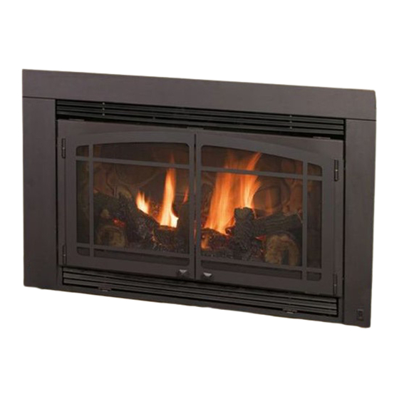
Shown with Rock Refractory and
Black Prairie screen doors.
See your dealer for these and other options.
October 2009
911XL-R-10
Advertisement
Table of Contents
Troubleshooting

Related Manuals for kozy heat 911XL


Summary of Contents for kozy heat 911XL
-
Page 1: Direct Vent Insert
◙ Installation and service must be performed by a qualified installer, service agency or the gas supplier. This appliance is only for use with the type (s) of gas indicated on the rating plate. A conversion kit is supplied with the appliance. www.kozyheat.com October 2009 911XL-R-10... - Page 2 Please retain this owner’s manual for future reference. CONGRATULATIONS! We welcome you as a new owner of a Kozy Heat gas fireplace. Kozy Heat products are designed with superior components and materials and assembled by trained craftsmen who take pride in their work. The burner and valve assembly are 100% test-fired and the complete fireplace is thoroughly inspected before packaging to ensure that you receive a quality product.
-
Page 3: Table Of Contents
Air Duct Removal Millivolt Board Removal #9XL-MSP Masonry Side Panel Installation (optional) Restrictor VENTING INSTALLATION Kozy Heat #815-CL Co-Linear Vent System Run Vent System Through Existing Chimney Position Fireplace Insert Attach Air Duct To Insert COMPLETE FAN WIRING INSTALLATION Complete Fan Wiring Installation... -
Page 5: Safety Information
SAFETY INFORMATION This fireplace has been tested to and complies with ANSI Z21.88b-2008·CSA 2.33b-2008·M02 “VENTED GAS FIREPLACE HEATERS” by OMNI-Test Laboratories, Portland, OR. Installation must conform with local building codes or in the absence of local building codes, with the National Fuel Gas Code, ANSIZ223.1/NFPA 54 - Current Edition, or the Natural or Propane Installation Code, CSAB149.1 Installation and repair should be done only by a qualified service person. -
Page 6: Features
Bedroom and mobile home approved High - Low regulator *Automatic fan kit (2) - 75 CFM Refractory brick lining Minnesota Energy Code compliant to 50 pascals * Model #911XL only WEIGHT Fireplace Weight (as packaged for shipment) 138 lbs. (62.6 kg) OPTIONAL FEATURES Grills (required) –... -
Page 7: Commonwealth Of Massachusetts Information
COMMONWEALTH OF MASSACHUSETTS REQUIREMENTS NOTE: The following requirements reference various Massachusetts and national codes not contained in this manual. For all sidewall horizontally vented gas fueled equipment installed in every dwelling, building or structure used in whole or in part for residential purposes, including those owned or operated by the Commonwealth and where the side wall exhaust vent termination is less than (7) feet above finished grade in the area of the venting, including but not limited to decks and porches, the following requirements shall be satisfied: INSTALLATION OF CARBON MONOXIDE DETECTORS... -
Page 8: Specifications
Millivolt board with burner cover Log set (see page 24) *150 CFM fan with speed control and limit switch Co-linear air duct *911XL only MINIMUM CLEARANCES TO COMBUSTIBLES Insert glass to sidewall: 10” (254 mm) Insert top to mantel: 12” (305 mm) PAGE 6... -
Page 9: Components List
SPECIFICATIONS MODEL #911XL COMPONENTS LIST MODEL #911XL-RAD COMPONENTS LIST (#9XL-770) - Millivolt Board Assembly with 18” Flexible Gas (#9XL-770) - Millivolt Board Assembly with 18” Flexible Gas Line attached Line attached (#700-203) - Manual Gas Shut-off Valve (#700-203) - Manual Gas Shut-off Valve... -
Page 10: Existing Fireplace Specifications
EXISTING FIREPLACE SPECIFICATIONS THIS INSERT IS APPROVED FOR INSTALLATION IN MASONRY AND FACTORY-BUILT SOLID FUEL BURNING FIREPLACES. EXISTING FIREPLACE REQUIREMENTS The existing fireplace & chimney must be clean and in good working order and constructed of non-combustible materials. A gas line must be able to be installed to the insert. Provisions made to provide electrical power to operate the insert fan and thermostatic control (if used). -
Page 11: Prepare Existing Fireplace
PREPARE THE EXISTING FIREPLACE PREPARE THE EXISTING FIREPLACE WARNING: CUTTING ANY SHEET-METAL PARTS OF THE FIREPLACE, IN WHICH THE GAS FIREPLACE IS TO BE INSTALLED, IS PROHIBITED. The refractory, glass doors, screen rails, screen mesh and log grates may be removed from existing fireplace before installing this gas fireplace insert. -
Page 12: Fan Direct Wire Installation
911XL-RAD: A speed control, receptacle, and 8 ft. (2.44 m) fan cord have been installed, wired and mounted in an electrical box panel included with fan kit. If hardwiring to the electrical box is desired, the wiring should be run prior to permanently setting the insert in place and connecting the vent system. -
Page 13: Thermostat / Wall Switch / Remote
THERMOSTAT / WALL SWITCH / REMOTE CAUTION: DO NOT CONNECT HIGH NOTE: INSTALLATION OF THERMOSTAT OR WALL VOLTAGE (115V) WIRE TO THE GAS SWITCH SHOULD ONLY BE DONE BY A QUALIFIED VALVE! INSTALLER. If desired, a thermostat (wireless style also available), wall switch, or remote control assembly may be used to turn the fireplace „OFF‟... -
Page 14: Gas Line Connection
1 ½"(38 mm) or less may be drilled through the lower sides or bottom of the firebox in a proper workmanship like manner. This ac- cess hole must be plugged with non-combustible insulation after the gas supply line has been installed. 2” (51 mm) from bottom to gas line WARNING LABEL 911XL / 911XL-RAD NATURAL GAS LP GAS MINIMUM INLET GAS PRESSURE 5.0 inches W.C. -
Page 15: Installation
CONTINUING WITH THIS INSTALLATION. APPROVED VENTING Kozy Heat #815-CL Co-Linear Vent System. Follow instructions on following pages. Selkirk, ICC, American Metals, Security Follow instructions included from vent pipe manufacturer as well as the venting requirements as outlined in this installation manual. -
Page 16: 9Xl-Msp Masonry Side Panel Installation (Optional)
INSTALLATION #9XL-MSP MASONRY SIDE PANEL INSTALLATION (OPTIONAL) IMPORTANT: For use when the insert is installed in an existing masonry opening. This kit must be attached to the air duct (manifold) prior to vent system connection. This kit includes: (1) Right side panel Left side panel (12) sheet metal screws NOTE: If the air duct and masonry side panels are not placed „outside‟... -
Page 17: Venting Installation
VENTING INSTALLATION KOZY HEAT #815-CL CO-LINEAR VENT SYSTEM NOTE: The co-linear pipe included with this vent system is designed to extend up to 25 ft. (7.62 m). If additional length is required, Part #510 is available to extend the venting to a maximum of 40 ft (12.19 m). -
Page 18: Run Vent System Through Existing Chimney
VENTING INSTALLATION RUN VENTING THROUGH EXISTING CHIMNEY We strongly suggest wrapping the first 3 ft.(914 mm) of vent system below the termina- tion cap with non-faced fiberglass insulation (secure with wire) before running it through the existing chimney. This will prevent cold air from coming down the existing chimney. NOTE: If offsets are present in existing chimney, it may be easier to place a weighted rope around the end of each pipe to guide them through it. -
Page 19: Position Fireplace Insert
POSITION FIREPLACE INSERT CONNECT VENT SYSTEM TO AIR DUCT Place air duct (previously removed from insert top, page 13) into the ex- isting fireplace opening. Place a bead of sealant (provided) around 4” exhaust pipe. Slide exhaust pipe inside 4" collar air duct. Secure with (3) ½" self-tapping screws, provided. -
Page 20: Complete Fan Wiring Installation
#911XL #911XL-RAD OPTIONAL FAN KIT #911-028 #911XL-RAD with optional fan kit #911-028 If not previously done, turn gas valve and manual shut off valve to „OFF‟. Disconnect gas line from manual shut off valve. Remove lower grill if previously installed. -
Page 21: Millivolt Board
MILLIVOLT BOARD INSTALLATION MILLIVOLT BOARD INSTALLATION WARNING: DO NOT OPERATE THIS FIREPLACE WITHOUT SEALING GASKET (LOCATED UNDER THE MILLIVOLT BOARD) IN PLACE. IF GASKETING IS DAMAGED, IT MUST BE REPLACED. Place millivolt board in firebox, aligning holes in the millivolt board with mounting studs in the firebox bottom. -
Page 22: Millivolt Board Removal
MILLIVOLT BOARD REMOVAL (after installation) CAUTION: If the burner and/or pilot have been burning, use the appropriate protection to avoid burns or damage to personal property before removing any components. Turn gas control knob to the „OFF‟ position. Shut off gas supply at the manual shut-off valve. Disconnect gas line flex tube from the manual shut-off valve. -
Page 23: Zc Shroud Assembly And Installation
ZC SHROUD ASSEMBLY AND INSTALLATION Shroud assembly includes: (1) Shroud top (8) Phillips head screws (1) Shroud left side (2) Shroud extensions (1) Shroud right side with on/off rocker switch mounting hole IMPORTANT: You will need the following items from the insert components packet: Rocker switch wires On/Off Rocker switch You will also need the grill set (sold separately) . -
Page 24: Masonry Shroud Assembly And Installation
MASONRY SHROUD ASSEMBLY AND INSTALLATION Shroud assembly includes: (1) Shroud top (8) Phillips head screws (1) Shroud left side (1) Set „inside fit‟ brackets (1) Shroud right side with on/off rocker switch mounting hole IMPORTANT: You will need the following items from the insert components packet: Rocker switch wires On/Off Rocker switch You will also need the upper grill from the grill set (sold separately) . - Page 25 MASONRY SHROUD ASSEMBLY AND INSTALLATION IMPORTANT- MOUNTING BRACKET ORIENTATION The right mounting bracket is notched out at the bottom. Figure 1. Flanges on both mounting brackets face the inside of insert. Figure 1. Align holes in mounting brackets to the corresponding holes in insert face, making sure brackets are positioned as shown in Figure 1.
-
Page 26: Log Set Installation
#936-50E LOG SET INSTALLATION ATTENTION: If converting to LP (propane) gas, do so now before installing log set. Follow instructions included with conversion kit. NOTE: Log numbers are located on the bottom of each log. Refer to following instructions and illustrations for proper placement. CAUTION: Do not place logs directly over burner port holes. -
Page 27: Lighting And Shutdown
LIGHTING AND SHUTDOWN FOR YOUR SAFETY - READ BEFORE LIGHTING WARNING: IF YOU DO NOT FOLLOW THESE INSTRUCTIONS EXACTLY, A FIRE OR EXPLOSION MAY RESULT, CAUSING PROPERTY DAMAGE, PERSONAL INJURY OR LOSS OF LIFE. DUE TO HIGH SURFACE TEMPERATURES, KEEP CHILDREN, CLOTHING AND FURNITURE AWAY. This appliance needs fresh air for safe operation and must be installed so there are provisions for adequate combustion and ventilation air. - Page 28 VALVE & PILOT ASSEMBLY COMPONENTS THERMOCOUPLE THERMOPILE PILOT HOOD ELECTRODE HI /LO FLAME ADJUSTMENT KNOB GAS CONTROL KNOB PIEZO IGNITOR VALVE TERMINALS ON/OFF ROCKER SWITCH PAGE 26...
- Page 29 LIGHTING AND SHUTDOWN (cont.) LIGHTING 5 MINUTES Set thermostat to the lowest setting, if installed. Turn off all electrical power to the appliance. (Fan). Open lower grill to access the gas valve & controls. A. Push gas control knob in slightly and turn clockwise to “OFF”.
- Page 30 LIGHTING AND SHUTDOWN (cont.) TURN BURNER OFF G. To turn the burner „OFF‟, depress the ON/OFF rocker switch to „OFF‟, flip „off‟ wall switch or adjust setting on the thermostat or remote control. NOTE: The pilot will stay lit. TURN PILOT OFF H.
-
Page 31: Pressure Testing
PRESSURE TESTING IMPORTANT NOTICE: Pressure check taps for the manifold (outgoing) and inlet (incoming) pressure have been incorporated into the valve. The pressure tap marked „OUT‟ measures outgoing pressure and the pressure tap marked „IN‟ measures incoming pressure. Follow instructions below for proper testing procedures. NOTE: The appliance and its individual shutoff valve must be disconnected from the gas supply piping system during any pressure testing of that system at pressures in excess of ½... -
Page 32: Finalizing The Installation
FINALIZING THE INSTALLATION FLAME APPEARANCE: Flame appearance is affected by several factors including altitude, venting configuration and fuel quality. Although the venturi setting has been factory set, adjustments may be necessary for optimal performance and visual aesthetics. When fireplace is first lit, the flames will be blue. The flames will gradually turn yellowish-orange during the first 15 minutes of opera- tion. -
Page 33: Restrictor Usage / Troubleshooting / Installation / Modification
FINALIZING THE INSTALLATION RESTRICTOR USAGE: Turn the fireplace on and allow to burn for 15 minutes. If flames indicate there is excessive draft (flickering, short flames) or insufficient draft (lifting or ghosting flames) a restrictor may be necessary, or the previously installed restrictor may need to be modified or removed. WARNING: TO AVOID PROPERTY DAMAGE OR PERSONAL INJURY, ALLOW FIREPLACE INSERT AMPLE TIME TO COOL BEFORE MAKING ANY ADJUSTMENTS AND / OR INSTALLATIONS. -
Page 34: Seasonal Heat Dump
FINALIZING THE INSTALLATION SEASONAL HEAT DUMP This fireplace insert has been manufactured with a heat dump damper located at the inside top of firebox. This allows infinite control over the amount of heat emitted into the living area without affecting flame height. INSTALLER: Please install this fireplace insert with the heat dump in the closed position. -
Page 35: Maintenance
MAINTENANCE The appliance is required to be inspected at least once a year by a MILLIVOLT BOARD SYSTEM professional service person. The compartment below the firebox (behind the lower grill) must be cleaned Annual cleaning of the burner system is required. at least once a year, more frequent cleaning may be required due to excessive lint from carpeting, bedding materials, or other fibrous materials. -
Page 36: Troubleshooting
TROUBLESHOOTING CAUTION: THE FOLLOWING MUST BE PERFORMED BY A QUALIFIED TECHNICIAN. NO SPARK FROM ELECTRODE TO PILOT WHEN PIEZO BUTTON IS TRIGGERED. A. Check wiring at back of piezo for proper connection. B. Check wiring at electrode for proper connection. C. - Page 37 TROUBLESHOOTING BURNER WILL NOT LIGHT A. Gas control knob not turned to „ON‟. B. „ON‟/„OFF‟ switch not turned on. C. Remote, wall switch or thermostat not turned „ON‟. D. Plugged main burner orifice. E. Remote, wall switch ,thermostat or „ON/ OFF‟ switch wires defective. ♦...
- Page 38 TROUBLESHOOTING PILOT AND BURNER EXTINGUISH WHILE IN OPERATION A. No LP (propane) in tank. ♦ Check tank and refill if necessary. B. Glass frame assembly not installed correctly. ♦ Refer to page 9 in this manual for proper glass frame assembly installment instructions. C.
-
Page 39: Replacement Parts List
REPLACEMENT PARTS LIST Replacement parts are available through your local dealer. Contact them for availability and pricing. 911XL MILLIVOLT BOARD AND PARTS 9XL-770 MTK Millivolt Board - Nat Gas 700-092 Millivolt Generator 9XL-771 MTK Millivolt Board - LP Gas 700-059... -
Page 40: Warranty
PAGE 38... - Page 41 PAGE 39...
Need help?
Do you have a question about the 911XL and is the answer not in the manual?
Questions and answers