Table of Contents
Advertisement
Quick Links
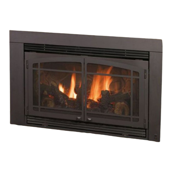
Quality Fireplaces for Life
DIRECT VENT INSERT
WARNING
: This product must be installed by
a licensed plumber or gas fitter when installed
in the Commonwealth of Massachusetts.
IMPORTANT: Installation of a CO detector is
required in the fireplace room when installed in
the Commonwealth of Massachusetts.
This appliance may be installed in an aftermarket perma-
nently located, manufactured (mobile) home, where not
prohibited by local codes.
A manufactured home (USA only) or mobile home OEM installation must conform with the Manufac-
tured Home Construction and Safety Standard, Title 24 CFR, Part 3280, or when such a standard is
not applicable, the Standard for Manufactured Home Installations, ANSI/NCSBCS A225.1, or Stan-
dard for Gas Equipped Recreational Vehicles and Mobile Housing, CSA Z240.4
WARNING:
If the information in these instructions are not followed exactly, a fire or
explosion may result, causing property damage, personal injury or loss of life.
◙
Do not store or use gasoline or other flammable vapors and liquids in the vicinity of this or
any other appliance.
IF YOU SMELL GAS:
◙ Do not light any appliance.
◙ Do not touch any electrical switch: do not use any phone in your building.
◙ Immediately call gas supplier from a neighbors phone. Follow the gas supplier instructions.
◙ If you cannot reach your gas supplier, call the fire department.
◙ Installation and service must be performed by a qualified installer, service agency or the gas
supplier.
This appliance is only for use with the type (s) of gas indicated on
the rating plate. A conversion kit is supplied with the appliance.
OPERATION MANUAL
INSTALLER: LEAVE THIS MANUAL WITH THE APPLIANCE.
CONSUMER: RETAIN THIS MANUAL FOR FUTURE REFERENCE.
www.kozyheat.com
INSTALLATION
AND
April 2009
911XL-R08
Advertisement
Table of Contents

Related Manuals for kozy heat Jackson XL


Summary of Contents for kozy heat Jackson XL
-
Page 1: Direct Vent Insert
INSTALLATION OPERATION MANUAL INSTALLER: LEAVE THIS MANUAL WITH THE APPLIANCE. CONSUMER: RETAIN THIS MANUAL FOR FUTURE REFERENCE. Quality Fireplaces for Life DIRECT VENT INSERT WARNING : This product must be installed by a licensed plumber or gas fitter when installed in the Commonwealth of Massachusetts. -
Page 3: Table Of Contents
TABLE OF CONTENTS Introduction ..........................2 Safety Requirements ......................... 3 Commonwealth of Massachusetts Requirements………………………………………………………...4 Requirements of Existing Fireplace ................... 5 Insert Fireplace Specifications ....................6 Preparing The Existing Fireplace ....................7 Gas Line Installation Requirements - Minimum/Maximum Pressures ........7-8 Insert Preparation ........................ -
Page 5: Introduction
Please retain this owner’s manual for future reference. CONGRATULATIONS! We welcome you as a new owner of a Kozy Heat gas fireplace. Kozy Heat products are designed with superior components and materials and assembled by trained craftsmen who take pride in their work. The burner and valve assembly are 100% test-fired and the complete fireplace is thoroughly inspected before packaging to ensure that you receive a quality product. - Page 7 SAFETY INFORMATION This fireplace has been tested to and complies with ANSI Z21.88b-2008·CSA 2.33b-2008·M02 “VENTED GAS FIREPLACE HEATERS” by OMNI-Test Laboratories, Portland, OR. Installation must conform with local building codes or in the absence of local building codes, with the National Fuel Gas Code, ANSIZ223.1/NFPA 54 - Current Edition, or the Natural or Propane Installation Code, CSAB149.1 Installation and repair should be done only by a qualified service person.
-
Page 8: Commonwealth Of Massachusetts Requirements
COMMONWEALTH OF MASSACHUSETTS REQUIREMENTS NOTE: The following requirements reference various Massachusetts and national codes not contained in this manual. For all sidewall horizontally vented gas fueled equipment installed in every dwelling, building or structure used in whole or in part for residential purposes, including those owned or operated by the Commonwealth and where the side wall exhaust vent termination is less than (7) feet above finished grade in the area of the venting, including but not limited to decks and porches, the following requirements shall be satisfied: INSTALLATION OF CARBON MONOXIDE DETECTORS... - Page 9 THIS UNIT IS APPROVED FOR INSTALLATION IN FACTORY-BUILT ZERO-CLEARANCE SOLID FUEL AND MASONRY FIREPLACES. WARNING: Failure to use only parts specifically approved with this appliance may result in property damage or personal injury. WARNING: CUTTING ANY SHEET METAL PARTS OF THE FIREPLACE, IN WHICH THIS GAS FIREPLACE INSERT IS TO BE INSTALLED, IS PROHIBITED.
- Page 10 SPECIFICATIONS: Height (top of firebox): 21” Height (top of air duct): 22-3/4” " 410mm Width: 33-3/8” Depth: 16 1/8” " 4 3 4 797mm " 57mm " " 21" 448mm 578mm 533mm " 848mm FRONT RIGHT LEFT WARNING: FAILURE TO POSITION THE PARTS IN ACCORDANCE WITH THESE DIAGRAMS OR FAILURE TO USE ONLY PARTS SPECIFICALLY APPROVED WITH THIS APPLIANCE MAY RESULT IN PROPERTY DAMAGE OR PERSONAL INJURY.
-
Page 11: Preparing The Existing Fireplace
PREPARE THE EXISTING FIREPLACE EXISTING FIREPLACE AND FIREPLACE CHIMNEY MUST BE CLEAN AN IN GOOD WORKING ORDER AND CONSTRUCTED OF NON-COMBUSTIBLE MATERIALS. Trim panels or surrounds shall not seal ventilation openings in the fireplace. Remove the smoke baffle, the damper assembly and, if necessary - the firebrick on the sides and back of the existing fireplace to obtain at least the minimum opening requirements listed on page #5. - Page 12 2. This unit is designed to accept either a 3/8" or 1/2" gas line approved for gas appliances. Consult local building codes to properly size the gas supply line leading to a 3/8" reduction. Also, see the chart below for proper supply line sizing. 3.
-
Page 13: Remove The Air Duct
MILLIVOLT BOARD. Figures C-2 & C-3. Pilot Shield A. Remove(2) nuts securing burner cover. Lift the front of the cover up, then carefully sliding the burner tube off the orifice. Remove entire assembly from the firebox (Figure C-2). Figure C-2 B. -
Page 14: Installing The Insert
D) INSTALLING THE INSERT IMPORTANT: ALL STEPS IN SECTION „A‟ PREPARE THE EXISTING FIREPLACE‟ MUST BE COMPLETED BEFORE CONTINUING WITH THIS INSTALLATION. ##815-CL CO-LINEAR VENT SYSTEMS 815-CL CO-LINEAR VENT SYSTEMS 1. MASONRY SIDE PANEL INSTALLATION - Optional An optional masonry panel kit is available for this insert and includes 1 left panel, 1 right panel and 12 sheet metal screws. These panels are used when the fireplace is installed in an existing masonry opening and must be installed to the air duct (manifold) before the vent system is connected. -
Page 15: Install The Vent System
3. INSTALL THE VENT SYSTEM NOTE: The 4” exhaust pipe and 3” combustion air intake pipe will extend 25 ft.. An optional extension kit (Part #510) is available to extend the #815-CL kit up to a maximum of 40 ft. A. - Page 16 4. RUN THE VENT SYSTEM THROUGH THE EXISTING CHIMNEY We strongly suggest wrapping the first 3 ft. of the vent system below the termination cap with non-faced fiberglass insulation (secure with wire) before running it through the existing chimney. This will prevent cold air from coming down the existing chim- ney.
- Page 17 E) POSITION THE FIREPLACE INSERT: 1. Slide the insert in the fireplace opening. The masonry panels, if used, secured to the air duct must be ‘outside’ the flange at the bottom of the insert . NOTE: If the masonry panels are not „outside‟ the flange, it may cause a rattling noise when the fan is operating. 2.
- Page 18 F) SECURE THE MASONRY SIDE PANELS, IF INSTALLED. 1. With the panels ‘outside’ the flange at the bottom of the insert, align the holes in the masonry side panels to the holes in the face of the insert and secure with 4 - self- tapping screws (2 ea.
-
Page 19: Attach The Shroud
H) ZC SHROUD INSTALLATION: Shroud assembly includes: (1) Shroud top (8) Phillips head screws (1) Shroud left side (2) Shroud extensions (1) Shroud right side with on/off rocker switch mounting hole IMPORTANT: You will need the following items from the components packet included with the unit: (1) Rocker switch wires (1) On/Off Rocker switch A small phillips head screwdriver to assemble the shroud and shroud extensions. -
Page 20: Attach The Shroud
I) ASSEMBLE & ATTACH THE SHROUD Shroud assembly includes: (1) Shroud top (1) Shroud left side (1) Shroud right side with on/off rocker switch mounting hole (1) Set (1 left & 1 right) ‘inside fit’ brackets. (8) Screws Additional Items Needed: Rocker switch &... - Page 21 INSIDE FIT APPLICATIONS: NOTE: INSIDE FIT APPLICATIONS REQUIRE THE „INSIDE FIT MOUNTING BRACKETS‟, INCLUDED WITH THE SHROUD, FOR INSTALLATION. Cut lower end of Remove the glass assembly. Refer to page 8 if necessary. each tab at the location shown. Assemble the shroud, install the upper grill & on/off rocker switch as described on page 17-18 of these instructions.
-
Page 22: Fan Installation
CONNECT THE ROCKER SWITCH WIRES TO THE VALVE Slide the remaining connectors on the rocker switch wire to the top and bottom terminals marked „TH‟ on the valve. Completed Shroud Installation 1.COMPLETE THE FAN INSTALLATION: This unit comes complete with a fan, speed control and temperature limit switch assembly already installed. A three-prong (grounding) plug is attached to the end of the 8 ft. -
Page 23: Log Installation
J) LOG INSTALLATION. See Figures J-1 - J-3. This log set includes: (1) X1 log (1) X4 log (1) X7 log (1) X9 log (1) X2 log (1) X6 log (1) X8 log (1) X10 log (1) X3 log (1) Rock Wool Embers Pkg. (1) Klinker pkg. -
Page 24: Complete The Installation
K) COMPLETE THE INSTALLATION 1. THIS STEP SHOULD ONLY BE DONE BY A QUALIFIED INSTALLER OR SERVICE TECHNICIAN: Perform lighting and shutdown procedures as described on pages #22-24. This should be done prior to replacing the glass so that any necessary adjustments can be made and proper operation and log position verified. 2. - Page 25 THERMOSTAT / WALL SWITCH / REMOTE CAUTION: DO NOT CONNECT HIGH VOLTAGE NOTE: INSTALLATION OF THERMOSTAT OR WALL SWITCH (115V) WIRE TO THE GAS VALVE! SHOULD ONLY BE DONE BY A QUALIFIED INSTALLER. If desired, a thermostat (wireless style also available), wall switch, or remote control assembly may be used to turn the fireplace „OFF‟...
- Page 26 LIGHTING AND SHUTDOWN FOR YOUR SAFETY - READ BEFORE LIGHTING WARNING: IF YOU DO NOT FOLLOW THESE INSTRUCTIONS EXACTLY, A FIRE OR EXPLOSION MAY RESULT, CAUSING PROPERTY DAMAGE, PERSONAL INJURY OR LOSS OF LIFE. DUE TO HIGH SURFACE TEMPERATURES, KEEP CHILDREN, CLOTHING AND FURNITURE AWAY. This appliance needs fresh air for safe operation and must be installed so there are provisions for adequate combustion and ventilation air.
- Page 27 LIGHTING AND SHUTDOWN (cont.) LIGHTING 5 MINUTES Set thermostat to the lowest setting, if installed. Turn off all electrical power to the appliance. (Fan). Open lower grill to access the gas valve & controls. A. Push gas control knob in slightly and turn clockwise to “OFF”.
- Page 28 LIGHTING AND SHUTDOWN (cont.) TURN BURNER OFF G. To turn the burner „OFF‟, depress the ON/OFF rocker switch to „OFF‟, flip „off‟ wall switch or adjust setting on the thermostat or remote control. NOTE: The pilot will stay lit. TURN PILOT OFF H.
- Page 29 PRESSURE TESTING IMPORTANT NOTICE: Pressure check taps for the manifold (outgoing) and inlet (incoming) pressure have been incorporated into the valve. The pressure tap marked „OUT‟ measures outgoing pressure and the pressure tap marked „IN‟ measures incoming pressure. Follow instructions below for proper testing procedures. NOTE: The appliance and its individual shutoff valve must be disconnected from the gas supply piping system during any pressure testing of that system at pressures in excess of ½...
-
Page 30: Maintenance Requirements
N) MAINTENANCE REQUIREMENTS MILLIVOLT BOARD SYSTEM 1. The appliance should be inspected at least once a year Annual cleaning of the burner is required. The burner by a professional service person. tube may be removed for easier access. NOTE: INSTALLATION AND REPAIR SHOULD BE DONE Visually check for blocked port holes, especially near the ONLY BY A QUALIFIED SERVICE PERSON. -
Page 31: Troubleshooting
TROUBLESHOOTING CAUTION: THE FOLLOWING MUST BE PERFORMED BY A QUALIFIED TECHNICIAN. NO SPARK FROM ELECTRODE TO PILOT WHEN PIEZO BUTTON IS TRIGGERED. A. Check wiring at back of piezo for proper connection. B. Check wiring at electrode for proper connection. C. - Page 32 TROUBLESHOOTING BURNER WILL NOT LIGHT A. Gas control knob not turned to „ON‟. B. „ON‟/„OFF‟ switch not turned on. C. Remote, wall switch or thermostat not turned „ON‟. D. Plugged main burner orifice. E. Remote, wall switch ,thermostat or „ON/ OFF‟ switch wires defective. ♦...
-
Page 33: Replacement Parts
REPLACEMENT PARTS LIST Replacement parts are available through your local dealer. Contact them for availability and pricing. 911XL MILLIVOLT BOARD AND PARTS 9XL-770 MTK Millivolt Board - Nat Gas 700-092 Millivolt Generator 9XL-771 MTK Millivolt Board - LP Gas 700-059 Thermocouple 700-023 On/Off Rocker Switch... - Page 35 PAGE 30...
- Page 37 PAGE 31...
Need help?
Do you have a question about the Jackson XL and is the answer not in the manual?
Questions and answers