Table of Contents
Advertisement
Quick Links
Model #911-XXL
Direct Vent Gas Fireplace Insert
INSTALLATION & OPERATING
MANUAL
U.S. PATENT #5,931,154
U.S. PATENT #6,004,493
U.S. PATENT #6,029,655
CAUSE SERIOUS STRUCTURAL AND FIRE HAZARDS AND MAY VOID
READ ALL INSTRUCTIONS CAREFULLY BEFORE INSTALLATION.
FAILURE TO INSTALL THIS FIREPLACE INSERT CORRECTLY CAN
WARNING: If the information in these
instructions are not followed exactly, a fire or
explosion may result causing property damage,
personal injury or loss of life.
Do not store or use gasoline or other flammable vapors
in the vicinity of this or any other appliance.
WHAT TO DO IF YOU SMELL GAS:
‚ Do not try to light any appliance.
‚ Do not touch electrical switches; do not use the
phone in your building.
‚ Immediately call your gas supplier from a neighbor's
phone. Follow the gas supplier's instructions.
‚ If you cannot reach your gas supplier, call the fire
department.
- Installation and service must be performed by a qualified
installer, service agency or the gas supplier.
This appliance may be installed in an aftermarket
permanently located, manufactured (mobile) home, where
not prohibited by local codes.This appliance is only for
use with the type(s) of gas indicated on the rating place.
This appliance is not convertible for use with other
gases, unless a certified kit is used.
IMPORTANT:
YOUR WARRANTY.
www.kozyheat.com
October 2006
Advertisement
Table of Contents

Subscribe to Our Youtube Channel
Related Manuals for kozy heat 911-XXL


Summary of Contents for kozy heat 911-XXL
- Page 1 Do not store or use gasoline or other flammable vapors Model #911-XXL in the vicinity of this or any other appliance. WHAT TO DO IF YOU SMELL GAS: Direct Vent Gas Fireplace Insert ‚...
-
Page 2: Table Of Contents
INDEX Fireplace Insert Specifications ............1 Safety Requirements . -
Page 3: Fireplace Insert Specifications
MODEL JACKSON XXL DIRECT VENT GAS BURNING FIREPLACE INSERT INSTALLATION & OPERATING INSTRUCTIONS IMPORTANT: READ THIS MANUAL BEFORE INSTALLING AND USING THIS FIREPLACE This fireplace has been tested to and complies with ANSI Z21.88-2002 CSA 2.33-2002 “VENTED GAS FIREPLACE HEATERS” by ... -
Page 4: Requirements Of Existing Fireplace
CAUTION: THIS FIREPLACE INSERT IS APPROVED FOR INSTALLATION IN MASONRY AND FACTORY-BUILT SOLID FUEL BURNING FIREPLACES. CAUTION: THIS APPLIANCE MUST NOT BE CONNECTED TO A CHIMNEY FLUE SERVING A SEPARATE SOLID-FUEL BURNING APPLIANCE. THE EXISTING FIREPLACE MUST MEET THE FOLLOWING REQUIREMENTS: 1. -
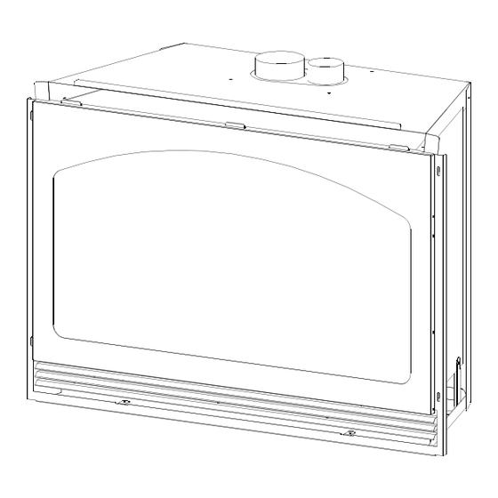
Page 5: Fireplace Insert Components
FIREPLACE COMPONENTS: Check the assembly diagram below to ensure you have all the necessary components to properly install this fireplace insert. This insert includes the following: 1. Fireplace Insert. 2. Spring-loaded latch glass assembly. 3. Millivolt board with burner cover. 4. -
Page 6: Preparing The Existing Fireplace
A) PREPARE THE EXISTING FIREPLACE WARNING: CUTTING ANY SHEET-METAL PARTS OF THE FIREPLACE, IN WHICH THIS GAS FIREPLACE INSERT IS TO BE INSTALLED, IS PROHIBITED. The refractory, glass doors, screen rails, screen mesh and log grates may be removed from the fireplace before installing this gas fireplace insert. - Page 7 Figure B-1 2. This fireplace insert is designed to accept either a 3/8" or 1/2" gas line approved for gas appliances. Consult local building codes to properly size the gas supply line leading to a 3/8" reduction. 3. Connect the manual shut off valve to the previous run gas line. 4.
-
Page 8: Insert Preparation
REMOVE THE FOLLOWING ITEMS FROM THE FIREPLACE INSERT: Figure C-1 1. GLASS ASSEMBLY: A) Locate the spring-loaded latches securing the glass assembly (under the firebox). B) While holding onto the glass frame, pull the latch handles out to release from the clips on the glass assembly. -
Page 9: Remove The Air Duct
3. REMOVE THE AIR DUCT. Figure C-4. A. Pull the lower end of the air duct out of the (4) mounting holes at the back and lift the air duct (manifold) up from the top of the firebox and set aside. Figure C-4 D. -
Page 10: Co-Linear Vent System
2. INSTALL THE VENT SYSTEM NOTE: The 4” exhaust pipe and 3” combustion air intake pipe will extend 25 ft. An optional extension kit (Part #510) is available to extend the #815-CL kit up to a maximum of 40 ft. A. -
Page 11: Install The Vent System
3. RUN THE VENT SYSTEM THROUGH THE EXISTING CHIMNEY ˆ OPTIONAL: We recommend wrapping the first 3 ft. of the vent system below the termination cap with non-faced fiberglass insulation (secure with wire) before running it through the existing chimney. This will prevent cold air from coming down the existing chimney. -
Page 12: Position The Insert & Secure The Air Duct
E. POSITION THE FIREPLACE INSERT: 1. Slide the insert in the fireplace opening. 2. If necessary, level the insert by threading the leveling bolts (included in the components packet) into the nuts mounted in the bottom of the insert behind the lower grill. See Figure E-1. -
Page 13: Replace The Millivolt Board
F. REINSTALL MILLIVOLT BOARD INSTALLATION. See Figures F-1 & F-2. NOTE: The millivolt board must be fitted with a gasket, (included) to seal the board. Make certain this gasket is properly placed around the opening before installing the millivolt board. 1. -
Page 14: Log Installation
LOG INSTALLATION. See Figures G-1 - G-3. This log set includes: (1) ‘S421’ log (1) ‘BC’ log (1) ‘BB’ log (1) XXL901 BOTTOM REFRACTORY PANELS (1) ‘S423’ log (1) ‘S424’ log (1) ‘AP1’ log (1) Embers pkg. (1) ‘BL’ log (1) ‘X5’... -
Page 15: Assemble & Attach The Shroud
H. ATTACH THE SHROUD Shroud assembly includes: (1) Shroud top (1) Set (1 left & 1 right) ‘inside fit’ brackets (1) Shroud left side (12) Phillips head screws (1) Shroud right side with on/off rocker switch mounting hole Additional items needed: Rocker switch &... - Page 16 CONNECT THE ROCKER SWITCH WIRES TO THE VALVE Refer to Figure N-1 page #24. 1. Slide the remaining connectors on the rocker switch wires to the top and bottom terminals marked ‘TH’ on the valve. IMPORTANT: CHECK ALL CONNECTIONS, WHETHER FIELD OR FACTORY MADE, FOR LEAKS. INSIDE FIT APPLICATIONS: NOTE: INSIDE FIT APPLICATIONS REQUIRE THE ‘INSIDE FIT MOUNTING BRACKETS’, INCLUDED WITH THIS KIT, FOR INSTALLATION.
- Page 17 Position the tabs (lower end previously cut), on the shroud, 2 each side, into the slots in the fireplace face and align the oblong holes on the left & right inside flange of the side shroud pieces to the holes in the mounting brackets. Secure with the remaining (4) screws (C), 2 each side.
-
Page 18: Complete The Fan Installation
COMPLETE THE FAN INSTALLATION: This insert comes complete with a fan, speed control and temperature limit switch assembly already installed. This fan is equipped with a three-prong (grounding) plug attached to the end of the 8 ft. fan electrical cord for protection against shock hazard and should be plugged directly into a properly grounded three-prong receptacle. -
Page 19: Complete The Installation
J. COMPLETE THE INSTALLATION THIS STEP SHOULD ONLY BE DONE BY A QUALIFIED INSTALLER OR SERVICE TECHNICIAN: A) Perform lighting and shutdown procedures as described on pages #19-20. This should be done prior to replacing the glass so that any necessary adjustments can be made and proper operation and log position is verified. 2. -
Page 20: Thermostat - Remote Control - Wall Switch Installation
K. THERMOSTAT - WALL SWITCH - REMOTE INSTALLATION (optional). CAUTION: DO NOT connect high voltage (115 V) wire to the switch. If desired, a thermostat (wireless available), wall switch or remote control assembly may be used to turn the fireplace ‘OFF’... -
Page 21: Lighting & Shutdown Procedures
L. LIGHTING & SHUTDOWN NOTE: Prior to lighting, check all fittings for leakage. This is accomplished by applying soapy water on all connections made. If there is any leakage, bubbles will appear at the point of connection. If bubbles occur, tighten the fittings until the bubbles no longer appear. - Page 22 Push in the black control knob all the way and hold in. Press the igniter button (B). The pilot will generally light with two or three pushes on the igniter. Hold the knob in for about one (1) minute after the pilot is lit.
-
Page 23: Manifold (Outgoing) & Inlet (Incoming) Pressure Check Procedures
PRESSURE TESTING MANIFOLD & INLET PRESSURE IMPORTANT NOTICE: A pressure check tap for both the manifold (outgoing) and inlet (incoming) pressure has been incorporated into the valve by Honeywell. The right pressure tap is the manifold pressure and the left pressure tap measures the incoming pressure. Follow the instructions below for proper pressure testing procedures. -
Page 24: Maintenance Requirements
M. MAINTENANCE REQUIREMENTS 1. The appliance should be inspected at least once a year MILLIVOLT BOARD SYSTEM by a professional service person. 1. Annual cleaning of the burner is required. The burner cover may be removed for easier access. Refer to Figure C-2, NOTE: INSTALLATION AND REPAIR SHOULD BE DONE page #6. -
Page 25: Troubleshooting
N) TROUBLE SHOOTING GUIDE NOTE: The millivolt board includes the following items: Regulator, generator, pilot, thermocouple, piezo, electrode, burner cover assembly, orifice and orifice holder. If any of these items are defective, contact your dealer for the appropriate repair / replacement procedures to follow. WARNING: DO NOT ATTEMPT TO SERVICE THIS FIREPLACE IF YOU ARE NOT A QUALIFIED SERVICE PERSON. - Page 26 PROBLEM CAUSE SOLUTION 4. Burner won't light. Pilot not lit. Relight pilot. Regulator valve not turned to ‘ON’. Turn valve to ‘ON’. Rocker switch not turned ‘ON’. Press the switch to the "ON" position. Rocker switch wires not connected. Check wiring diagram Figure N-1 and ensure that all wires are secure.
-
Page 27: Gas Conversion Kit
GAS CONVERSION KIT FOR MODEL #911-XXL DV I NSERT EQUIPPED WITH THE HONEYWELL GAS VALVE & PILOT ASSEMBLY THIS CONVERSION KIT SHALL BE INSTALLED BY A QUALIFIED SERVICE AGENCY IN ACCORDANCE WITH THE MANUFACTURER’S INSTRUCTIONS AND ALL APPLICABLE CODES AND REQUIREMENTS OF THE AUTHORITY HAVING JURISDICTION. IF THE INFORMATION IN THESE INSTRUCTIONS IS NOT FOLLOWED EXACTLY, A FIRE, EXPLOSION, OR PRODUCTION OF CARBON MONOXIDE MAY RESULT, CAUSING PROPERTY DAMAGE, PERSONAL INJURY OR LOSS OF LIFE. - Page 28 ADJUST THE BURNER VENTURI SETTING: An adjustable air shutter is located at the end the burner tube and must be adjusted to the gas type you are converting to. To adjust the venturi, loosen the screw (A) and adjust venturi opening to either the Natural Gas or LP Gas setting listed below.
-
Page 29: Replacement Parts
REPLACEMENT PARTS Replacement parts are available through your local dealer. Information on optional components not listed below, is also available through your dealer. MILLIVOLT BOARD AND PARTS XXL-800 Millivolt Board - Natural Gas 700213B 18” Flexible Gas line - Black (gas line connection ) XXL-801 Millivolt Board - LP Gas 700224... -
Page 30: Warranty Policy
Page 28... - Page 31 Page 29...
Need help?
Do you have a question about the 911-XXL and is the answer not in the manual?
Questions and answers