Table of Contents
Advertisement
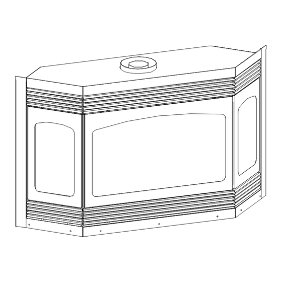
Model #961 DV
Installation & Operating
Instructions
This appliance may be installed in an aftermarket permanently located, manufactured home (USA
only) or mobile home, where not prohibited by local codes. This appliance is only for use with the
type(s) of gas indicated on the rating plate. This appliance is convertible for use with other gases.
An LP Gas conversion kit is included.
WARNING:
Improper installation, adjustment, alteration, service or maintenance can cause injury, property damage, or
loss of life. Refer to this manual for assistance. For additional information, consult a qualified installer, service
agency or the gas supplier.
READ ALL INSTRUCTIONS CAREFULLY BEFORE INSTALLATION. FAILURE TO
INSTALL THIS FIREPLACE CORRECTLY CAN CAUSE SERIOUS STRUCTURAL AND FIRE
IMPORTANT:
HAZARDS AND MAY VOID YOUR WARRANTY.
WARNING: If the information in these
instructions are not followed exactly, a fire
or explosion may result causing property
damage, personal injury or loss of life.
Do not store or use gasoline or other flammable
vapors and liquids in the vicinity of this or any
other appliance.
WHAT TO DO IF YOU SMELL GAS:
‚ Do not try to light any appliance.
‚ Do not touch electrical switches; do not use
the phone in your building.
‚ Immediately call your gas supplier from a
neighbor's phone. Follow the gas suppliers
instructions.
‚ If you cannot reach your gas supplier, call the
fire department.
‚ Installation and service must be performed by
a qualified installer, service agency or the gas
supplier.
February 2008
Advertisement
Table of Contents

Related Manuals for kozy heat 961 DV


Summary of Contents for kozy heat 961 DV
- Page 1 Model #961 DV WARNING: If the information in these instructions are not followed exactly, a fire Installation & Operating or explosion may result causing property damage, personal injury or loss of life. Instructions Do not store or use gasoline or other flammable vapors and liquids in the vicinity of this or any other appliance.
-
Page 2: Table Of Contents
Index DESCRIPTION PAGE Safety Requirements ..............2-3 Specifications . - Page 3 COMMONWEALTH OF MASSACHUSETTS REQUIREMENTS NOTE: The following requirements reference various Massachusetts and national codes not contained in this manual. For all sidewall horizontally vented gas fueled equipment installed in every dwelling, building or structure used in whole or in part for residential purposes, including those owned or operated by the Commonwealth and where the side wall exhaust vent termination is less than (7) feet above finished grade in the area of the venting , including but not limited to decks and porches, the following requirements shall be satisfied: INSTALLATION OF CARBON MONOXIDE DETECTORS...
- Page 4 COMMONWEALTH OF MASSACHUSETTS REQUIREMENTS MANUFACTURER REQUIREMENTS- GAS EQUIPMENT VENTING SYSTEM PROVIDED When the manufacturer of Product Approved side wall horizontally vented gas equipment provides a venting system de- sign or venting system components with the equipment, the instructions provided by the manufacturer for installation of the equipment and the venting system shall include: Detailed instructions for the installation of the venting system design or the venting system components;...
-
Page 5: Specifications
IMPORTANT READ THIS MANUAL BEFORE INSTALLING AND USING THIS FIREPLACE GAS FIREPLACE MODEL 961 DIRECT VENT INSTALLATION INSTRUCTIONS This appliance has been tested to & complies with ANSI Z21.88-2002·CSA 2.33-M02 ‘VENTED GAS FIREPLACE HEATER’. Installation must conform with local building codes, or, in the absence of local building codes, with the national fuel gas code, ANSI Z223.1- NFPA 54 (Current Edition). -
Page 6: Determine Location
Minimum clearance to combustibles: Top Stand-off: 0" From flue vent:: 1" Sides & Back: 0” Heat Outlet grill to mantel: (See Figure 2) Floor: 0" Bay Front to Adjacent Sidewall: 12” Side Glass to Adjacent Sidewall: 3” Mantel depth Figure 2 A) DETERMINE LOCATION. - Page 7 NOTE: DUE TO HIGH TEMPERATURES, THIS FIREPLACE SHOULD BE LOCATED OUT OF TRAFFIC AREAS AND AWAY FROM FURNITURE AND DRAPERIES. Figure 3A MODEL 961 DIRECT VENT 7 1 4 NOTE: Even though the minimum clearance from the back wall is 0", we recommend that you allow an expansion space of 1/4"...
-
Page 8: Rough Opening Dimensions
11. Rough in the wall enclosure (Figure 3C). Minimum rough opening dimensions are 52” w x 31 1/4" h. Depth is determined by your specific application. Build the hearth, if used, to the desired size and height. NOTE: A metal or wood panel extending the full width and depth of the fireplace (minimum size is 51 5/8” wide x 18 ½"... -
Page 9: Venting Requirements
Kozy Heat Direct Vent Kit #745 – for terminations of 4’ or less. Kozy Heat Direct Vent Kit #718 – for terminations of 8’ or less. Kozy Heat Direct Vent Extension Kit #746 – Used to extend the #745 kit or #718 kit an additional 6’. - Page 10 HORIZONTAL & VERTICAL VENTING CHART VERTICAL RISE 1'-5" HORIZONTAL RUN EXAMPLE 1: Horizontal runs up to 2 ft. must have a minimum vertical rise of 17”. EXAMPLE 2: If the horizontal run is 8 ft., the vertical rise required is 28”. EXAMPLE 3: If the horizontal run is 21 ft., the vertical rise required is 48”.
- Page 11 TERMINATION VENT CAP LOCATION: This gas appliance must not be connected to a chimney flue serving another type of appliance. GENERAL: Terminations against vinyl siding must use a vinyl siding protector. Follow instructions included. DO NOT RECESS TERMINATION KIT INTO OUTSIDE BUILDING MATERIALS - i.e.: brick, stone, etc.. If necessary, extend framing so that termination kit will be exposed once building materials are installed.
-
Page 12: Restrictor Installation
RESTRICTOR INSTALLATION The restrictor plate included in the fireplace components packet can be installed as either a large or small restrictor, depending on your Figure 6A specific venting configuration. Large Restrictor There are several factors which can affect proper draft of the vent system and the burner operation of a fireplace. - Page 13 INSTALLATION OF THE #700 SERIES HORIZONTAL DIRECT VENT TERMINATION KIT(S). NOTE: #700 Series vent kits must be supported every 3 ft. to maintain proper rise. The flex pipe is permanently attached to the exterior wall plate. Do not attach the #745 or #718 termination kit to the fireplace (or extension kit) until it has passed through the wall.
- Page 14 INSTALLATION OF THE SIMPSON DURA-VENT INSTALLATION FOR VERTICAL TERMINATIONS: NOTE: ADAPTOR REQUIRED - #923-C adaptor is required to adapt the flue collars on the fireplace to the Dura-Vent chimney system and is available from your dealer. Follow the installation instructions included with the #923-C adaptor AND chimney system. This chimney system may be purchased from your local dealer.
-
Page 15: Fan Installation
FAN INSTALLATION INSTALLATION OF THIS FAN SHOULD BE DONE ONLY BY A QUALIFIED INSTALLER. IMPORTANT: THE FAN IS EASIEST TO INSTALL BEFORE THE MILLIVOLT BOARD IS CONNECTED TO THE GAS LINE. IMPORTANT: IF THE LOWER GRILL HAS BEEN INSTALLED, IT MUST BE REMOVED TO PROPERLY INSTALL THIS FAN. - Page 16 INSTALLATION INSTRUCTIONS. REFER TO FIGURE 11B. Remove the center front lower grill, if installed. OPTIONAL: For easier installation, the fans may be separated by unplugging the three-prong plug from the receptacle in the right fan assembly. Lay the left fan (A) (without receptacle) on its back & slide through the lower grill opening on the right side of the valve.
- Page 17 E) RUN THE GAS LINE. CAUTION: Installation of the gas line must only be done by a qualified person in accordance with local building codes. GAS CONVERSIONS: This fireplace is manufactured for use with Natural Gas. An LP Gas conversion kit is included with this fireplace. Follow instructions included with this conversion kit.
-
Page 18: Millivolt Board Removal / Installation
2. This fireplace is designed to accept either a 3/8" or 1/2" gas line approved for gas appliances. Consult local building codes to properly size the gas supply line leading to a 3/8" reduction. 3. A gas line knockout is positioned on either side of the fireplace for gas line connection. 4. - Page 19 10. Remove the pilot shield and set aside. Figure 11B. 11. Loosen and remove the (8) 1/4" nuts securing the millivolt board and, while grasping the board, gently lift it off the (8) studs and remove from the firebox. Figure 11C. Figure 11C 1/4"...
- Page 20 EXTERNALLY ADJUSTABLE VENTURI. FIGURES 12A - 12C. An externally adjustable venturi has been incorporated into the millivolt board assembly for this fireplace. Follow the instructions below for proper operation and settings. CAUTION: THE SURFACES OF THIS FIREPLACE ARE HOT WHILE THE BURNER IS IN OPERATION. ALLOW THE FIREPLACE TO COOL PRIOR TO ADJUSTING THE VENTURI OR USE EXTREME CAUTION AND WEAR THE APPROPRIATE PROTECTION TO AVOID SERIOUS BURNS.
-
Page 21: Log Installation
LOG INSTALLATION. See Figures 13A – 13D. This #961-50B log set includes: (1) BW1-log (1) BW4-log (1) BW7-log (1)BW10-Log (1) BW2-log (1) BW5-log (1) BW8-log (1) BW3-log (1) BW6-log (1) BW9-log (1) Embers pkg. Position the base logs BW1, BW2, & BW3 onto the burner cover aligning the holes and/or notches in the bottom of the logs to the brackets in the burner cover. - Page 22 THERMOSTAT - WALL SWITCH - REMOTE CONTROL INSTALLATION CAUTION: DO NOT CONNECT HIGH VOLTAGE (115 V) WIRE TO THE SWITCH If desired, a thermostat, wall switch, or remote control assembly may be used to turn the fireplace ‘OFF’ and Thermostat Wiring Diagram ‘ON’.
-
Page 23: Complete The Installation
This trim is also used when the fireplace is installed in a Kozy Heat cabinet or surround. Attach the appropriate set for your application. -
Page 24: Season Heat Dump Adjustment
4. SEASONAL HEAT DUMP ADJUSTMENT: This fireplace has been manufactured with an adjustable heat dump outlet located at the top inside the firebox. This allows infinite control over the amount of heat emitted into the living area without affecting the flame height. INSTALLER: Please install this fireplace with the heat damper (dump) in the closed position. -
Page 25: Re-Install The Glass Assembly / Install The Grills
7. Install the grills. Upper grills – A. Line the rods of the grill up with the upper holes. B. Place the rods in the holes and push up until the bottoms of the rods clear the face. C. Place the bottom of the rod into the lower hole and release. The grill will set down into place. Lower grills - See Figure 18. -
Page 26: Lighting And Shutdown Procedures
LIGHTING AND SHUTDOWN PROCEDURES NOTE: Prior to lighting, check all fittings for leakage. This is accomplished by applying soapy water on all connections made. If there is any leakage, bubbles will appear at the point of connection. If bubbles occur, tighten the fittings until the bubbles no longer appear. - Page 27 11. NOTE: When the fireplace is initially lit, condensation will appear on the glass, this is normal in all gas fireplaces, and will disappear in one to three minutes. TO TURN THE BURNER OFF: To turn the burner ‘OFF’, depress the ON/OFF rocker switch to ‘OFF’, flip ‘off’ the wall switch, or adjust the setting on the thermostat or remote control.
- Page 28 PRESSURE TEST - MANIFOLD & INLET PRESSURE IMPORTANT NOTICE: A pressure check tap for both the manifold (outgoing) and inlet (incoming) pressure has been incorporated into the valve by S.I.T. Controls. The right pressure tap is the manifold pressure and the left pressure tap measures the incoming pressure. Follow the instructions below for proper pressure testing procedures.
- Page 29 L) MAINTENANCE REQUIREMENTS 1. The appliance should be inspected at least once a MILLIVOLT BOARD SYSTEM year by a professional service person. Annual cleaning of the burner is required. The burner NOTE: INSTALLATION AND REPAIR SHOULD BE DONE ONLY assembly may be removed for easier access. BY A QUALIFIED SERVICE PERSON.
-
Page 30: Troubleshooting
TROUBLE SHOOTING GUIDE NOTE: The millivolt board includes the following items: Valve, pilot assembly, pilot shield, piezo, electrode, on/off rocker switch, burner tube, & burner orifice. If any of these items are defective, contact your dealer for the appropriate repair / replacement procedures to follow. -
Page 31: Wiring Diagram
PROBLEM CAUSE SOLUTION Burner won't light. Pilot not lit. Relight pilot. Regulator valve not turned “ON”. Turn valve to "ON". Rocker switch not turned “ON”. Press bottom of switch. Rocker switch wires not connected. Check wiring diagram Figure 21 to ensure that all wires are secure. Generator wires loose at Reposition wire and tighten regulator terminals. -
Page 32: Replacement Parts
Replacement Parts Replacement parts are available through your local Kozy Heat dealer. Please contact them for availability and pricing. MILLIVOLT BOARD AND PARTS 961-E770 #961 Millivolt Board - Natural Gas 961-E771 #961 Millivolt Board - LP Gas 700-098 Pilot Hood... - Page 33 Page 29...
- Page 34 Page 30...
Need help?
Do you have a question about the 961 DV and is the answer not in the manual?
Questions and answers
We don’t have a plate with the serial number on it in our fireplace. It was here when we bought the house. Can you please help. It was made in 2003. Thank you!