Sign In
Upload
Download
Table of Contents
Contents
Add to my manuals
Delete from my manuals
Share
URL of this page:
HTML Link:
Bookmark this page
Add
Manual will be automatically added to "My Manuals"
Print this page
×
Bookmark added
×
Added to my manuals
Manuals
Brands
Owon Manuals
Test Equipment
PDS5022S
User manual
Owon PDS5022S User Manual
Pds series portable colour digital storage oscilloscope
Hide thumbs
Also See for PDS5022S
:
User manual
(70 pages)
1
2
3
Table Of Contents
4
5
6
7
8
9
10
11
12
13
14
15
16
17
18
19
20
21
22
23
24
25
26
27
28
29
30
31
32
33
34
35
36
37
38
39
40
41
42
43
44
45
46
47
48
49
50
51
52
53
54
55
56
57
58
59
60
61
62
63
64
65
66
67
68
69
70
71
72
73
74
75
76
77
78
79
80
81
82
83
84
85
86
87
88
89
90
91
92
93
page
of
93
Go
/
93
Contents
Table of Contents
Troubleshooting
Bookmarks
Table of Contents
Table of Contents
General Safety Information
Safety Notice
Safety Symbols
General Features of the the PDS Serial Oscilloscope
Junior User's Guidebook
Introduction to the Front Panel and the User's Interface of the PDS Series Oscilloscope
Check the Package Contents
To Perform the Function Inspection
To Perform the Probe Compensation
To Set the Probe Attenuation Coefficient
To Use the Probe Safely
To Perform Self-Calibration
Introduction to the Vertical System
Introduction to the Horizontal System
Introduction to the Trigger System
Advanced User's Guidebook
To Set the Vertical System
Perform Mathematical Manipulation Function
Using FFT Function
Application of VERTICAL POSITION and VOLTS/DIV Knobs
To Set the Horizontal System
Window Setting
To Set the Trigger System
Trigger Control
The Trigger Control of PDS5022S、PDS6042S、PDS6062S、PDS6062T
Video Trigger
The Trigger Control of PDS7062T、PDS7102T
Alternate Trigger
To Operate the Function Menu
To Perform Sampling Setup
To Set the Display System
To Save and Recall a Waveform
Save and Recall the Wave Form
To Perform the Auxiliary System Function Setting
To Perform the Automatic Measurement
To Perform the Cursor Measurement
Cursor Measurement
To Use Autoscale
To Use Executive Buttons
Quick Start Guide
Example 1: Measurement of Simple Signals
Example 2: Gain of the Amplifier in the Metering Circuit
Example 3: Capture the Single Signal
Example 4: Analyze the Details of a Signal
Example 5: Application of X-Y Function
Example 6: Video Signal Trigger
Troubleshooting
Appendix A: Technical Specifications
Appendix B: Package Contents
Appendix C: Maintenance, Cleaning and Repairing
Appendix D: Battery Using Guide
Advertisement
Quick Links
1
Table of Contents
2
General Features of the the Pds Serial Oscilloscope
3
Introduction to the Front Panel and the User's Interface of the Pds Series Oscilloscope
4
Appendix A: Technical Specifications
5
Appendix C: Maintenance, Cleaning and Repairing
Download this manual
PDS Series
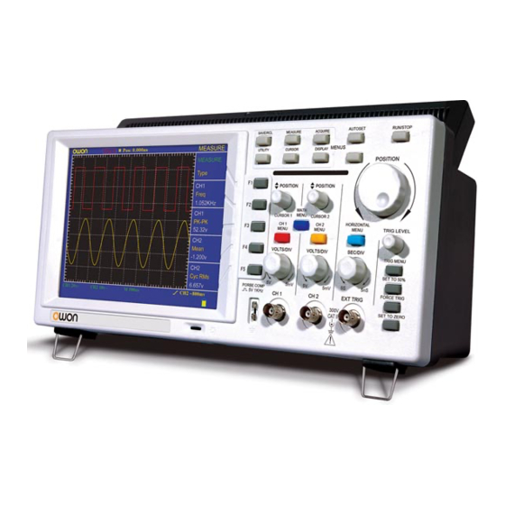
Portable Colour Digital Storage Oscilloscope
User Manual
■ PDS5022S
■ PDS6042S
■ PDS6062S
■ PDS6062T
■ PDS7062T
■ PDS7102T
WWW.OWON.COM.CN
Table of
Contents
Previous
Page
Next
Page
1
2
3
4
5
Advertisement
Table of Contents
Need help?
Do you have a question about the PDS5022S and is the answer not in the manual?
Ask a question
Questions and answers
Related Manuals for Owon PDS5022S
Test Equipment Owon PDS series User Manual
Pds series portable lcd digital storage oscilloscope (70 pages)
Test Equipment OWON PDS 6062T User Manual
Portable digital storage oscilloscope (80 pages)
Test Equipment Owon PDS8202T User Manual
Pds series portable mixed signal digital storage oscilloscope (86 pages)
Test Equipment Owon PDS8102T User Manual
Pds series portable mixed signal digital storage oscilloscope (86 pages)
Test Equipment Owon PDS6062S User Manual
Pds series portable colour digital storage oscilloscope (93 pages)
Test Equipment Owon PDS7102T User Manual
Pds series portable colour digital storage oscilloscope (93 pages)
Test Equipment Owon AG4151 User Manual
Arbitrary waveform generator (52 pages)
Test Equipment Owon MSO series User Manual
Portable mixed signal digital storage oscilloscope (108 pages)
Test Equipment Owon SDS series User Manual
Sds series smart digital storage oscilloscopes (98 pages)
Test Equipment Owon SDS5032E(V User Manual
Smart digital storage oscilloscopes (90 pages)
Test Equipment Owon tds series User Manual
Touchscreen digital storage oscilloscopes (82 pages)
Test Equipment Owon MSO5022 User Manual
Portable mixed signal digital storage oscilloscope (107 pages)
Test Equipment Owon SDS6062 User Manual
Sds series, smart digital storage (94 pages)
Test Equipment Owon SDS Series Service Manual
Smart digital storage oscilloscopes (44 pages)
Test Equipment Owon VDS6000 Series Quick Manual
(21 pages)
Test Equipment Owon VDS6000 Series User Manual
2ch pc oscilloscopes (64 pages)
This manual is also suitable for:
Pds6042s
Pds6062t
Pds7062t
Pds6062s
Pds7102t
Table of Contents
Save PDF
Print
Rename the bookmark
Delete bookmark?
Delete from my manuals?
Login
Sign In
OR
Sign in with Facebook
Sign in with Google
Upload manual
Upload from disk
Upload from URL


Need help?
Do you have a question about the PDS5022S and is the answer not in the manual?
Questions and answers