
Subscribe to Our Youtube Channel
Related Manuals for Owon PDS 6062T


Summary of Contents for Owon PDS 6062T
- Page 1 User’s Manual of OWON Colour Digital Storage Oscilloscope OWON PDS 6062T Portable Digital Storage Oscilloscope User's Manual WWW.OWON.COM.CN...
- Page 2 The information in this manual will replace all that in the materials published originally. Reserved will be the rights to change product specifications and prices. Lilliput Company, the 5 floor, B Area, Chuangxin Mansion, Xiamen Software Zone. OWON is the registered trademark of the Lilliput Company.
- Page 3 User’s Manual of OWON Colour Digital Storage Oscilloscope Warranty Summary (PDS Series Digital Storage Oscilloscope) The Lilliput guarantees that no faults in material and processing will present in the products produced and sold by the company within 3 years since the date when they are delivered by the authorized retail trader of Lilliput.
- Page 4 User’s Manual of OWON Colour Digital Storage Oscilloscope Warranty Summary (Probe) The Lilliput guarantees that no faults in material and processing will emerge in the products produced and sold by the company within one year since the date when they are delivered.
-
Page 5: Table Of Contents
User’s Manual of OWON Colour Digital Storage Oscilloscope Table of Contents General Safety Requirements....................7 Safety Terms and Symbols....................8 General Characteristics of the PDS6062T Colour Digital Storage Oscilloscope.... 10 Junior User’s' Guidebook ....................11 Introduction to the Front Panel and the User's Interface of the PDS series Oscilloscope .. 12 How to Carry on the General Inspection ................ - Page 6 User’s Manual of OWON Colour Digital Storage Oscilloscope How to Save and Recall a Wave Form..................53 Save and Recall the Wave Form....................54 How to Carry on the Auxiliary System Function Setting ............55 Do Self Cal (Self-Calibration)....................56 SYS STAT (System State)......................
-
Page 7: General Safety Requirements
User’s Manual of OWON Colour Digital Storage Oscilloscope General Safety Requirements Before any operations, please read the following safety precautions to avoid any possible bodily injury and prevent this product or any other products connected from damage. In order to avoid any contingent danger, this product is only used within the range specified. -
Page 8: Safety Terms And Symbols
User’s Manual of OWON Colour Digital Storage Oscilloscope Safety Terms and Symbols Terms in this manual. The following terms may appear in this manual: Warning. A warning statement indicates the conditions and actions which may endanger the life safety. Note. A note statement indicates the conditions and actions which may cause damage to this product or other property. - Page 9 User’s Manual of OWON Colour Digital Storage Oscilloscope To avoid body damage and prevent product and connected equipment damage. This product can only be used in the specified applications. Carefully read the following safety information before using the test tool.
-
Page 10: General Characteristics Of The Pds6062T Colour Digital Storage Oscilloscope
User’s Manual of OWON Colour Digital Storage Oscilloscope General Characteristics of the PDS6062T Colour Digital Storage Oscilloscope With the bandwidth of 60M; Record length of 5,000 points for each channel; Sampling rates of 250MS/s for each channel; Reading-out with the cursor;... -
Page 11: Junior User's' Guidebook
User’s Manual of OWON Colour Digital Storage Oscilloscope Junior User’s' Guidebook This chapter deals with the following topics mainly: Introduction to the front panel and the user’s interface of the PDS series oscilloscope How to carry on the general inspection... -
Page 12: Introduction To The Front Panel And The User's Interface Of The Pds Series Oscilloscope
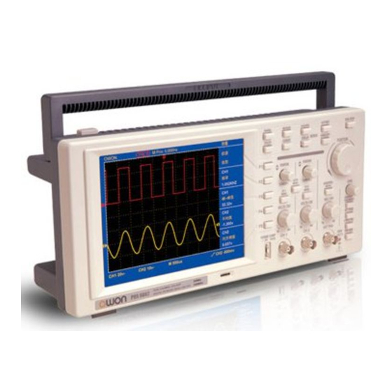
User’s Manual of OWON Colour Digital Storage Oscilloscope Introduction to the Front Panel and the User's Interface of the PDS series Oscilloscope When you get a new-type oscilloscope, you should get acquainted with its front panel at first and the PDS series digital storage oscilloscope is no exception. This chapter... - Page 13 User’s Manual of OWON Colour Digital Storage Oscilloscope Fig. 1 The Front Panel of a PDS series Oscilloscope Function Buttons Adjustment Horizontal Trigger Back-light Vertical Control Connector Menu Selection Control Control Fig. 2 Explanatory Drawing for Operations of the PDS series Oscilloscope...
- Page 14 User’s Manual of OWON Colour Digital Storage Oscilloscope Fig. 3 Illustrative Drawing of Display Interfaces 1. The Trigger State indicates the following information: Auto: The oscilloscope is under the Automatic mode and is collecting the waveform under the non-trigger state.
- Page 15 User’s Manual of OWON Colour Digital Storage Oscilloscope 7. It indicates the operation options for the current function menu, which changes with the function menus. 8. The purple pointer shows the trigger level position. 9. The reading shows the trigger level value.
-
Page 16: How To Carry On The General Inspection
User’s Manual of OWON Colour Digital Storage Oscilloscope How to Carry on the General Inspection After you get a new PDS series oscilloscope, it is recommended that you should make a check on the instrument according to the following steps: 1. -
Page 17: How To Carry On The Function Inspection
User’s Manual of OWON Colour Digital Storage Oscilloscope How to Carry on the Function Inspection Make a fast function check to verify the normal operation of the instrument, according to the following steps: 1. Connect the Instrument to the Power and Push down the Power Switch Button. - Page 18 User’s Manual of OWON Colour Digital Storage Oscilloscope Probe comp Fig. 5 Connection of the Probe 3. Press the AUTOSET Button. The square wave of 1 KHz frequency and 5V peak-peak value will be displayed in several seconds (see Fig. 6).
-
Page 19: How To Implement The Probe Compensation
User’s Manual of OWON Colour Digital Storage Oscilloscope How to Implement the Probe Compensation When connect the probe with any input channel for the first time, make this adjustment to match the probe with the input channel. The probe which is not compensated or presents a compensation deviation will result in the measuring error or mistake. -
Page 20: How To Set The Probe Attenuation Coefficient
User’s Manual of OWON Colour Digital Storage Oscilloscope How to Set the Probe Attenuation Coefficient The probe has several attenuation coefficients, which will influence the vertical scale factor of the oscilloscope. If it is required to change (check) the set value of the probe attenuation coefficient, press the function menu button of the channels used, then push down the selection button corresponding to the probe till the correct set value is shown. -
Page 21: How To Use The Probe Safely
User’s Manual of OWON Colour Digital Storage Oscilloscope How to Use the Probe Safely The safety guard ring around the probe body protects your finger against the electric shock, shown as Fig. 10. Fig. 10 Finger Guard Warning: In order to avoid suffering from the electric shock, please keep your finger behind the safety guard ring of the probe body during the operation. -
Page 22: How To Implement Auto-Calibration
User’s Manual of OWON Colour Digital Storage Oscilloscope How to Implement Auto-calibration The auto-calibration application can make the oscilloscope reach the optimum condition rapidly to obtain the most accurate measurement value. You can carry out this application program at any time, but when the range of variation of the ambient temperature is up to or over 5℃, this program must be executed. -
Page 23: Introduction To The Vertical System
User’s Manual of OWON Colour Digital Storage Oscilloscope Introduction to the Vertical System Shown as Fig.11, there are a series of buttons and knobs in VERTICAL CONTROLS. The following practices will gradually direct you to be familiar with the using of the vertical setting. -
Page 24: Introduction To The Horizontal System
User’s Manual of OWON Colour Digital Storage Oscilloscope Introduction to the Horizontal System Shown as Fig.12, there are a button and two knobs in the “HORIZONTAL CONTROLS”. The following practices will gradually direct you to be familiar with the setting of horizontal time base. -
Page 25: Introduction To The Trigger System
User’s Manual of OWON Colour Digital Storage Oscilloscope Introduction to the Trigger System Shown as Fig.13, there are a knob and four buttons in the “TRIGGER CONTROLS”. The following practices will direct you to be familiar with the setting of the trigger system gradually. -
Page 26: Advanced User's Guidebook
User’s Manual of OWON Colour Digital Storage Oscilloscope Advanced User's Guidebook Up till now, you have already been familiar with the initial operations of “VERTICAL CONTROLS”, “HORIZONTAL CONTROLS” and “TRIGGER CONTROLS”, and the functions of the function areas, buttons and knobs in the front panel of the PDS series oscilloscope. -
Page 27: How To Set The Vertical System
User’s Manual of OWON Colour Digital Storage Oscilloscope How to Set the Vertical System The VERTICAL CONTROLS includes three menu buttons such as CH1 MENU, CH2 MENU and MATH MENU, and four knobs such as VERTICA POSITION, VOLTS/DIV (one group for each of the two channels). - Page 28 User’s Manual of OWON Colour Digital Storage Oscilloscope The description of the Channel Menu is shown as the following list: following form: Function Menu Setting Description Coupling Block the AC component in the input signal. Unblock the AC and DC components in the input signal.
- Page 29 User’s Manual of OWON Colour Digital Storage Oscilloscope Fig. 15 AC Coupling Oscillogram Fig. 16 DC Coupling Oscillogram...
- Page 30 User’s Manual of OWON Colour Digital Storage Oscilloscope Setting the Channel “ON/OFF” Taking the Channel 1 for example, the operation steps are shown as below: (1). Press the CH1 MENU button and call out the CH1 SETUP menu. (2). Press the F2 menu selection button and select the Channel as OFF, with Channel 1 switched off.
- Page 31 User’s Manual of OWON Colour Digital Storage Oscilloscope A List of the Attenuation Coefficients of Probes and the Corresponding Menu Settings. Attenuation Coefficient of the Probe Corresponding Menu Setting 10:1 100:1 100X 1000:1 1000X Setting of Wave Form Inverted Wave form inverted: the displayed signal is turned 180 degrees against the phase of the earth potential.
- Page 32 User’s Manual of OWON Colour Digital Storage Oscilloscope Fig. 18 Wave Form not Inverted Fig. 19 Wave Form Inverted...
-
Page 33: Implementation Of Mathematical Manipulation Function
User’s Manual of OWON Colour Digital Storage Oscilloscope Implementation of Mathematical Manipulation Function The Mathematical Manipulation function is used to show the results of the additive and subtraction operations between Channel 1 and Channel 2. Taking the additive operation between Channel 1 and Channels 2 for example, the operation steps are as follows: 1. -
Page 34: Application Of Vertical Position And Volts/Div Knobs
User’s Manual of OWON Colour Digital Storage Oscilloscope Application of VERTICAL POSITION and VOLTS/DIV Knobs 1. The .VERTIVAL POSITION knob is used to adjust the vertical positions of the wave forms of all Channels (including those resulted from the mathematical operation). -
Page 35: How To Set The Horizontal System
User’s Manual of OWON Colour Digital Storage Oscilloscope How to Set the Horizontal system The HORIZONTAL CONTROLS includes the HORIZONTAL NENU button and such knobs as HORIZONTAL POSITION and SEC/DIV. 1. HORIZONTAL POSITION knob: this knob is used to adjust the horizontal positions of all channels (include those obtained from the mathematical manipulation), the analytic resolution of which changes with the time base. -
Page 36: Main Time Base
User’s Manual of OWON Colour Digital Storage Oscilloscope Main Time Base Press the F1 menu selection button and choose the Main Time Base. In this case, the HORIZONTAL POSITION and SEC/DIV knobs are used to adjust the main window. The display in the screen is shown as Fig. 23. -
Page 37: Window Setting
User’s Manual of OWON Colour Digital Storage Oscilloscope Window Setting Press the F2 menu selection button and choose Set Window. The screen will show a window area defined by two cursors. In this case, the HORIZONTAL POSITION and SEC/DIV knobs can be used to adjust the horizontal position and size of this window area (see Fig. -
Page 38: Window Expansion
User’s Manual of OWON Colour Digital Storage Oscilloscope Window Expansion Press the F3 menu selection button and choose Zone Window. As a result, the window area defined by two cursors will be expanded to the full screen size (see Fig. -
Page 39: How To Set The Trigger System
User’s Manual of OWON Colour Digital Storage Oscilloscope How to Set the Trigger System When the oscilloscope begins to collect the data and display the wave form depends on a trigger. Once it is set correctly, the trigger can transfer the unstable display into a meaningful wave form. -
Page 40: Trigger Control
User’s Manual of OWON Colour Digital Storage Oscilloscope Trigger Control There are two trigger modes: Edge Trigger and Video Trigger. Each trigger mode uses different function menu. The switching between two modes can be implemented by pressing the F1 menu selection button. - Page 41 User’s Manual of OWON Colour Digital Storage Oscilloscope The Edge Trigger Menu is described as below: Function Menu Setting Description Slope Rising Set a trigger on the rising edge of the signal. Falling Set a trigger on the falling edge of the signal.
- Page 42 User’s Manual of OWON Colour Digital Storage Oscilloscope Fig. 28 Wave Form Triggered on the Rising Edge Fig. 29 Wave Form Triggered on the Falling Edge...
-
Page 43: Video Trigger
User’s Manual of OWON Colour Digital Storage Oscilloscope Video Trigger After choosing “Video Trigger”, a trigger is possible in field or line of NTSC, PAL or SECAM standard video signal. The operation menu of Video Trigger is shown as Fig. 30. - Page 44 User’s Manual of OWON Colour Digital Storage Oscilloscope The operation steps for setting Channel 1 in Video Trigger Mode are as below: 1. Press the TRIG MENU button and get access to the trigger menu. 2. Press the F1 menu selection button and choose Video for Type.
- Page 45 User’s Manual of OWON Colour Digital Storage Oscilloscope Fig. 31 Wave Form Triggered in the Video Field Fig. 32 Wave Form Triggered in the Video Line...
-
Page 46: How To Operate The Function Menu
User’s Manual of OWON Colour Digital Storage Oscilloscope How to Operate the Function Menu The function menu control zone includes 6 function menu buttons and 3 immediate-execution buttons: SAVE/REL, MEASURE, ACQUIRE, UTILITY, CURSOR, DISPLAY, AUTOSET, RUN/STOP and HARDCOPY. How to Implement Sampling Setup Press the ACQUIRE button and the menu is displayed in the screen, shown as Fig. - Page 47 User’s Manual of OWON Colour Digital Storage Oscilloscope Change the ACQU Mode settings and observe the consequent variation of the wave form displayed. Fig. 34 Peak Detect mode, under which the burrs on the falling edge of the square wave,...
- Page 48 User’s Manual of OWON Colour Digital Storage Oscilloscope Fig. 35 Common ACQU Mode display, in which no burr can be detected. Fig. 36 The displayed wave form after the noise is removed under the Average Mode, in which the average number of 64 is set.
-
Page 49: How To Set The Display System
User’s Manual of OWON Colour Digital Storage Oscilloscope How to Set the Display System Push down the DISPLAY button and the menu displayed in the screen is shown as Fig. 37. Fig. 37 Display Set Menu The description of the Display Set Menu is shown as follows:... - Page 50 User’s Manual of OWON Colour Digital Storage Oscilloscope Display Type: With the F1 menu selection button pushed down, you can shift between Vectors and Dots types. The differences between the two display types can be observed through the comparison between Fig. 38 and Fig.39.
-
Page 51: Persist
User’s Manual of OWON Colour Digital Storage Oscilloscope Persist When the Persist function is used, the persistence display effect of the picture tube oscilloscope can be simulated: the reserved original data is displayed in fade color and the new data is in bright color. With the F2 menu selection button, different persistence time can be chosen: 1sec, 2sec, 5sec, Infinite and Closed. - Page 52 User’s Manual of OWON Colour Digital Storage Oscilloscope The following functions can not work in the XY Format: Reference or digital wave form Cursor Auto Set Time base control Trigger control Operation steps: 1. Press the DISPLAY button and call out the Display Set Menu.
-
Page 53: How To Save And Recall A Wave Form
User’s Manual of OWON Colour Digital Storage Oscilloscope How to Save and Recall a Wave Form Press the SAVE/REL button, you can save and call out the wave forms in the instrument. The menu displayed in the screen is shown as Fig. 42. -
Page 54: Save And Recall The Wave Form
User’s Manual of OWON Colour Digital Storage Oscilloscope Save and Recall the Wave Form The PDS series oscilloscope can store four wave forms, which can be displayed with the current wave form at the same time. The stored wave form called out can not be adjusted. -
Page 55: How To Carry On The Auxiliary System Function Setting
User’s Manual of OWON Colour Digital Storage Oscilloscope How to Carry on the Auxiliary System Function Setting Press the UNTILITY button and the menu is displayed in the screen as Fig. 45. Fig. 45 Function Menu The description of the Auxiliary Function Menu is shown as the following table. -
Page 56: Do Self Cal (Self-Calibration)
User’s Manual of OWON Colour Digital Storage Oscilloscope Do Self Cal (Self-Calibration) The self-calibration procedure can improve the accuracy of the oscilloscope under the ambient temperature to the greatest extent. If the change of the ambient temperature is up to or exceeds 5℃, the self-calibration procedure should be executed to obtain the highest level of accuracy. - Page 57 User’s Manual of OWON Colour Digital Storage Oscilloscope The “SYS STAT” menu is described as the following table: Function Menu Setting Description Horizontal Show the horizontal parameter of the channel. Vertical Show the vertical parameter of the channel. Trigger Show the parameters of the trigger system.
-
Page 58: How To Conduct The Automatic Measurement
User’s Manual of OWON Colour Digital Storage Oscilloscope How to Conduct the Automatic Measurement With the Measure button pressed down, an automatic measurement can be implemented. There are 5 types of measurements and 4 measurement results can be displayed simultaneously. - Page 59 User’s Manual of OWON Colour Digital Storage Oscilloscope RMS of the Channel CH2, according the following steps: 1. Press the F1 menu selection button and choose Source. 2. Press the F2 menu selection button and choose CH1. 3. Press the F3 menu selection button and choose CH1.
-
Page 60: How To Carry On The Cursor Measurement
User’s Manual of OWON Colour Digital Storage Oscilloscope How to Carry on the Cursor Measurement Press the CURSOR button to display the cursor measurement function menu (CURS MEAS) in the screen, which includes Voltage Measurement and Time Measurement, shown as Fig. 50. -
Page 61: Cursor Measurement
User’s Manual of OWON Colour Digital Storage Oscilloscope Cursor Measurement When carrying out the cursor measurement, the position of Cursor 1 can be adjusted with the CURSOR1 (VERTICAL POSITION) knob of Channel 1, and that of Cursor 2 can be adjusted with the CURSOR2 (VERTICAL POSITION) knob of Channel 2. - Page 62 User’s Manual of OWON Colour Digital Storage Oscilloscope Carry out the following operation steps for the time cursor measurement of the channel CH1: 1. Press “CURSOR” and recall the CURS MEAS menu. 2. Press the F1 menu selection button and choose Time for Type, with two purple dotted lines displayed along the vertical direction of the screen, which indicating Cursor 1 and Cursor 2.
-
Page 63: How To Use Executive Buttons
User’s Manual of OWON Colour Digital Storage Oscilloscope How to Use Executive Buttons The executive buttons include AUTOSET, RUN/STOP and HARDCOPY. AUTOSET This button is used for the automatic setting of all control values of the instrument to generate the wave form suitable for observation. Press the AUTOSET button and the oscilloscope will perform the fast automatic measurement of the signal. -
Page 64: Examples Of Application
User’s Manual of OWON Colour Digital Storage Oscilloscope Examples of Application Example 1: Measurement of Simple Signals Observe an unknown signal in the circuit, and display and measure rapidly the frequency and peak-to-peak value of the signal. Carry out the following operation steps for the rapid display of this signal: 1. -
Page 65: Example 2: Gain Of The Amplifier In The Metering Circuit
User’s Manual of OWON Colour Digital Storage Oscilloscope Fig. 53 Waveform of Automation Measurement Example 2: Gain of the Amplifier in the Metering Circuit Set the probe menu attenuation coefficient as 10X and that of the switch in the probe as 10X. -
Page 66: Example 3: Capture The Single Signal
User’s Manual of OWON Colour Digital Storage Oscilloscope 8. Press the F3 menu selection button and choose Pk-Pk. 10. Read the peak-to-peak values of Channel 1 and Channel 2 from the displayed menu (see Fig. 54). 11. Calculate the amplifier gain with the following formulas. - Page 67 User’s Manual of OWON Colour Digital Storage Oscilloscope edge trigger. If it is uncertain as to the signal, you can make an observation of it in advance under the automatic or ordinary mode to determine the trigger level and the trigger edge.
-
Page 68: Example 4: Analyze The Details Of A Signal
User’s Manual of OWON Colour Digital Storage Oscilloscope Fig. 55 Capture the Single Signal Example 4: Analyze the Details of a Signal Observe the Signal Containing Noises If the signal is interfered by the noise, the noise may cause a failure in the circuit. For... - Page 69 User’s Manual of OWON Colour Digital Storage Oscilloscope Fig. 56 Wave Form of the Signal Containing Noises Separate Noises from the Signal When analyze the wave form of a signal, you should remove the noise contained in it. For the reduction of the random noise in the oscilloscope display, please operate the instrument according to the following step: 1.
-
Page 70: Example 5: Application Of X-Y Function
User’s Manual of OWON Colour Digital Storage Oscilloscope Fig. 57 Wave Form of the Noise-Removed Signal Example 5: Application of X-Y Function Examine the Phase Difference between Signals of two Channels Example: Test the phase change of the signal after it passes through a circuit network. -
Page 71: Example 6: Video Signal Trigger
User’s Manual of OWON Colour Digital Storage Oscilloscope 6. Push down the DISPLAY button and recall the DISP SET menu. 7. Press the F3 menu selection button and choose XY for Format. The oscilloscope will display the input and terminal characteristics of the network in the Lissajous graph form. - Page 72 User’s Manual of OWON Colour Digital Storage Oscilloscope video output signal display. Video Field Trigger For the trigger in the video field, carry out operations according to the following steps: 1. Press the TRIG MENU button to display the trigger menu.
- Page 73 User’s Manual of OWON Colour Digital Storage Oscilloscope 4. Press the F3 menu selection button and choose CH1 for Source. 5. Press the F4 menu selection button and choose Line for Sync. 6. Adjust the VOLTS/DIV, VERTICAL POSITION and SEC/DIV knobs to obtain the proper wave form display (see Fig.
-
Page 74: Fault Treatment
User’s Manual of OWON Colour Digital Storage Oscilloscope Fault Treatment 1. In the case of that the oscilloscope is still in the black-screen state without any display after the power is switch on, implement the following fault treatment procedure. Check whether the power connection is connected properly. -
Page 75: Appendix A: Technical Specifications
User’s Manual of OWON Colour Digital Storage Oscilloscope Appendix A: Technical Specifications Unless otherwise specified, the technical specifications applied are applicable to the probe with the attenuation switch setting 10X and the PDS series digital oscilloscope. Only if the oscilloscope fulfill the following two conditions at first, can these specification standards be reached. - Page 76 User’s Manual of OWON Colour Digital Storage Oscilloscope Vertical A/D Converter Resolution of 8 bits, with the sampling carried out in two channels at the same time. Sensitivity (Volt/division) 5mV/div- 5V/div (at the input BNC) Range (V/div ) Displacement Range ±...
- Page 77 User’s Manual of OWON Colour Digital Storage Oscilloscope Trigger Trigger Sensitivity DC Coupling Channel 1 and Channel 2: 1div (DC ~ (Edge Trigger) Full Bandwidth ) 100mV(DC- 20M) EXT/5 500mV(DC- 20M) AC Coupling It is the same as the DC coupling in case of 50Hz or more.
- Page 78 User’s Manual of OWON Colour Digital Storage Oscilloscope General Technical Specifications Display Display Type 8"TFT LCD (Liquid Crystal Display) Display Resolution 640 (Horizontal) × 480 (Vertical) Pixels Display Colors 260000 Colors Output of the Probe Compensator Output Voltage About 5V, with the Peak-to-Peak value equal to or greater (Typical ) than 1MΩ...
-
Page 79: Appendix B: Enclosure
User’s Manual of OWON Colour Digital Storage Oscilloscope Appendix B: Enclosure Standard Accessories: Passive probe: 2, 1.2 m, 1:1 (10:1) CD: 1, for operation instruction. RS232 data line or USB data line Power line: one, up to the standards of the country in which it is used. -
Page 80: Appendix D: Battery Using Guide
User’s Manual of OWON Colour Digital Storage Oscilloscope Appendix D: Battery Using Guide Charging the oscilloscope The lithium battery maybe not be charged when delivery. Please charge the battery for 12 hours to make sure enough power to supply (the oscilloscope should be turned on during charging) to oscilloscope.
Need help?
Do you have a question about the PDS 6062T and is the answer not in the manual?
Questions and answers