
Subscribe to Our Youtube Channel
Related Manuals for Owon PDS series


Summary of Contents for Owon PDS series
- Page 1 PDS Series Portable LCD Digital Storage Oscilloscope User Manual ■PDS5022S ■PDS5022T ■PDS6042S ■PDS6062S www.owon.com.cn www.owon.com.hk...
- Page 2 The information in this manual was correct at the time of printing. However, OWON will continue to improve products and reserves the rights to changes specification at any time without notice.
- Page 3 User Manual of PDS Series Oscilloscope General Warranty The Lilliput warrants that the product will be free from defects in materials and workmanship for a period of three years from the date of purchase of the product by the original purchaser from the Lilliput company. And the warranty period of accessories such as probe, battery, adapter is one year.
-
Page 4: Table Of Contents
User Manual of PDS Series Oscilloscope Table of Contents General Safety Information ....................4 Safety Terms and Symbols....................5 General features ........................7 Junior User's Guidebook..................... 8 Introduction to the Front Panel and the User's Interface of the PDS series Oscilloscope ..9 Check the Package Contents .................... - Page 5 User Manual of PDS Series Oscilloscope To set the Display System......................40 To Save and Recall a Waveform....................42 To perform the Auxiliary System Function Setting..............44 To perform the Automatic Measurement ................46 To perform the Cursor Measurement..................49 Use Autoscale ..........................
-
Page 6: General Safety Information
User Manual of PDS Series Oscilloscope General Safety Information Before any operations, please read the following safety precautions to avoid any possible bodily injury and prevent this product or any other products connected from damage. In order to avoid any contingent danger, this product is only used within the range specified. -
Page 7: Safety Terms And Symbols
User Manual of PDS Series Oscilloscope Safety Terms and Symbols Safety Terms Terms in this manual. The following terms may appear in this manual: Warning: Warning indicates the conditions or practices that could result in injury or loss of life. Caution: Caution indicates the conditions or practices that could result in damage to this product or other property. - Page 8 User Manual of PDS Series Oscilloscope To avoid body damage and prevent product and connected equipment damage, carefully read the following safety information before using the test tool. This product can only be used in the specified applications. Warning The two channels of the oscilloscope are non-isolated electrically. The channels should adopt common basis during measuring.
-
Page 9: General Features
User Manual of PDS Series Oscilloscope General features Model Bandwidth Sample Rate PDS5022S/T 25MHz 100MS/s PDS6042S 40MHz 250MS/s PDS6062S 60MHz 250MS/s Record length of 6,000 points for each channel; Reading-out with the cursor; Twenty automatic measurement functions; Autoscale function; Color liquid crystal display of high resolution and high contrast; Storage and recall waveforms;... -
Page 10: Junior User's Guidebook
User Manual of PDS Series Oscilloscope Junior User's Guidebook This chapter deals with the following topics mainly: Introduction to the front panel and the user’s interface of the PDS series oscilloscope To perform the general inspection To perform the function inspection To perform the probe compensation To set the probe attenuation coefficient To use the probe safely... -
Page 11: Introduction To The Front Panel And The User's Interface Of The Pds Series Oscilloscope
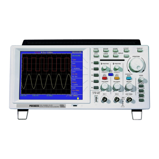
User Manual of PDS Series Oscilloscope Introduction to the Front Panel and the User's Interface of the PDS series Oscilloscope When you get a new-type oscilloscope, you should get acquainted with its front panel at first and the PDS series digital storage oscilloscope is no exception. This chapter makes a simple description of the operation and function of the front panel of the PDS series oscilloscope, enabling you to be familiar with the use of the PDS series oscilloscope in the shortest time. - Page 12 User Manual of PDS Series Oscilloscope Fig.1 The Front Panel of a PDS series Oscilloscope Function Buttons Adjustment Horizontal Trigger Vertical Control Connector Menu Selection Control Control Fig.2 Explanatory Drawing for Operations of the PDS series Oscilloscope...
- Page 13 User Manual of PDS Series Oscilloscope Fig.3 Illustrative Drawing of Display Interfaces 1. The Trigger State indicates the following information: Auto: The oscilloscope is under the Automatic mode and is collecting the waveform under the non-trigger state. Trig’d: The oscilloscope has already detected a trigger signal and is collecting the after-triggering information.
- Page 14 User Manual of PDS Series Oscilloscope with the function menus. 8. The purple pointer shows the trigger level position. 9. The reading shows the trigger level value. 10. The reading shows the trigger source. 11. It shows the selected trigger type: Rising edge triggering Falling edge triggering Video line synchronous triggering...
-
Page 15: Check The Package Contents
User Manual of PDS Series Oscilloscope Check the Package Contents After you get a new PDS series oscilloscope, it is recommended that you should make a check on the instrument according to the following steps: 1. Check whether there is any damage caused by transportation. If it is found that the packaging carton or the foamed plastic protection cushion has suffered serious damage, do not throw it away first till the complete device and its accessories succeed in the electrical and mechanical property tests. -
Page 16: To Perform The Function Inspection
User Manual of PDS Series Oscilloscope To perform the Function Inspection Make a fast function check to verify the normal operation of the instrument, according to the following steps: 1. Connect the Instrument to the Power and Push down the Power Switch Button. The instrument carries out all self-check items and shows the prompt “Press any Key Enter the Operating Mode”. - Page 17 User Manual of PDS Series Oscilloscope Probe comp Fig.5 Connection of the Probe 3. Press the AUTO SET Button. The square wave of 1 KHz frequency and 5V peak-peak value will be displayed in several seconds (see Fig.6). Fig.6 Auto set Check CH2 by repeating Step 2 and Step 3.
-
Page 18: To Perform The Probe Compensation
User Manual of PDS Series Oscilloscope To perform the Probe Compensation When connect the probe with any input channel for the first time, make this adjustment to match the probe with the input channel. The probe which is not compensated or presents a compensation deviation will result in the measuring error or mistake. -
Page 19: To Set The Probe Attenuation Coefficient
User Manual of PDS Series Oscilloscope To set the Probe Attenuation Coefficient The probe has several attenuation coefficients, which will influence the vertical scale factor of the oscilloscope. If it is required to change (check) the set value of the probe attenuation coefficient, press the function menu button of the channels used, then push down the selection button corresponding to the probe till the correct set value is shown. -
Page 20: To Use The Probe Safely
User Manual of PDS Series Oscilloscope To use the Probe Safely The safety guard ring around the probe body protects your finger against the electric shock, shown as Fig.10. Fig.10 Finger Guard Warning: In order to avoid suffering from the electric shock, please keep your finger behind the safety guard ring of the probe body during the operation. -
Page 21: Introduction To The Vertical System
User Manual of PDS Series Oscilloscope Introduction to the Vertical System Shown as Fig.11, there are a series of buttons and knobs in VERTICAL CONTROLS. The following practices will gradually direct you to be familiar with the using of the vertical setting. Fig.11 Vertical Control Zone 1. -
Page 22: Introduction To The Horizontal System
User Manual of PDS Series Oscilloscope Introduction to the Horizontal System Shown as Fig.12, there are a button and two knobs in the “HORIZONTAL CONTROLS”. The following practices will gradually direct you to be familiar with the setting of horizontal time base. Fig.12 Horizontal Control Zone 1. -
Page 23: Introduction To The Trigger System
User Manual of PDS Series Oscilloscope Introduction to the Trigger System Shown as Fig.13, there are a knob and four buttons in the “TRIGGER CONTROLS”. The following practices will direct you to be familiar with the setting of the trigger system gradually. Fig.13 Trigger Control Zone 1. -
Page 24: Advanced User's Guidebook
User Manual of PDS Series Oscilloscope Advanced User's Guidebook Up till now, you have already been familiar with the initial operations of “VERTICAL CONTROLS”, “HORIZONTAL CONTROLS” and “TRIGGER CONTROLS”, and the functions of the function areas, buttons and knobs in the front panel of the PDS series oscilloscope. -
Page 25: To Set The Vertical System
User Manual of PDS Series Oscilloscope To set the Vertical System The VERTICAL CONTROLS includes three menu buttons such as CH1 MENU, CH2 MENU and MATH MENU, and four knobs such as VERTICA POSITION, VOLTS/DIV (one group for each of the two channels). Setting of CH1 and CH2 Every channel has an independent vertical menu and each item is set respectively based on the channel. - Page 26 User Manual of PDS Series Oscilloscope Fig.15 AC Coupling Fig.16 DC Coupling Setting the Channel “ON/OFF” Taking the Channel 1 for example, the operation steps are shown as below: (1). Press the CH1 MENU button and call out the CH1 SETUP menu. (2).
- Page 27 User Manual of PDS Series Oscilloscope Fig.17 Regulation of the Attenuation Ratio of the Probe A List of the Attenuation Coefficients of Probes and the Corresponding Menu Settings. Attenuation Coefficient of the Probe Corresponding Menu Setting 10:1 100:1 100X 1000:1 1000X Setting of Wave Form Inverted Wave form inverted: the displayed signal is turned 180 degrees against the phase...
-
Page 28: Perform Mathematical Manipulation Function
User Manual of PDS Series Oscilloscope Perform Mathematical Manipulation Function The Mathematical Manipulation function is used to show the results of the additive and subtraction operations between Channel 1 and Channel 2, and the FFT operation of CH1 or CH2. Taking the additive operation between Channel 1 and Channels 2 for example, the operation steps are as follows: 1. - Page 29 User Manual of PDS Series Oscilloscope standard time domain graph. You can match these frequencies with known system frequencies, such as system clocks, oscillators, or power supplies. FFT in this oscilloscope can transform 2048 points of the time-domain signal into its frequency components and the final frequency contains 1024 points ranging from 0Hz to Nyquist frequency.
- Page 30 User Manual of PDS Series Oscilloscope 5. Press F5 to zoom in/out, options including multiplied *1, *2, *5, *10. 6. Adjust the “Horizontal” knob in horizontal control zone to move the waveform and the shown frequency of M Pos is the exact frequency of the cursor point in the middle of spectrum.
- Page 31 User Manual of PDS Series Oscilloscope This is the best window for measuring the amplitude of frequencies but worst at resolving frequencies. Blackman Use Blackman-Harris for measuring predominantly single frequency waveforms to look for higher order harmonics. Fig.21, 22, 23, 24 show four kinds of window function referring to sine wave of 1 KHz. Fig.21 Blackman window Fig.22 Hamming window Fig.23 Rectangle window...
-
Page 32: Application Of Vertical Position And Volts/Div Knobs
User Manual of PDS Series Oscilloscope the oscilloscope acquisition mode to average. Term interpretation Nyquist frequency: The highest frequency that any Real Time Digital Oscilloscope can measure is exactly half of the sampling rate under the condition of no mistakes, which is called Nyquist frequency. -
Page 33: To Set The Horizontal System
User Manual of PDS Series Oscilloscope Fig.25 Information about Vertical Position To set the Horizontal system The HORIZONTAL CONTROLS includes the HORIZONTAL MENU button and such knobs as HORIZONTAL POSITION and SEC/DIV. 1. HORIZONTAL POSITION knob: this knob is used to adjust the horizontal positions of all channels (include those obtained from the mathematical manipulation), the analytic resolution of which changes with the time base. -
Page 34: Main Time Base
User Manual of PDS Series Oscilloscope Main Time Base Press the F1 menu selection button and choose the Main Time Base. In this case, the HORIZONTAL POSITION and SEC/DIV knobs are used to adjust the main window. The display in the screen is shown as Fig.27. Fig.27 Main Time Base Window Setting Press the F2 menu selection button and choose Set Window. -
Page 35: To Set The Trigger System
User Manual of PDS Series Oscilloscope Press the F3 menu selection button and choose Zone Window. As a result, the window area defined by two cursors will be expanded to the full screen size (see Fig.29). Fig.29 Zone Window To set the Trigger System When the oscilloscope begins to collect the data and display the wave form depends on a trigger. -
Page 36: Trigger Control
User Manual of PDS Series Oscilloscope Trigger Control Trigger Control: There are two trigger modes----Edge Trigger and Video Trigger. Each trigger mode has its function menu for users to set them up. Press Trigger Menu to active your trigger setting. Press F1 next to the display to switch trigger from one type to another. - Page 37 User Manual of PDS Series Oscilloscope Single Acquire data and display waveform when detecting a trigger and stop sampling. Block the direct current component. Unblock all components. HF Rjc Block the high-frequency signal and only unblock Coupling the low-frequency component. LF Rjc Block the low-frequency signal and only unblock the high -frequency component.
-
Page 38: Video Trigger
User Manual of PDS Series Oscilloscope Fig.31 Waveform when Triggered on Rising Edge 9. Press F1 Arrow sign to return to previous menu. 10. Press F3 next to Slope to choose Falling option, see Fig.32. Fig.32 Waveform when Triggered on Falling Edge Video Trigger After choosing “Video Trigger”, a trigger is possible in field or line of NTSC, PAL or SECAM standard video signal. - Page 39 User Manual of PDS Series Oscilloscope Fig.33 Video Trigger Menu The description of the Video Trigger menu is shown the following table: Function Setting Description Menu Channel 1 as the trigger source. Channel 2 as the trigger source. Source Use external source. EXT/5 1/5 of the External Trigger Source for increasing range of level.
- Page 40 User Manual of PDS Series Oscilloscope 3. Press the F2 to choose CH1 for trigger source. 4. Press F3 next to Sync and select Field. The screen display is shown as Fig.34. Fig.34 Video Trigger (Sync mode: Field ) Term interpretation Trigger modes: There are three kinds of trigger modes available for this oscilloscope, which is, auto, normal and single.
-
Page 41: To Operate The Function Menu
User Manual of PDS Series Oscilloscope To operate the Function Menu The function menu control zone includes 6 function menu buttons and 3 immediate-execution buttons: SAVE/RCL, MEASURE, ACQUIRE, UTILITY, CURSOR, DISPLAY, AUTOSCALE, AUTOSET and RUN/STOP. To perform Sampling Setup Press the ACQUIRE button and the menu is displayed in the screen, shown as Fig.43. Function Menu Setting Description... -
Page 42: To Set The Display System
User Manual of PDS Series Oscilloscope Fig.37 Normal ACQU Mode Fig.38 Average on with reduced noise on waveform To set the Display System Press DISPLAY once to activate DISP SETUP menu as shown as Fig.47. Function Setting Description Menu Vectors The adjacent sampling points are joined by vector Type form. - Page 43 User Manual of PDS Series Oscilloscope Fig.40 Display in the Vector Form Fig.41 Display in Dots form Persist When the Persist function is used, the persistence display effect of the picture tube oscilloscope can be simulated: the reserved original data is displayed in fade color and the new data is in bright color.
-
Page 44: To Save And Recall A Waveform
User Manual of PDS Series Oscilloscope used to set the horizontal scale and position. The Vertical VOLTS/DIV and the Vertical POSITION knobs of Channel 2 are used to set the vertical scale and position continuously. Notes: The following functions would be disabled when XY Format is set. Reference or Any calculated l wave form Cursor Function All time base controls... - Page 45 User Manual of PDS Series Oscilloscope Function Menu Setting Description Source of wave form to be saved. Source Available sources:CH1,CH2,MATH MATH A , B Location where selected waveform to be WAVE C , D saved or recalled. Action to save selected waveform to Save selected location.
-
Page 46: To Perform The Auxiliary System Function Setting
User Manual of PDS Series Oscilloscope Fig.45 Wave SAVE/RCL To perform the Auxiliary System Function Setting Press the UNTILITY button and the menu is displayed in the screen as Fig.46. Function Menu Setting Description System Status Display the system function menu. Recall Factory Reset system settings to factory default . - Page 47 User Manual of PDS Series Oscilloscope Here are the procedures for carrying a self-calibration. Disconnect all inputs, including probes and wires etc. Press UTILITY to activate Function menu. Press F3 next to Do Self-Cal. Now there is a yellow window popping up to ask for a confirmation. Press F3 again, the Oscilloscope starts the self-calibration and yellow window remains the calibration is done.
-
Page 48: To Perform The Automatic Measurement
User Manual of PDS Series Oscilloscope Fig.48 Horizontal System State To perform the Automatic Measurement This is where users would come across every time they use our scopes. It is take the measurements by using oscilloscope. Our oscilloscope does this automatic every time user press Measure button. - Page 49 User Manual of PDS Series Oscilloscope Fig.49 Measure Menu Term interpretation Abbreviation Descriptions Peak-to-Peak Voltage. The maximum amplitude. The most positive peak voltage measured over Vmax the entire waveform. The minimum amplitude. The most negative peak voltage measured over Vmin the entire waveform.
- Page 50 User Manual of PDS Series Oscilloscope -Width The width of the first negative pulse in the 50% amplitude points. Delay 1→2 The delay between the two channels at the rising edge. Delay 1→2 The delay between the two channels at the falling edge. +Duty +Duty Cycle, defined as +Width/Period.
-
Page 51: To Perform The Cursor Measurement
User Manual of PDS Series Oscilloscope Fig.50 Automatic Measurement To perform the Cursor Measurement Press CURSOR button on the front panel to activate cursor function menu- CURS MEAS on the screen, there are two types of cursors: Voltage and Time. Fig.51 CURS MEAS Menu The description of the cursor measurement menu is shown as the following table: Function Menu... - Page 52 User Manual of PDS Series Oscilloscope Source CH1, CH2 Source signal for cursor measurement. Absolution value of the difference between two Delta cursors. Read the position of Cursor 1 (the Time is read with Cursor 1 reference to the horizontal trigger position and the Voltage is to the ground point).
-
Page 53: Use Autoscale
User Manual of PDS Series Oscilloscope Press F2 to select CH1 as the Source. Move CURSOR1 and CURSOR2 and the results change accordingly as in Fig.53. Fig.53 Time Cursor Measurements Use Autoscale This is a very useful function for first time users to carry out a simple and quick test on the input signal. - Page 54 User Manual of PDS Series Oscilloscope 1. Press Autoscale to activate its menu. 2. Press next to Autoscale to select 3. Press F2 Mode to select Horizontal- Vertical. 4. Press F3 to choose and press F3 to change to . See Fig.54/55 for details.
-
Page 55: Use Executive Controls
User Manual of PDS Series Oscilloscope Use Executive controls These controls include AUTOSET, RUN/STOP. AUTOSET It’s a very useful and quick way to apply a set of pre-set functions to the incoming signal, and display the best possible viewing waveform of the signal and also works out some measurement for user as well. -
Page 56: Quick Start Guide
User Manual of PDS Series Oscilloscope Quick Start Guide Example 1: Measuring a Simple Signal The purpose of this example is to measure the frequency and peak-to-peak value of a given signal. Step1 Go to CH1 menu and Probe menu to set attenuation coefficient as 10X, turn the switch on the Probe to 10X as well. -
Page 57: Example 2: Working Out The Gain Of The Amplifier In The Metering Circuit
User Manual of PDS Series Oscilloscope Fig.56 Measurement Frequency and PK-PK value for a given signal. Example 2: Working out the Gain of the Amplifier in the Metering Circuit The purpose of this example is to work out the Gain of an Amplifier in a Metering Circuit. -
Page 58: Example 3: Capture The Single Signal
User Manual of PDS Series Oscilloscope 7. Press F3 to set Pk-Pk. 9. Get Pk-Pk readings of Channel 1 and Channel 2. (see Fig.57). 10. Calculate the amplifier gain with the following formulas. Gain = Output Signal / Input signal Gain (db) = 20×log (gain) Fig.57 Wave Form of Gain Measurement Example 3: Capture the Single Signal... -
Page 59: Example 4: Analyze The Details Of A Signal
User Manual of PDS Series Oscilloscope 6. Press the F1 menu selection button and choose Edge as the trigger type. 7. Press the F4 menu selection button and choose Single as the trigger mode. 8. Press the F3 menu selection button and choose Rising as the slope. 9. - Page 60 User Manual of PDS Series Oscilloscope function acts an important role to help you to find out the details of this noise. Here is how we do it: 1. Apply Square waveform to CH1 as source signal, press ACQUIRE button to active ACQU MODE menu.
-
Page 61: Example 5: Examine The Phase Shift Between Two Related Signals
User Manual of PDS Series Oscilloscope Fig.60 Reduce Noise level by using Average function Example 5: Examine the Phase shift between two related signals X-Y mode is a very useful when examining the Phase shift of two related signals. This example takes you step by step to check out the phase change of the signal after it passes a specified circuit. -
Page 62: Example 6: Video Signal Trigger
User Manual of PDS Series Oscilloscope Sin(q) =A/B or C/D, where q is the angle of phase shift, A, B, C, and D as them in Fig.69. The angle of phase shift q =± arcsin (A/B) or ± arcsin (C/D). Example 6: Video Signal Trigger Observe the video circuit of a television, apply the video trigger and obtain the stable video output signal display. -
Page 63: Troubleshooting
User Manual of PDS Series Oscilloscope Troubleshooting 1. In the case of that the oscilloscope is still in the black-screen state without any display after the power is switch on, perform the following Basic Troubleshooting hints procedure. Check whether the power connection is connected properly. Check whether the power switch is pushed down to the designated position. -
Page 64: Appendix A: Technical Specifications
User Manual of PDS Series Oscilloscope Appendix A: Technical Specifications Unless otherwise specified, the technical specifications applied are applicable to the probe with the attenuation switch setting 10X and the PDS series digital oscilloscope. Only if the oscilloscope fulfill the following two conditions at first, can these specification standards be reached. - Page 65 User Manual of PDS Series Oscilloscope Sampling rate / relay ±100ppm time accuracy Single:±(1 interval Interval( T △ ) time+100ppm×reading+0.6ns) accuracy(DC~ Average>16:±(1 interval time 100MHz) +100ppm×reading+0.4ns) A/D converter 8 bits resolution (2 Channels simultaneously) Sensitivity 5mV/div~5V/div(at input) ±10div(5mV/div~5V/div)----PDS5022S/T ● Displacement ±50V(500mV~5V),±2V(5mV~200mV) ●...
- Page 66 User Manual of PDS Series Oscilloscope range EXT/5 ±3V Trigger Internal ±0.3div level ±(40mV + 6% of Set Value) Accuracy EXT/5 ±(200mV +6% of Set Value) (typical) : Pre-trigger : 655 div Horizontal Trigger displacement Post-trigger : 4 div Trigger Holdoff range 100ns~10s 50% level setting (typical) Input signal frequency ≥50Hz...
-
Page 67: General Specifications
User Manual of PDS Series Oscilloscope General Specifications Display Model PDS5022S, PDS6042S, PDS6062S PDS5022T Display Type 8” color liquid crystal display 7.5” color liquid crystal display Display Color 256 colors 65536 colors, TFT screen Display Resolution 640 (horizontal) × 480 (vertical) pixels Probe compensation Output voltage (typical) 5V, with the Peak-to-peak value ≥1MΩ... - Page 68 User Manual of PDS Series Oscilloscope CALIBRATION Perform self- calibration to verify that your instrument is operating properly. Self- calibration performs an internal self- alignment routine to optimize the signal path in the oscilloscope. The routine uses internally generated signals to optimize circuits that affect channel sensitivity, offset and trigger parameters.
-
Page 69: Appendix B: Package Contents
User Manual of PDS Series Oscilloscope Appendix B: Package Contents Standard Accessories: Passive probe: x 2, CD: x 1 (PC link application software). RS232 data line or USB data line: x 1 Power line: x 1 (up to the standards of the country in which it is used.) User Manual: x 1 Options: Battery... -
Page 70: Appendix D: Battery Using Guide
User Manual of PDS Series Oscilloscope Appendix D: Battery Using Guide Charging the oscilloscope The lithium battery maybe not be charged when delivery. Please charge the battery for 12 hours to make sure enough power to supply (the oscilloscope should be turned on during charging) to oscilloscope.
Need help?
Do you have a question about the PDS series and is the answer not in the manual?
Questions and answers