Table of Contents
Advertisement
Quick Links
Download this manual
See also:
Quick Manual
Advertisement
Table of Contents

Related Manuals for Owon AG4151


Summary of Contents for Owon AG4151
- Page 1 AG4151 Arbitrary Waveform Generator User Manual WWW.OWON.COM WWW.OWON.COM.HK WWW.OWON.COM.CN...
- Page 2 The information in this manual was correct at the time of printing. However, OWON will continue to improve products and reserves the rights to changes specification at any time without notice.
- Page 3 Please contact the nearest Lilliput's Sales and Service Offices for services or a complete copy of the warranty statement. For better after-sales service, please visit www.owon.com.hk and register the purchased product online. Excepting the after-sales services provided in this summary or the applicable warranty...
-
Page 4: Table Of Contents
Table of Contents 1.General Safety Requirements................... 1 2.Safety Terms and Symbols....................2 3.General Characteristics....................3 4.Quick Start ........................4 Front/Rear Panel and User Interface ..................5 Front Panel ............................... 5 Rear Panel ..............................6 User Interface ............................7 General Inspection........................7 Foot Stool Adjustment ........................ - Page 5 To Generate Sweep........................26 To Generate Burst ........................27 Set the N-Cycle Burst..........................28 Set the Gated Burst..........................29 To Save and Recall ........................29 To Use USB Storage ..........................29 To Edit the File Name ..........................30 To Set the Utility Function......................30 To Set Display Parameter........................
-
Page 6: General Safety Requirements
1.General Safety Requirements 1. General Safety Requirements Before any operations, please read the following safety precautions to avoid any possible bodily injury and prevent this product or any other products connected from damage. In order to avoid any contingent danger, this product is only used within the range specified. -
Page 7: Safety Terms And Symbols
2.Safety Terms and Symbols 2. Safety Terms and Symbols Safety Terms Terms in this Manual. The following terms may appear in this manual: Warning: Warning indicates the conditions or practices that could result in injury or loss of life. Caution: Caution indicates the conditions or practices that could result in damage to this product or other property. -
Page 8: General Characteristics
3.General Characteristics 3. General Characteristics AG4151 product is multi-function generator which combines Arbitrary Waveform Generation and Function Generation. The product introduces Direct Digital Synthesizer (DDS) technology to provide stable, precise, pure and low distortion signal. The user-friendly interface design and panel layout bring exceptional user experience. Embedded USB Device, USB Host, LAN, support USB storage device. -
Page 9: Quick Start
4.Quick Start 4. Quick Start This chapter will deal with the following topics mainly: Front/Rear Panel Overview User Interface Overview How to Implement General Inspection How to Adjust the Foot Stools How to Implement Power-On Check... -
Page 10: Front/Rear Panel And User Interface
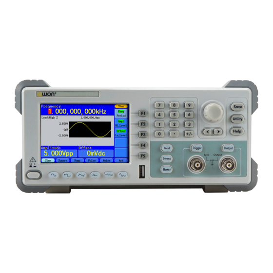
4.Quick Start Front/Rear Panel and User Interface Front Panel ① ② ③ ④ ⑤ ⑥ ⑫ ⑩ ⑨ ⑧ ⑬ ⑪ ⑦ Figure 4-1 Front panel overview Display the user interface ① LCD ② Menu selection Include 5 buttons: F1~F5 buttons ③... -
Page 11: Rear Panel
4.Quick Start ⑨ Trigger key In Sweep and N-Cycle Burst, if you choose Source as "Manual", every time you press this key, the generator will be triggered once. Activate or deactivate the output signal ⑩ Output key ⑪ Number keys Input parameters, include: number, point and plus/minus sign Include: Sine, Square, Ramp, Pulse, Noise and Arbitrary ⑫... -
Page 12: User Interface
4.Quick Start ⑨ LAN port Through this interface, the generator can be connected to your local network and controlled via PC software. Connect as a "host device" with an external USB device, ⑩ USB Host port such as connect a USB disk to the instrument. ⑪... -
Page 13: Foot Stool Adjustment
4.Quick Start make a check on the instrument according to the following steps: 1. Check whether there is any damage caused by transportation. If it is found that the packaging carton or the foamed plastic protection cushion has suffered serious damage, do not throw it away first till the complete device and its accessories succeed in the electrical and mechanical property tests. -
Page 14: Power On
4.Quick Start (3) Regulate the Power Switch to the desired voltage scale. Power On (1) Connect the instrument to the AC supply using the supplied power cord. Warning: To avoid electric shock, the instrument must be grounded properly. (2) Press down the power button at the front panel, the screen shows the boot screen. -
Page 15: Front Panel Operation
5.Front Panel Operation 5. Front Panel Operation This chapter will deal with the following topics mainly: How to Output Sine Signals How to Output Square Signals How to Output Ramp Signals How to Output Pulse Signals How to Output Noise Signals How to Output Arbitrary Signals How to Generate the Modulated Waveform How to Generate Sweep... -
Page 16: To Set Signals
5.Front Panel Operation To set signals The following describes how to set and output Sine, Square, Ramp, Pulse, Noise and Arbitrary signals. To Output Sine Signals Press button to call the user interface of Sine signal, the Sine waveform parameters can be set by operating the Sine setting menu on the right. The parameters of Sine waveform are: Frequency/Period, Amplitude/High Level, Offset/Low Level. -
Page 17: To Set The Amplitude
5.Front Panel Operation Figure 5-2: Set the frequency using number keys To Set the Amplitude Press F2 , confirm whether the "Ampl" menu item is highlighted; if not, press F2 to switch into "Ampl". In the Parameter bar 2, a cursor appears under the value of amplitude. Use the knob or the number keys to set the desired value. -
Page 18: To Set The Duty Cycle
5.Front Panel Operation Frequency Current parameter Current signal Parameter bar 1 Load Amplitude Setting menu of Offset Square signal Parameter bar 2 Duty cycle Figure 5-3: The User Interface of Square Signal Term Explanation Duty Cycle: The percentage that the High Level takes up the whole Period. To Set the Duty Cycle (1) Press F4 button, the "Duty"... -
Page 19: To Output Ramp Signals
5.Front Panel Operation To Output Ramp Signals Press button to call the user interface of Ramp signal, the Ramp waveform parameters can be set by operating the Ramp setting menu on the right. The parameters of Ramp waveform are: Frequency/Period, Amplitude/High Level, Offset/Low Level, Symmetry. -
Page 20: To Output Pulse Signals
5.Front Panel Operation Symmetry Current parameter Parameter bar 1 Input box Symmetry Figure 5-6: Set the symmetry of Ramp signal To Output Pulse Signals Press button to call the user interface of Pulse signal, the Pulse waveform parameters can be set by operating the Pulse setting menu on the right. The parameters of Pulse waveform are: Frequency/Period, Amplitude/High Level, Offset/Low Level, Pulse Width/Duty, Edge Time. -
Page 21: To Set The Pulse Width / Duty Cycle
5.Front Panel Operation Term Explanation Pulse Width: There are two kinds of Pulse Width—positive and negative. Positive Pulse Width is the time span between thresholds of 50% of the rising edge amplitude to the next 50% of the falling edge amplitude. Negative Pulse Width is the time span between thresholds of 50% of the falling edge amplitude to the next 50% of the rising edge amplitude. -
Page 22: To Output Noise Signals
5.Front Panel Operation (2) Turn the knob to change the value directly; or press the number keys to input the desired value and choose the unit. The Edge Time range is 8ns~1ms, and cannot exceed 40% of the Pulse Width. Edge time Current parameter Parameter bar 1... -
Page 23: To Output Arbitrary Signals
5.Front Panel Operation Figure 5-10: The User Interface of Noise Signal To Output Arbitrary Signals Press button to call the user interface of Arbitrary signal, the Arbitrary waveform parameters can be set by operating the Arbitrary setting menu on the right. The parameters of Arbitrary waveform are: Frequency/Period, Amplitude/High Level, Offset/Low Level, Built-in Waveform. -
Page 24: The User-Definable Waveform
5.Front Panel Operation Figure 5-12: The Exponential Fall Waveform Figure 5-13: The Sin(x)/x Waveform The User-Definable Waveform Press button and press F5 to select "Editable Wform". Menu item Instruction Create Wform Create a new waveform. Select Wform Select the waveform stored in Flash memory. Edit Wform Edit the stored waveform. -
Page 25: To Generate The Modulated Waveform
5.Front Panel Operation (3) Set the interpolation: Press F2 to switch between On/Off. If you choose On, the points will be connected with beelines; otherwise, the voltages between two consecutive points will not change, and the waveform looks like a step-up one. (4) Edit the waveform points: Press F3 to enter the operation menu. - Page 26 5.Front Panel Operation Waveform varies with the instantaneous voltage of the modulating waveform. The user interface of the AM is shown as below. Current Parameter AM Frequency Load Modulating Waveform Mod Depth Carrier Waveform Mod Type Mod Shape Source Carrier Waveform Carrier Carrier Frequency...
-
Page 27: Fm (Frequency Modulation)
5.Front Panel Operation FM (Frequency Modulation) The modulated waveform consists of two parts: the Carrier Waveform and the Modulating Waveform. The Carrier Waveform can only be Sine. In FM, the frequency of the Carrier Waveform varies with the instantaneous voltage of the modulating waveform. The user interface of the FM is shown as below. -
Page 28: Pm (Phase Modulation)
5.Front Panel Operation Note: The Sum of the Deviation and the Carrier Frequency should be equal to or less than maximum frequency of the selected function plus 1kHz. For an External Source, the Deviation is controlled by the voltage Level of the signal connected to the Modulation In connector in the rear panel. -
Page 29: Fsk (Frequency Shift Keying)
5.Front Panel Operation Waveform and the Carrier Waveform ranging from 0° to 180°. FSK (Frequency Shift Keying) The FSK Modulation is a modulation method, the output frequency of which switches between two the pre-set frequencies (Carrier Waveform Frequency and the Hop Frequency). -
Page 30: Pwm (Pulse Width Modulation)
5.Front Panel Operation Term Explanation FSK Rate: The frequency at which the output frequency shifts between the carrier frequency and the Hop frequency (Internal Modulation only). PWM (Pulse Width Modulation) The modulated waveform consists of two parts: the Carrier Waveform and the Modulating Waveform. -
Page 31: To Generate Sweep
5.Front Panel Operation menu item of the Pulse setting menu when you exit the Modulation mode). The maximum range of the Duty Deviation is the smaller one in [Pulse Duty, 1-Pulse Duty]. The maximum range of the Width Deviation is Pulse Width. To Generate Sweep In the frequency sweep mode, the generator "steps"... -
Page 32: To Generate Burst
5.Front Panel Operation (6) Press F4 to select StopFreq or FreqSpan, and set the desired value. (7) Press F5 to select NextPage, press it again to enter the next page. (8) Press F1 to select the source. Internal means using the internal source. External means using the Ext Trig/FSK/Burst connector in the rear panel to input the external signal. -
Page 33: Set The N-Cycle Burst
5.Front Panel Operation Set the N-Cycle Burst Burst Period Current Parameter Load Start Phase N Cycle Cycles Waveform Delay Source Waveform Figure 5-20: The User Interface of N-Cycle Burst (1) When the output signal is Sine, Square, Ramp, Pulse or Arbitrary waveform, press Burst function button to enter the Burst mode. -
Page 34: Set The Gated Burst
5.Front Panel Operation Set the Gated Burst Current Parameter Load Positive Start Phase Gated Waveform Source Waveform Figure 5-21: The User Interface of Gated Burst (1) When the output signal is Sine, Square, Ramp, Pulse or Arbitrary waveform, press Burst function button to enter the Burst mode. (2) Press button to choose the waveforms. -
Page 35: To Edit The File Name
5.Front Panel Operation (3) Remove the U disk: Remove the U disk from the USB Host port on the rear panel. The system will inform you "The USB device is removed", and the "USBDEVICE" in the storage menu will disappear. To Edit the File Name In file system, the user can edit the name of a file or a folder. -
Page 36: To Set The Screen Saver
5.Front Panel Operation (1) Press Utility and choose Disp Setup, press F2 to select Sep. (2) Press F2 to switch between Comma, Space, Off. Take the Frequency parameter for instance: Comma Space To Set the Screen Saver The screen saver will run automatically if no operation is taken for any key within the set time. -
Page 37: To Set The Sync Output
5.Front Panel Operation To Set the Sync Output The Generator provides Sync output through the Sync output terminal on the Front Panel. All standard output functions (except DC and Noise) have a corresponding Sync Signal. For some Sync applications, they can be disabled if users do not want to use them. Steps for setting the Sync Output: (1) Press Utility and choose Output Setup, press F2 to select Sync. -
Page 38: To Set The Dc Output
5.Front Panel Operation For the External Gated Burst, the Sync Signal follows the External Gated Signal. But, please note that this signal will not turn Level Low until the end of the last period (If the Waveform has a relative starting phase, it may be not zero intersections). To Set the DC Output (1) Press Utility and choose Output Setup, press F3 to select DC. -
Page 39: To Set The System
5.Front Panel Operation To Set the System Language Setting Press Utility and choose System, press F1 to switch between English/Chinese. Power On Setting (1) Press Utility and choose System, press F2 to select Power On. (2) Press F2 to switch between Default/Last. Default means that all the settings return to default when powered. -
Page 40: To Set The Beep
5.Front Panel Operation Burst Default Frequency 1kHz Count 1 Cycle Period 1 sec Phase 0° 延迟 I/O Configuration Default GPIB(IEEE-488) Baud Rate 115200 bps Parity No (8 bits) IP Address 192.168.1.99 Port 3000 Gate Way 192.168.1.1 Others Default Source Internal Signal Output Switch Sync Signal Output DC Voltage... -
Page 41: To Use Built-In Help
5.Front Panel Operation (1) Press Utility and choose System, press F4 to enter the second page of the menu. (2) Press F3 to select Clock. (3) Press F3 to switch between Internal/External. Use Built-in Help (1) Press Help function button, the catalog will display in the screen. (2) Press F1 or F2 to choose help topic, or just turn the knob to choose. -
Page 42: Communication With Pc
PC screen and guide you to install the USB driver. The driver is in the "USBDRV" folder under the directory where the ultrawave communication software is installed, such as "C:\Program Files\OWON\ultrawave\USBDRV". (3) Port setting of the software: Run the ultrawave software; click the "MENU" button in the top right corner. - Page 43 6.Communication with PC not support obtaining an IP address automatically, you should assign a static IP address. Here we set the IP address to 192.168.1.71. Figure 6-2: Set the network parameters of the computer (3) Set the network parameters of the ultrawave software. Run the software on the computer, choose the "Ports-settings"...
- Page 44 6.Communication with PC ultrawave software, the connection is successful. How to connect with the computer through a router: (1) Connection. Use a LAN cable to connect the Waveform Generator with a router, the LAN port of the Waveform Generator is in the rear panel; the computer should be connected to the router too.
-
Page 45: Using Com Port
6.Communication with PC Figure 6-5: Set the network parameters of the ultrawave software (4) Set the network parameters of the Waveform Generator. In the Waveform Generator, press Utility and choose I/O Setup, press F2 to choose LAN, enter the submenu. Set the IP Addr and the Port to the same value as the "Ports-settings" in the software in step (3). -
Page 46: Troubleshooting
7.Troubleshooting 7. Troubleshooting 1. The instrument is powered on but no Display. Check if the power is connected properly. Check if the Power Switch is in the proper voltage scale. Check if the fuse which is below the AC Power socket is used appropriately and in good condition (the cover can be pried open with a straight screwdriver). -
Page 47: Technical Specifications
8.Technical Specifications 8. Technical Specifications All these specifications apply to the AG4151 Waveform Generator unless otherwise explanation. To reach these specifications, the instrument must have been operating continuously for more than 30 minutes within the specified operating temperature. All the specifications are guaranteed unless those marked with “typical”. Waveforms Standard Waveforms Sine, Square, Ramp, Pulse, White Noise... - Page 48 8.Technical Specifications Phase Noise (when the Amplitude is 20 MHz:<10 kHz offset 1 Vp-p) -110 dBc/Hz (typical) Residue Clock Noise -57 dBm (typical) Square Rise/Fall Time <10ns (10%~90%) (typical, 1kHz, 1Vpp) Jitter (rms) 300ps + 100ppm of period (typical) Non-symmetry (below 50% Duty 1% of period+ 5ns Cycle) Overshoot...
- Page 49 8.Technical Specifications Internal Modulating Waveforms Sine, Square, Ramp, White Noise, Arbitrary Internal Modulating Frequency 2 mHz to 20.00 kHz Phase Deviation 0°~180° Carrier Waveforms Sine Source Internal/ External Internal Modulating Waveforms 50% duty cycle square Internal Modulating Frequency 2 mHz to 1.000 MHz Carrier Waveforms Pulse Source...
- Page 50 8.Technical Specifications External Reference Clock Output Impedance 50 kΩ, AC coupled Amplitude 5 Vp-p, access 50Ω Trigger Output Level TTL-compatible Output Impedance 50Ω (typical) Pulse Width >400ns (typical)
- Page 51 8.Technical Specifications Display Display Type 3.9 inch colored LCD (Liquid Crystal Display) Display Resolution 480 (Horizontal) × 320 (Vertical) Pixels Display Colors 65536 colors, 8 bits, TFT screen Power Supply 100-240 VACRMS, 50/60Hz, CATⅡ Consumption Less than 50W 110V 125 V, F4AL Fuse 220V 250 V, F2AL...
-
Page 52: Appendix
9.Appendix 9. Appendix Appendix A: Enclosure Standard Accessories: A power cord that fits the standard of the destination country A USB cable A CD (PC link application software) A User Manual A BNC/Q9 cable Appendix B: General Care and Cleaning General Care Do not store or leave the instrument where the liquid crystal display will be exposed to direct sunlight for long periods of time.
Need help?
Do you have a question about the AG4151 and is the answer not in the manual?
Questions and answers