
Related Manuals for Owon SDS5032E(V


Summary of Contents for Owon SDS5032E(V
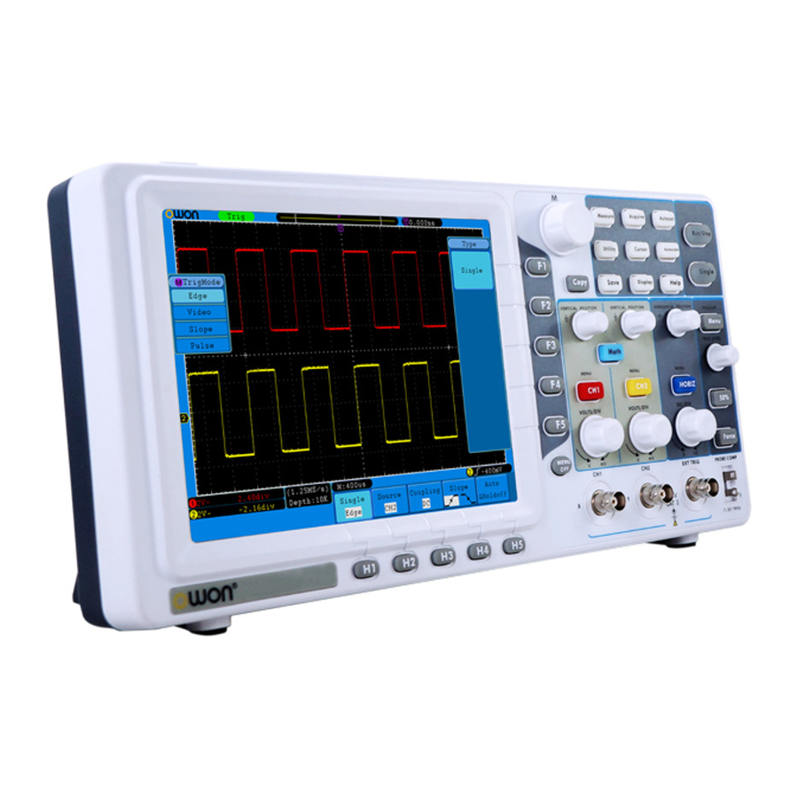
- Page 1 SDS5032E(V) Smart Digital Storage Oscilloscopes User Manual Note: "V" is for VGA port (optional) WWW.OWON.COM WWW.OWON.COM.HK WWW.OWON.COM.CN...
- Page 2 The information in this manual was correct at the time of printing. However, OWON will continue to improve products and reserves the rights to changes specification at any time without notice.
- Page 3 Please contact the nearest Lilliput's Sales and Service Offices for services or a complete copy of the warranty statement. For better after-sales service, please visit www.owon.com.hk and register the purchased product online. Excepting the after-sales services provided in this summary or the applicable warranty...
-
Page 4: Table Of Contents
Table of Contents 1. General Safety Requirements..................1 2. Safety Terms and Symbols....................2 3. General Characteristics....................4 4. Junior User Guidebook ....................5 Introduction to the Structure of the Oscilloscope..............6 Front Panel ............................... 6 Right Side Panel ............................7 Rear Panel .............................. - Page 5 How to Use Built-in Help........................70 How to Use Executive Buttons....................... 70 6. Demonstration ....................... 72 Example 1: Measurement a Simple Signal................72 Example 2: Gain of a Amplifier in a Metering Circuit ............73 Example 3: Capturing a Single Signal..................74 Example 4: Analyze the Details of a Signal................
-
Page 6: General Safety Requirements
1. General Safety Requirements 1. General Safety Requirements Before any operations, please read the following safety precautions to avoid any possible bodily injury and prevent this product or any other products connected from damage. In order to avoid any contingent danger, this product is only used within the range specified. -
Page 7: Safety Terms And Symbols
2. Safety Terms and Symbols 2. Safety Terms and Symbols Safety Terms Terms in this manual. The following terms may appear in this manual: Warning: Warning indicates the conditions or practices that could result in injury or loss of life. Caution: Caution indicates the conditions or practices that could result in damage to this product or other property. - Page 8 2. Safety Terms and Symbols Warning The channels should adopt common basis during measuring. To prevent short circuits, the 2 probe ground must not be connected to 2 different non-isolated DC level. The diagram of the oscilloscope ground wire connection: Probe Oscilloscope Electrical Outlet...
-
Page 9: General Characteristics
3. General Characteristics 3. General Characteristics Bandwidth: 30MHz; Sample rate(real time): Up to 250MS/s; Dual channel, 10K points on each channel for the Record length; Autoscale function; smart design body; 8 inch high definition TFT display (800 x 600 pixels); Built-in FFT function;... -
Page 10: Junior User Guidebook
4. Junior User Guidebook 4. Junior User Guidebook This chapter deals with the following topics mainly: Introduction to the structure of the oscilloscope Introduction to the user interface How to implement the general inspection How to implement the function inspection How to make a probe compensation How to set the probe attenuation coefficient How to use the probe safely... -
Page 11: Introduction To The Structure Of The Oscilloscope
4. Junior User Guidebook Introduction to the Structure of the Oscilloscope When you get a new-type oscilloscope, you should get acquainted with its front panel at first and the SDS5032E(V) digital storage oscilloscope is no exception. This chapter makes a simple description of the operation and function of the front panel of the SDS5032E(V) oscilloscope, enabling you to be familiar with the use of the SDS5032E(V) oscilloscope in the shortest time. -
Page 12: Right Side Panel
4. Junior User Guidebook Right Side Panel Fig. 4-2 Right side panel 1. USB Host port: It is used to transfer data when external USB equipment connects to the oscilloscope regarded as "host device". For example: use this port to save waveform file into USB flash disk. -
Page 13: Rear Panel
4. Junior User Guidebook Rear Panel Fig. 4-3 Rear Panel 1. Handle 2. Air vents 3. AC power input jack 4. Fuse 5. Foot stool (which can adjust the tilt angle of the oscilloscope) -
Page 14: Control (Key And Knob) Area
4. Junior User Guidebook Control (key and knob) Area Fig. 4-4 Keys Overview 1. Menu option setting: H1~H5 2. Menu option setting: F1~F5 3. Menu off:turn off the menu ○ 4. G knob (General knob): when a G symbol appears in the menu, it indicates you can turn the G knob to select the menu or set the value. -
Page 15: User Interface Introduction
4. Junior User Guidebook User Interface Introduction Fig. 4-5 Illustrative Drawing of Display Interfaces 1. Waveform Display Area. 2. The state of trigger, including: Auto: Automatic mode and acquire waveform without triggering. Trig: Trigger detected and acquire waveform. Ready: Pre-triggered data captured and ready for a trigger. Scan: Capture and display the waveform continuously. - Page 16 4. Junior User Guidebook 13. The frequency of the trigger signal of CH1. 14. It indicates the current function menu. 15. Current trigger type: Rising edge triggering Falling edge triggering Video line synchronous triggering Video field synchronous triggering The reading shows the trigger level value of the corresponding channel. 16.
-
Page 17: How To Implement The General Inspection
4. Junior User Guidebook How to Implement the General Inspection After you get a new SDS5032E(V) oscilloscope, it is recommended that you should make a check on the instrument according to the following steps: 1. Check whether there is any damage caused by transportation. If it is found that the packaging carton or the foamed plastic protection cushion has suffered serious damage, do not throw it away first till the complete device and its accessories succeed in the electrical and mechanical property tests. -
Page 18: How To Implement The Probe Compensation
4. Junior User Guidebook Connect the probe tip and the ground clamp to the connector of the probe compensator. 3. Press the "Autoset" Button. The square wave of 1 KHz frequency and 5V peak-peak value will be displayed in several seconds (see Fig. 4-6). Fig.4-6 Auto set Check CH2 by repeating Step 2 and Step 3. -
Page 19: How To Set The Probe Attenuation Coefficient
4. Junior User Guidebook Overcompensated Compensated correctly Under compensated Fig. 4-7 Displayed Waveforms of the Probe Compensation 3. Repeat the steps mentioned if needed. Fig. 4-8 Adjust Probe How to Set the Probe Attenuation Coefficient The probe has several attenuation coefficients, which will influence the vertical scale factor of the oscilloscope. -
Page 20: How To Use The Probe Safely
4. Junior User Guidebook Fig.4-9 Attenuation Switch Caution: When the attenuation switch is set to 1X, the probe will limit the bandwidth of the oscilloscope in 5MHz. To use the full bandwidth of the oscilloscope, the switch must be set to 10X. How to Use the Probe Safely The safety guard ring around the probe body protects your finger against any electric shock, shown as Fig. -
Page 21: Introduction To The Vertical System
4. Junior User Guidebook Cal"; run the program after everything is ready. Introduction to the Vertical System As shown in Fig.4-11, there are a few of buttons and knobs in VERTICAL CONTROLS. The following practices will gradually direct you to be familiar with the using of the vertical setting. -
Page 22: Introduction To The Horizontal System
4. Junior User Guidebook menu, symbols, waveforms and scale factor status information of the corresponding channel will be displayed in the screen. Introduction to the Horizontal System Shown as Fig.4-12, there are a button and two knobs in the "HORIZONTAL CONTROLS". - Page 23 4. Junior User Guidebook Fig.4-13 Trigger Control Zone 1. Press the "Trigger Menu" button and call out the trigger menu. With the operations of the menu selection buttons, the trigger setting can be changed. 2. Use the "TRIG LEVEL" knob to change the trigger level setting. By rotating the "TRIG LEVEL"...
-
Page 24: Advanced User Guidebook
5. Advanced User Guidebook 5. Advanced User Guidebook Up till now, you have already been familiar with the basic operations of the function areas, buttons and knobs in the front panel of the oscilloscope. Based the introduction of the previous Chapter, the user should have an initial knowledge of the determination of the change of the oscilloscope setting through observing the status bar. -
Page 25: How To Set The Vertical System
5. Advanced User Guidebook How to Set the Vertical System The VERTICAL CONTROLS includes three menu buttons such as CH1 MENU, CH2 MENU and Math, and four knobs such as VERTICAL POSITION, VOLTS/DIV for each channel. Setting of CH1 and CH2 Each channel has an independent vertical menu and each item is set respectively based on the channel. - Page 26 5. Advanced User Guidebook The description of the Channel Menu is shown as the following list: Function Menu Setting Description Pass both AC and DC components of the input signal. Coupling Block the DC component of the input signal. GROUND Disconnect the input signal.
- Page 27 5. Advanced User Guidebook probe is 1:1, the menu setting of the input channel should be set to X1. Take the Channel 1 as an example, the attenuation coefficient of the probe is 10:1, the operation steps is shown as follows: (1) Press the CH1 MENU button to show CH1 SETUP menu.
-
Page 28: Use Mathematical Manipulation Function
5. Advanced User Guidebook The waveform goes back to its original one as it is shown in Fig.5-4. Fig. 5-4 Original Waveform Fig. 5-5 Inverted Waveform Use Mathematical Manipulation Function The Mathematical Manipulation function is used to show the results of the addition, multiplication, division and subtraction operations between Channel 1 and Channel 2, and the FFT operation of Channel 1 or Channel 2. - Page 29 5. Advanced User Guidebook Fig. 5-6 Wave math menu The corresponding FCL (Functional Capabilities List) of the Waveform Calculation: Function Menu Setting Description Factor1 Select the signal source of the factor1 Dual Wfm Sign + - * / Select the sign of mathematical manipulation Math Factor 2...
-
Page 30: Using Fft Function
5. Advanced User Guidebook operation steps are as follows: 1. Press the Math button to bring up the Wfm Math menu. 2. Press the H1 button and call out the Dual Wfm Math menu. The menu will display at the left of the screen. 3. - Page 31 5. Advanced User Guidebook 5. Press F3 button to choose the Format, including dB, Vrms. 6. Press F4 button, the zoom window will display at the left of the screen, turn the G knob to zoom in or out the wave of the multiple including ×1, ×2, ×5, ×10. To select the FFT window ■...
- Page 32 5. Advanced User Guidebook Best solution for magnitude, worst for frequency. Recommend to use for: Blackman Single frequency waveforms, to find higher order harmonics. Fig.5-8, 5-9, 5-10, 5-11 are examples for measuring sine wave with a frequency of 1kHz under the selection of four different windows for FFT: Fig.5-8.
- Page 33 5. Advanced User Guidebook Fig.5-10 Hanning window Fig.5-11. Blackman window Notes for using FFT Use Zoom function to magnify the FFT waveform if necessary. Use the default dB scale for details of multiple frequencies, even if they have very different amplitudes. Use the Vrms scale to compare frequencies. DC component or offset can cause incorrect magnitude values of FFT waveform.
-
Page 34: Use Vertical Position And Volts/Div Knobs
5. Advanced User Guidebook What is Nyquist frequency? The Nyquist frequency is the highest frequency that any real-time digitizing oscilloscope can acquire without aliasing. This frequency is half of the sample rate. Frequencies above the Nyquist frequency will be under sampled, which causes aliasing. So pay more attention to the relation between the frequency being sampled and measured. -
Page 35: How To Set The Horizontal System
5. Advanced User Guidebook How to Set the Horizontal System The HORIZONTAL CONTROLS includes the HORIZ MENU button and such knobs as HORIZONTAL POSITION and SEC/DIV. 1. HORIZONTAL POSITION knob: this knob is used to adjust the horizontal positions of all channels (include those obtained from the mathematical manipulation), the analytic resolution of which changes with the time base. -
Page 36: Window Expansion
5. Advanced User Guidebook Fig. 5-14 Main Time Base Set Window Press the H2 menu selection button and choose Set. The screen will show a window area defined by two cursors. Use the HORIZONTAL POSITION and SEC/DIV knobs to adjust the horizontal position and size of this window area. In FFT mode, Set menu is invalid. - Page 37 5. Advanced User Guidebook Fig. 5-16 Zoom Window...
-
Page 38: How To Set The Trigger System
5. Advanced User Guidebook How to Set the Trigger System Trigger determines when DSO starts to acquire data and display waveform. Once trigger is set correctly, it can convert the unstable display to meaningful waveform. When DSO starts to acquire data, it will collect enough data to draw waveform on left of trigger point. -
Page 39: Video Trigger
5. Advanced User Guidebook Fig. 5-17 Edge trigger menu Edge menu list: Menu Settings Instruction Single Mode Edge Set vertical channel trigger type as edge trigger. Channel 1 as trigger signal. Channel 2 as trigger signal. Source External trigger as trigger signal EXT/5 1/5 of the external trigger signal as trigger signal. -
Page 40: Slope Trigger
5. Advanced User Guidebook Video menu list: MENU SETTING INSTRUCTION Single Mode Video Set vertical channel trigger type as video trigger Select CH1 as the trigger source Select CH2 as the trigger source Source The external trigger input EXT/5 1/5 of the external trigger source for increasing range of level NTSC Modu... -
Page 41: Pulse Width Trigger
5. Advanced User Guidebook Slew rate=( Slew rate High level- Low level)/ Settings Auto Acquire waveform even no trigger occurred Normal Acquire waveform when trigger occurred Mode Single When trigger occurs, acquire one waveform then stop Holdoff 100ns~10s, turn the G knob to set time interval Holdoff before another trigger occur. - Page 42 5. Advanced User Guidebook Term interpretation 1. Source: Trigger can occur from several sources: Input channels (CH1, CH2), Ext, Ext/5. Input: It is the most commonly used trigger source. The channel will work when selected as a trigger source whatever displayed or not. Ext Trig: The instrument can be triggered from a third source while acquiring data from CH1 and CH2.
-
Page 43: How To Operate The Function Menu
5. Advanced User Guidebook How to Operate the Function Menu The function menu control zone includes 8 function menu buttons: Measure, Acquire, Utility, Cursor, Autoscale, Save, Display, Help and 4 immediate-execution buttons: Autoset, Run/Stop, Single, Copy. How to Implement Sampling Setup Press the Acquire button and the menu is displayed in the screen, shown as Fig.5-25. - Page 44 5. Advanced User Guidebook Fig.5-26 Peak Detect mode, under which the burrs on the falling edge of the square wave, can be detected and the noise is heavy. Fig.5-27 Normal ACQU Mode display, in which no burr can be detected.
-
Page 45: How To Set The Display System
5. Advanced User Guidebook Fig.5-28 The displayed waveform after the noise is removed under the Average Mode, in which the average number of 16 is set. How to Set the Display System Press the Display button and the menu displayed in the screen is shown as Fig.5-29. Fig.5-29 Display Set Menu The description of the Display Set Menu is shown as follows: Function Menu... - Page 46 5. Advanced User Guidebook Display Type: With the F1 menu selection button pushed down, you can shift between Vect and Dots types. The differences between the two display types can be observed through the comparison between Fig.5-30 and Fig.5-31. Fig.5-30 Display in the Vector Form Fig.5-31 Display in Dots form Persist When the Persist function is used, the persistence display effect of the picture tube...
- Page 47 5. Advanced User Guidebook OFF, 1second, 2second, 5second and Infinity. When the "Infinity" option is set for Persist time, the measuring points will be stored till the controlling value is changed (see Fig.5-32). By pressing the F2 button, the persistence will be cleared. Fig.5-32 Infinite Persistence Display XY Format This format is only applicable to Channel 1 and Channel 2.
- Page 48 5. Advanced User Guidebook 1. Press the Display button and call out the Display Set Menu. 2. Press the H3 menu selection button to set XY Mode ON. The display format is changed to be XY mode (see Fig.5-33). Fig.5-33 XY Display Mode Cymometer It is a 6-digit cymometer.
-
Page 49: How To Save And Recall A Waveform
Save to internal storage or USB storage. If choose the USB storage, the file name is Internal Storage editable. The waveform file could be open External by OWON waveform analysis software (on the supplied CD). When the type is Setting, the menu shows as following:... - Page 50 5. Advanced User Guidebook Setting1 ….. Setting The setting address Setting8 Save the current oscilloscope setting to the Save internal storage Load Recall the setting from the selected address When the type is Image, the menu shows as following: Save the current display screen. The file can be only stored in a USB storage, so a USB Save storage must be connected first.
- Page 51 5. Advanced User Guidebook Fig.5-35 Wave Saving Tip: Whatever the Type of save menu is set, you can save the waveform by just pressing the Copy panel button in any user interface. If the Storage of the save menu is set as "External", you should install the USB disk.
-
Page 52: How To Record/Playback Waveforms
5. Advanced User Guidebook Delete the last character End and store Switch between Close the keyboard capital and small How to Record/Playback Waveforms Wave Record function can record the input current wave. You can set the interval between recorded frames in the range of 1ms~1000s.The max frame number reaches 1000,and you can get better analysis effect with playback and storage function. - Page 53 5. Advanced User Guidebook Fig.5-36 Wave Record Playback: Play back the wave recorded or saved. Playback menu shows as follows: Menu Setting Instruction Start frame Turn the G knob to select the number of start frame to playback (1~1000) End frame Turn the G knob to select the number of end frame Playback Mode to playback (1~1000)
- Page 54 5. Advanced User Guidebook Fig.5-37 Wave Playback Storage: Save the current wave according to the start frame and end frame set. Storage menu shows as follows: Menu Setting Instruction Turn the G knob to select the number of start frame Start frame Storage to store (1~1000)
-
Page 55: How To Implement The Auxiliary System Function Setting
5. Advanced User Guidebook To use wave record function, do as follows: (1) Press Save button. (2) Press H1 button, turn the G knob to choose Record. (3) Press H2 button. In the Mode menu, press F2 button to choose Record. (4) Press H3 button. - Page 56 5. Advanced User Guidebook Function Menu Setting Description Chinese Choose the display language of the operating Language English system. Others Display On/Off the date display Set Time Hour Min Setting Hour/Minute Month Setting Date/Month Year Setting Year Lock all keys. Unlock method: press 50% KeyLock button in trigger control area, then press Force button, repeat 3 times.
- Page 57 5. Advanced User Guidebook Do Self Cal (Self-Calibration) The self-calibration procedure can improve the accuracy of the oscilloscope under the ambient temperature to the greatest extent. If the change of the ambient temperature is up to or exceeds 5℃, the self-calibration procedure should be executed to obtain the highest level of accuracy.
- Page 58 5. Advanced User Guidebook The description of Pass/Fail Menu is shown as the follows: Function Menu Setting Description Enable Control enable switch operate Operate Control operate switch Pass Signal tested corresponds with the rule Fail Signal tested not correspond with the rule Output Beep Beep when it satisfies the rule...
- Page 59 5. Advanced User Guidebook Fig.5-44 Pass/Fail test Note: 1. When Pass/Fail is ON, if XY or FFT is ready to run, then Pass/Fail will be closed; under the mode of XY or FFT, Pass/Fail is unable. 2. Under the mode of Factory, Auto Scale and Auto Set, Pass/Fail will be closed. 3.
- Page 60 5. Advanced User Guidebook Using the LAN port, the oscilloscope can be connected with a computer directly, or through the router to connect. The network parameters can be set in the menu below. Press the Utility button and turn the G knob to select the LAN Set to go to the following menu.
- Page 61 5. Advanced User Guidebook Fig.5-47 Set the network parameters of the computer (3) Set the network parameters of the OWON Oscilloscope Software. Run the software on the computer, choose the "Ports-settings" of the "Communications" menu item. Set "Connect using" to LAN. About the IP, the first three bytes is same as the IP in the step (2), the last byte should be different.
- Page 62 5. Advanced User Guidebook (4) Set the network parameters of the oscilloscope. In the oscilloscope, press the Utility button and press H1 button, turn the G knob to select the LAN Set; press the H2 button, the set menu is displayed on the right. Set the IP and the Port to the same value as the "Ports-settings"...
- Page 63 5. Advanced User Guidebook Fig.5-50 Set the network parameters of the computer (3) Set the network parameters of the OWON Oscilloscope Software. Run the software on the computer; choose the "Ports-settings" of the "Communications" menu item. Set "Connect using" to LAN. About the IP, the first three bytes is same as the IP in the step (2), the last byte should be different.
-
Page 64: How To Measure Automatically
5. Advanced User Guidebook (4) Set the network parameters of the oscilloscope. In the oscilloscope, press the Utility button and press H1 button, turn the G knob to select the LAN Set; press the H2 button, the set menu is displayed on the right. Set the IP and the Port to the same value as the "Ports-settings"... - Page 65 5. Advanced User Guidebook Fig.5-53 Measure Menu The "Automatic Measurements" menu is described as the following table: Function Menu Setting Description Type Press F1 ,show the measure types Source Select the source Show all Show all the measures on the screen Add the selected measure types (shown at the left bottom, you could only add 8 types at most)
-
Page 66: The Automatic Measurement Of Voltage Parameters
5. Advanced User Guidebook G knob to choose Period. 5. Press the F4 button, the period options added completes. 6. Press the F1 button again, the type items will display at the left of screen, and turn the G knob to choose Freq. 7. - Page 67 5. Advanced User Guidebook Fig.5-55 Vpp: Peak-to-Peak Voltage. Vmax: The maximum amplitude. The most positive peak voltage measured over the entire waveform. Vmin: The minimum amplitude. The most negative peak voltage measured over the entire waveform. Vamp: Voltage between Vtop and Vbase of a waveform. Vtop: Voltage of the waveform's flat top, useful for square/pulse waveforms.
-
Page 68: How To Measure With Cursors
5. Advanced User Guidebook Fig.5-56 Rise Time: Time that the leading edge of the first pulse in the waveform takes to rise from 10% to 90% of its amplitude. Fall Time: Time that the falling edge of the first pulse in the waveform takes to fall from 90% to 10% of its amplitude. - Page 69 5. Advanced User Guidebook Function Setting Description Menu Switch off the cursor measurement. Type Voltage Display the voltage measurement cursor and menu. Time Display the time measurement cursor and menu. Display the channel generating the waveform to Source which the cursor measurement will be applied. When carrying out the cursor measurement, the position of Cursor 1 can be adjusted with the VERTICAL POSITION knob of Channel 1, and that of Cursor 2 can be adjusted with the VERTICAL POSITION knob of Channel 2.
- Page 70 5. Advanced User Guidebook channel CH1: 1. Press Cursor and recall the Cursor Measure menu. 2. Press the H2 button and choose CH1 for Source. 3. Press the H1 button, the Type menu will display at the right of the screen. Press the F3 button to select Time for Type, with two purple dotted lines displayed along the vertical direction of the screen, which indicating Cursor 1 and Cursor 2.
- Page 71 5. Advanced User Guidebook Fig.5-60 CURS MEAS Menu The description of the cursor measurement menu is shown as the following table: Function Setting Description Menu Switch off the cursor measurement. Type Vamp Display the Vamp measurement cursor and menu. Freq Display the Freq measurement cursor and menu.
- Page 72 5. Advanced User Guidebook Fig.5-61 wave of Vamp cursor measurement Carry out the following operation steps for the Freq cursor measurement: 1. Press Cursor and recall the Cursor Measure menu. 2. Press the H1 button, the Type menu will display at the right of the screen. Press the F3 button to select Freq for Type, with two purple dotted lines displayed along the vertical direction of the screen indicating the corresponding Cursor 1 and Cursor 2.
-
Page 73: How To Use Autoscale
5. Advanced User Guidebook Fig.5-62 wave of Freq cursor measurement How to Use Autoscale This is a very useful function for first time users to carry out a simple and quick test on the input signal. The function is applied to follow-up signals automatically even if the signals change at any time. - Page 74 5. Advanced User Guidebook Follow-up and adjust both vertical and horizontal settings. Follow-up and only adjust horizontal scale. Mode Follow-up and only adjust vertical scale. Show Multi-period waveforms. Wave Only show one or two periods. If you want to measure the two-channel signal, you can do as the follows: 1.
-
Page 75: How To Use Built-In Help
5. Advanced User Guidebook triggering. In this case, making Triggering or Coupling settings have no effect. 5. At the mode of Autoscale, if adjust the vertical position, voltage division, trigger level or time scale of CH1 or CH2, the oscilloscope will turn off Autoscale function. - Page 76 5. Advanced User Guidebook Run/Stop: Enable or disable sampling on input signals. Notice: When there is no sampling at STOP state, the vertical division and the horizontal time base of the waveform still can be adjusted within a certain range, in other words, the signal can be expanded in the horizontal or vertical direction.
-
Page 77: Demonstration
6. Demonstration 6. Demonstration Example 1: Measurement a Simple Signal The purpose of this example is to display an unknown signal in the circuit, and measure the frequency and peak-to-peak voltage of the signal. Carry out the following operation steps for the rapid display of this signal: (1) Set the probe menu attenuation coefficient as 10X and that of the switch in the probe switch as 10X (see "How to Set the Probe Attenuation Coefficient"... -
Page 78: Example 2: Gain Of A Amplifier In A Metering Circuit
6. Demonstration settings of channel 2. Then, the period, frequency, mean and peak-to-peak voltage will be displayed at the bottom left of the screen and change periodically (see Fig.6-1). Fig.6-1 Measure Frequency and PK-PK value for a given signal Example 2: Gain of a Amplifier in a Metering Circuit The purpose of this example is to work out the Gain of an Amplifier in a Metering Circuit. -
Page 79: Example 3: Capturing A Single Signal
6. Demonstration of the screen (See Fig.6-2). (9) Calculate the amplifier gain with the following formulas. Gain = Output Signal / Input signal Gain (db) = 20×log (gain) Fig.6-2 Waveform of Gain Measurement Example 3: Capturing a Single Signal It's quite easy to use Digital Oscilloscope to capture non-periodic signal, such as a pulse and burr etc. - Page 80 6. Demonstration (6) Press the Trigger Menu button to display the Trigger menu. (7) Press the H1 button to display the Trigger Type menu. (8) Turn the G knob to choose Edge as the mode. (9) Press the H2 button to display the Source menu. (10) Press the F1 button to choose CH1 as the source.
-
Page 81: Example 4: Analyze The Details Of A Signal
6. Demonstration Example 4: Analyze the Details of a Signal Noise is very common inside most of the electronic signal. To find out what's inside the noise and reduce the level of noise is very important function our oscilloscope is capable to offer. -
Page 82: Example 5: Application Of X-Y Function
6. Demonstration (2) Press the H1 button to display ACQU Mode menu. (3) Press the F3 button, turn the G knob and observe the waveform obtained from averaging the waveforms of different average number. User would see a much reduced random noise level and make it easy to see more details of the signal itself. - Page 83 6. Demonstration (4) Turn the VOLTS/DIV knob, making the amplitudes of two signals equal in the rough. (5) Press the Display button and recall the Display menu. (6) Press the H3 button and choose XY Mode as ON. The oscilloscope will display the input and terminal characteristics of the network in the Lissajous graph form.
-
Page 84: Example 6: Video Signal Trigger
6. Demonstration Example 6: Video Signal Trigger Observe the video circuit of a television, apply the video trigger and obtain the stable video output signal display. Video Field Trigger For the trigger in the video field, carry out operations according to the following steps: (1) Press the Trigger Menu button to display the trigger menu. -
Page 85: Troubleshooting
7. Troubleshooting 7. Troubleshooting 1. Oscilloscope is powered on but no Display. Check whether the power connection is connected properly. Check whether the fuse which is beside the is blew (the cover AC power input jack can be pried open with a straight screwdriver). Restart the instrument after completing the checks above. -
Page 86: Technical Specifications
8. Technical Specifications 8. Technical Specifications Unless otherwise specified, the technical specifications applied are for SDS5032E(V) only, and Probes attenuation set as 10X. Only if the oscilloscope fulfills the following two conditions at first, these specification standards can be reached. This instrument should run for at least 30 minutes continuously under the specified operating temperature. - Page 87 8. Technical Specifications Performance Characteristics Instruction Single: Interval( T △ ) ±(1 interval time+100ppm×reading+0.6ns); accuracy Average>16: (DC~100MHz) ±(1 interval time +100ppm×reading+0.4ns) A/D converter 8 bits resolution (2 Channels simultaneously) Sensitivity 5mV/div~5V/div Displacement ±10 div Analog bandwidth 30MHz Single bandwidth Full bandwidth Vertical system Low Frequency ≥5Hz (at input, AC coupling, -3dB)
- Page 88 8. Technical Specifications Trigger: Performance Characteristics Instruction Internal ±6 div from the screen center Trigger level range ±600mV EXT/5 ±3V Internal ±0.3div Trigger level ±(40mV + 6% of Set Value) Accuracy (typical) EXT/5 ±(200mV +6% of Set Value) Trigger According to Record length and time base displacement Trigger Holdoff 100ns~10s...
-
Page 89: General Technical Specifications
8. Technical Specifications General Technical Specifications Display Display Type 8" Colored LCD (Liquid Crystal Display) Display Resolution 800 (Horizontal) × 600 (Vertical) Pixels Display Colors 65536 colors, TFT screen Output of the Probe Compensator Output Voltage About 5V, with the Peak-to-Peak ≥1MΩ. -
Page 90: Appendix
9. Appendix 9. Appendix Appendix A: Enclosure Standard Accessories: A pair of Passive probe: 1.2 m, 1:1 (10:1) 1x CD (PC link application software) 1x Power cord: up to the standards of the country in which it is used. 1x USB cable 1x User Manual Appendix B: General Care and Cleaning General Care...
Need help?
Do you have a question about the SDS5032E(V and is the answer not in the manual?
Questions and answers
2016年2月アマゾンさんよりSDS5032Eのオシロスコープを購入しました。長い間放置していたのですが、久しぶりに使ってみようと思いクイックガイドを開いたのですが英語でさっぱりわからず、日本語マニュアルをダウンロードしようと思ったのですが、ダウンロード出来ず困っています。PC見ながら使っています。