
Related Manuals for ADLINK Technology Matrix MXC-4000 Series


Summary of Contents for ADLINK Technology Matrix MXC-4000 Series
- Page 1 Matrix MXC-4000 Series User’s Manual Manual Revision: 2.01 Revision Date: June 23, 2011 Part Number: 50-1Z068-1010 Advance Technologies; Automate the World.
- Page 2 Matrix MXC-4000 Series User’s Manual This page intentionally left blank.
-
Page 3: Table Of Contents
Matrix MXC-4000 Series User’s Manual Table of Contents Table of Contents..............iii List of Tables................v 1 Introduction ................ 1 Overview................1 Specifications............... 3 Unpacking Checklist ............5 2 System Description............7 Mechanical Drawings............7 2.1.1 Front View................ 7 2.1.2 Rear View ................ 8 2.1.3 Side View (Left) ............... - Page 4 Matrix MXC-4000 Series User’s Manual 2.4.6 Audio Jacks ..............24 2.4.7 Keyboard & Mouse PS2 Connectors ......24 2.4.8 Power Input Connector ..........25 Internal I/O Connectors............26 2.5.1 CompactFlash Socket............ 27 2.5.2 Fan Connector ............... 27 2.5.3 SATA Connector............27 2.5.4 Clear CMOS Button ............
-
Page 5: List Of Tables
Matrix MXC-4000 Series User’s Manual List of Tables Table 1-1: Specifications..............3 Table 2-1: MXC-4002D/4011D Connectors ........11 Table 2-2: LED Indicators ............... 12 Table 2-3: Digital I/O Connector ............. 14 Table 2-4: Active/Link LED ............. 19 Table 2-5: Speed LED ..............19 Table 2-6: VGA Connector.............. - Page 6 Matrix MXC-4000 Series User’s Manual This page intentionally left blank. List of Tables...
- Page 7 Matrix MXC-4000 Series User’s Manual Preface Copyright 2011 ADLINK TECHNOLOGY INC. This document contains proprietary information protected by copy- right. All rights are reserved. No part of this manual may be repro- duced by any mechanical, electronic, or other means in any form without prior written permission of the manufacturer.
-
Page 8: Getting Service
Address: 5215 Hellyer Avenue, #110, San Jose, CA 95138, USA Tel: +1-408-360-0200 Toll Free: +1-800-966-5200 (USA only) Fax: +1-408-360-0222 Email: info@adlinktech.com ADLINK Technology (China) Co., Ltd. Address: (201203) 300 Fang Chun Rd., Zhangjiang Hi-Tech Park, Pudong New Area, Shanghai, 201203 China Tel: +86-21-5132-8988 Fax:... - Page 9 Address: 84 Genting Lane #07-02A, Cityneon Design Centre, Singapore 349584 Tel: +65-6844-2261 Fax: +65-6844-2263 Email: singapore@adlinktech.com ADLINK Technology Singapore Pte. Ltd. (Indian Liaison Office) Address: No. 1357, "Anupama", Sri Aurobindo Marg, 9th Cross, JP Nagar Phase I, Bangalore - 560078, India Tel: +91-80-65605817 Fax: +91-80-22443548 Email:...
- Page 10 Matrix MXC-4000 Series User’s Manual This page intentionally left blank.
-
Page 11: Introduction
User’s Manual Introduction 1.1 Overview The Matrix MXC-4000 series is a fanless, embedded computer based on the next generation Intel® Atom™ D510 dual-core pro- cessor to offer greater computing power for your applications. The MXC-4000 inherits its exceptional fanless and cable-less design... - Page 12 PCI/PCIe cards installed. Combining a reliable design with more computing power and inno- vative features, the Matrix MXC-4000 series is the optimal choice to base your rugged application system on. Introduction...
-
Page 13: Specifications
Matrix MXC-4000 Series User’s Manual 1.2 Specifications Model Name MXC-4002D MXC-4011D System Core Processor Intel® Atom™ D510 1.66 GHz Dual-Core CPU Chipset Intel® I/O Controller Hub 8 Mobile (ICH8-M) VGA+LVDS display via DVI-D connector Video - Analog CRT, supports QXGA (2048 x 1536) resolution... - Page 14 Matrix MXC-4000 Series User’s Manual Weight 2.8 kg (6.16 lbs) Mounting Wall-mount kit Environmental Operating w/o FAN, w/o Card and w/o HDD: -10°C to 60°C Temperature Storage -40°C to 85°C Temperature Humidity ~95% @ 40°C (non-condensing) Operating, 5 Grms, 5-500 Hz, 3 Axes (w/CF or SSD) Vibration Operating, 0.5 Grms, 5-500 Hz, 3 Axes (w/HDD)
-
Page 15: Unpacking Checklist
Matrix MXC-4000 Series User’s Manual 1.3 Unpacking Checklist Before unpacking, check the shipping carton for any damage. If the shipping carton and/or contents are damaged, inform your dealer immediately. Retain the shipping carton and packing mate- rials for inspection. Obtain authorization from your dealer before returning any product to ADLINK. - Page 16 Matrix MXC-4000 Series User’s Manual This page intentionally left blank. Introduction...
-
Page 17: System Description
Matrix MXC-4000 Series User’s Manual System Description This section describes the appearance and connectors of the MXC-4000 controller, including chassis dimension, front panel connectors, and internal IO connectors. 2.1 Mechanical Drawings All dimensions shown are in mm. 2.1.1 Front View 117.8... -
Page 18: Rear View
Matrix MXC-4000 Series User’s Manual 2.1.2 Rear View System Description... -
Page 19: Side View (Left)
Matrix MXC-4000 Series User’s Manual 2.1.3 Side View (Left) 2.1.4 Side View (Right) 219.1 System Description... -
Page 20: Bottom View
Matrix MXC-4000 Series User’s Manual 2.1.5 Bottom View 15.9 183.1 2.1.6 Top View System Description... -
Page 21: Front Panel I/O Connectors
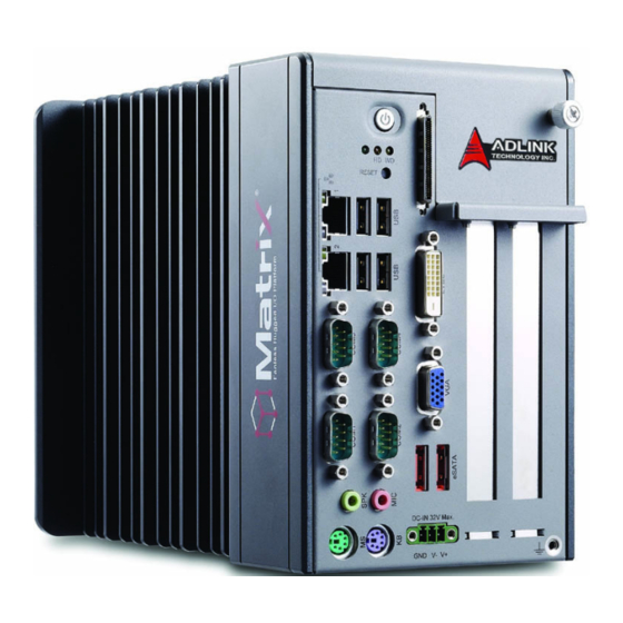
Matrix MXC-4000 Series User’s Manual 2.2 Front Panel I/O Connectors The MXC-4002D/4011D controller has the same I/O connector configuration on the front panel. This section describes functions of these I/O connectors. Symbol Function Symbol Function Power button COM ports LED indicators... -
Page 22: Power Button
Matrix MXC-4000 Series User’s Manual 2.2.1 Power Button The power button is a non-latched push button with a blue LED indicator. The system is turned on when button is pressed, and the power LED is also illuminated. To shut down the system, you can issue shutdown command via the operating system or just press the power button. -
Page 23: Digital I/O Connector
Matrix MXC-4000 Series User’s Manual 2.2.4 Digital I/O Connector The MXC-4002D/4011D controller features on-board isolated digi- tal I/O circuit and has a 68-pin VHDCI (Very High Density Cable Interconnect) connector on the front panel. The on-board digital I/ O card supports the following features:... -
Page 24: Table 2-3: Digital I/O Connector
Matrix MXC-4000 Series User’s Manual (1) VDD (24) IDI_1L (47) EOGND (2) EOGND (25) IDI_0H (48) IDO_10 (3) IDO_7 (26) IDI_0L (49) EOGND (4) EOGND (27) IDI_11 (50) IDO_9 (5) IDO_6 (28) IGND (51) EOGND (6) EOGND (29) IDI_10 (52) IDO_8... -
Page 25: Operating Principles
Matrix MXC-4000 Series User’s Manual 2.3 Operating Principles 2.3.1 Isolated Digital Input Isolated digital input utilizes an open collector transistor structure, with input voltage range of 0 V to 24 V and input resistance of 2.4K Ω. Connection between external signals and the MXC-4002D/ 4011D controller is as shown. -
Page 26: Isolated Digital Output
Matrix MXC-4000 Series User’s Manual 2.3.2 Isolated digital Output Common ground connection of isolated digital output and common power connection of isolated digital output are shown. When isolated digital output enters an “ON” state, sink current is conducted through the transistors. When an “OFF” state is entered, there is no current through the transistors. - Page 27 Matrix MXC-4000 Series User’s Manual Figure 2-3: Common Power Connection System Description...
-
Page 28: Gigabit Ethernet (Wg82574L)
Matrix MXC-4000 Series User’s Manual 2.4 Gigabit Ethernet (WG82574L) The MXC-4002D/4011D controller has two GbE ports on the front panel by Intel WG82574L Gigabit Ethernet controller. The Ethernet controller supports the following features: x1 PCI Express® interface with 2.5 GHz signaling... -
Page 29: Usb 2.0 Connectors
Matrix MXC-4000 Series User’s Manual Active/Link LED LED Color Status Description Ethernet port is disconnected Ethernet port is connected and no data transmission Yellow Ethernet port is connected and is transmitting/receiv- Flashing ing data. Table 2-4: Active/Link LED Speed LED... -
Page 30: Lvds Connector
Matrix MXC-4000 Series User’s Manual 2.4.2 LVDS Connector The MXC-4002D/4011D controller provides LCD panel function in the LVDS connector on the front panel. The MXC-4000 series supports only 18-bit one channel panel type. C_LVD_A_DATA2_ VCC_FPD C_LVD_A_DATA2_ DGND DGND C_LDDC_CLK C_LVD_EN... - Page 31 Matrix MXC-4000 Series User’s Manual 4.1.2.3 for the selection of setting RS-232/422/485 by BIOS of COM1 and COM2 ports. Signal Name RS-232 RS-422 RS-485 DCD# TXD422- 485DATA- RXD# TXD422+ 485DATA+ TXD# RXD422+ DTR# RXD422- DSR# RTS# CTS# System Description...
-
Page 32: Vga Connector
Matrix MXC-4000 Series User’s Manual 2.4.4 VGA Connector The D-sub 15-pin VGA connector is used to connect your MXC- 4002D/4011D controller to a monitor. The MXC-4000 series sup- ports only analog (VGA) monitors. PIN Signal Name GREEN BLUE DGND VGA_EN... -
Page 33: E-Sata Connectors
Matrix MXC-4000 Series User’s Manual 2.4.5 E-SATA Connectors The MXC-4002D/4011D controller has two E-SATA ports connec- tors on the front panel. The MXC-4000 series supports external storage expansion. PIN Signal Name DGND SATA1_TXP SATA1_TXN DGND SATA1_RXN SATA1_RXP DGND DGND SATA2_TXP... -
Page 34: Audio Jacks
Matrix MXC-4000 Series User’s Manual 2.4.6 Audio Jacks The MXC-4002D/4011D controller implements Intel High Definition audio using Realtek ALC262 chip. The HD audio supports up to 24-bit, 192 Kbps high quality headphone/speaker output and microphone input. Users can access the audio jacks on the front panel of MXC-4000 series. -
Page 35: Power Input Connector
Matrix MXC-4000 Series User’s Manual 2.4.8 Power Input Connector The DC power input connector of the MXC-4002D/4011D control- ler consists of three pins: V+, V- and chassis ground from right to left respectively. V+ and V- pins are for DC power input and chas- sis ground pin allows connect the chassis to ground for better EMC compatibility. -
Page 36: Internal I/O Connectors
Matrix MXC-4000 Series User’s Manual 2.5 Internal I/O Connectors The section describes the internal I/O connectors of the MXC- 4000 series. MXC-4002D and MXC- 4011D have the same inter- nal I/O connectors. The figure showed below is what’s inside the MXC-4000 series. -
Page 37: Compactflash Socket
Matrix MXC-4000 Series User’s Manual 2.5.1 CompactFlash Socket The internal CompactFlash socket is connected to chipset via IDE interface, and can be used as an alternative storage device for system installation. If want to boot up the MXC-4002D/4011D con- troller via a CF card with OS installed. Due to the nature of IDE interface, the CF card is not hot-pluggable and must be installed before system power on. -
Page 38: Clear Cmos Button
Matrix MXC-4000 Series User’s Manual 2.5.4 Clear CMOS Button When encountering the abnormal condition that causes the MXC- 4002D/4011D controller failed to boot, can try to clear the BIOS content stored in CMOS and restore to the default setting. To clear CMOS, just press the button and hold on for 1~2 second then release it. -
Page 39: Getting Started
Matrix MXC-4000 Series User’s Manual Getting Started This chapter demonstrates how to install the hard disk drive, PCI/ PCIe card and CompactFlash card into system. Additional COM ports jumper settings and and the MXC-4000 series wall-mount installation are also discussed. - Page 40 Matrix MXC-4000 Series User’s Manual 2. Hold the screw and pull it toward to your body side. Getting Started...
- Page 41 Matrix MXC-4000 Series User’s Manual 3. After removing the top cover, please use a screwdriver to unscrew two screws on the top side. Getting Started...
- Page 42 Matrix MXC-4000 Series User’s Manual 4. Place the chassis upside down and unscrew another two screws on the bottom side. 5. Pull the HDD bracket up. Getting Started...
- Page 43 Matrix MXC-4000 Series User’s Manual 6. Find the 4 M3 screws as accessories in the package. Fasten them to fix a 2.5” HDD or SSD to the bracket. Getting Started...
- Page 44 Matrix MXC-4000 Series User’s Manual 7. Gently push the HDD/SSD bracket down to the SATA connector on the PCB. 8. Reverse Step 3 and 4 to fasten the 4 screws. 9. Put the top cover back, and then fasten the thumbscrew.
-
Page 45: Installing Pci/Pcie Card
Matrix MXC-4000 Series User’s Manual 3.2 Installing PCI/PCIe card Please follow steps 1-2 in section 3.1 to remove the top cover before installing a PCI/PCIe card. 1. Insert your PCI or PCIe card to the PCI/PCIe slot. Note that there is a joint point on the lower side. Please make sure that the lower edge of your PCI/PCIe card is placed into the joint point. - Page 46 Matrix MXC-4000 Series User’s Manual 2. After installing your PCI/PCIe card, you can use the hold-on bars included with the MXC-4000 series to hold your card. Getting Started...
- Page 47 Matrix MXC-4000 Series User’s Manual 3. Adjust the position of hold-on bar to make it hold you card firmly. And tighten the screw to fix the hold-on bar. 4. Replace the top cover and fasten the thumbscrew. Getting Started...
-
Page 48: Installing A Cf Card
Matrix MXC-4000 Series User’s Manual 3.3 Installing a CF Card The MXC-4000 series controller provides an internal Compact- Flash socket to accommodate a CF card as a replacement of hard disk drive. Please follow steps 1-2 in section 3.1 to remove the top cover before installing a CF card. - Page 49 Matrix MXC-4000 Series User’s Manual 2. Gently push your CF card down to make it firmly attached to the internal CF socket. 3. Use the spacer supports fromaccessories in the pack- age, to prevent the CF card from coming loose.
-
Page 50: Plug-In Dc Power
Matrix MXC-4000 Series User’s Manual 3.4 Plug-in DC power Note: Before plugging DC power into the MXC-4000 seriescontroller, please make sure you have correct voltage and polarity for your DC input. An improper input voltage or polarity will cause system damage. -
Page 51: Mounting Mxc4000 Series Controller
Matrix MXC-4000 Series User’s Manual 3.5 Mounting MXC4000 Series Controller The MXC-4000 series controller is shipped with wall-mount brack- ets. You can use the wall-mount brackets and accessory screws to mount the MXC-4000 controller on the wall. The procedures of mounting MXC-4000 series are illustrated step by step below: 1. - Page 52 Matrix MXC-4000 Series User’s Manual 2. You can find two wall-mount brackets and four M4 screws in the accessory box shipped with the controller. Fasten four screws to fix the brackets to the chassis. 3. The final assembly is shown below. You can mount the MXC-4000 controller on the wall via proper screw holes, as shown in the mechanical drawings.
- Page 53 Matrix MXC-4000 Series User’s Manual 233.1 247.1 Figure 3-1: Wall-Mount Mechanical Drawing Figure 3-2: Fixed Wall-Mount Hole Getting Started...
- Page 54 Matrix MXC-4000 Series User’s Manual 10.0 Figure 3-3: Removable Wall-Mount Hole Getting Started...
-
Page 55: Bios Settings And Driver Installation
Matrix MXC-4000 Series User’s Manual BIOS Settings and Driver Installation 4.1 BIOS Setting The Basic Input/Output System (BIOS) is a program that provides a basic level of communication between the processor and periph- erals. In addition, the BIOS also contains codes for various advanced features applied to the MXC-4000 series controller. -
Page 56: Advanced
Matrix MXC-4000 Series User’s Manual 4.1.2 Advanced 4.1.2.1 CPU Configuration Hyper Threading Technology This option allows you to Enable/Disable Hyper-Threading Technology. Intel® SpeedStep Tech This option enables or disables Intel SpeedStep technology. 4.1.2.2 IDE Configuration ATA/IDE Configuration This option specifies whether the IDE channels should be ini- tialized in Compatible Mode or Enhanced Mode. - Page 57 Matrix MXC-4000 Series User’s Manual Third IDE Master Press < Enter > to configure the first device (master) on IDE interface. Third IDE Slave Press < Enter > to configure the second device (slave) on IDE interface. 4.1.2.3 SuperIO Configuration...
-
Page 58: Table 4-1: Suspend Mode
Matrix MXC-4000 Series User’s Manual 4.1.2.5 ACPI Configuration Suspend Mode This setting specifies either S1 (POS) or S3 (STR) system sus- pend mode. The Optimal and Fail-Safe Default setting is S3 (STR). Option Description Power On Suspend - Maintain current system status,... - Page 59 Matrix MXC-4000 Series User’s Manual 4.1.2.6 AHCI Configuration AHCI BIOS Support Enable or disable Advanced Host Controller Interface support. AHCI Port0 Press < Enter > to configure the AHCI Port0 device on AHCI interface. AHCI Port1 Press < Enter > to configure the AHCI Port1 device on AHCI interface.
-
Page 60: Table 4-2: Legacy Usb Support
Matrix MXC-4000 Series User’s Manual 4.1.2.7 USB Configuration Legacy USB Support Legacy USB Support also refers to USB mouse and keyboard support. Normally if this option is not enabled, attached USB mouse or keyboard will not be available until a USB compatible operating system fully boots up with USB drivers loaded. -
Page 61: Chipset
Matrix MXC-4000 Series User’s Manual 4.1.3 Chipset 4.1.3.1 North Bridge Configuration DRAM Frequency Specify DRAM frequency. You can specify whether let BIOS set DRAM frequency automatically or configure it manually (400 MHz or 533 MHz). Configure DRAM Timing by SPD Specify Enable to allow the timing setting of DRAM to be con- figured from SPD or Disable to configure it manually. -
Page 62: Table 4-3: Dvmt Mode Select
Matrix MXC-4000 Series User’s Manual DVMT Mode Select Dynamic Video Management Technology (DVMT) allows addi- tional system memory to be dynamically allocated in operating system for graphics usage. Once the application is closed, the allocated memory is released and is then available for system usage. -
Page 63: Table 4-4: Restore On Power Loss
Matrix MXC-4000 Series User’s Manual 4.1.3.2 South Bridge Configuration USB Function Specify the number of USB ports enabled in Matrix controller. The default value is 8 USB ports. USB 2.0 Controller This option depends on the setting of USB Function. If USB Function is set to Disabled, this option will have no effect. -
Page 64: Security
Matrix MXC-4000 Series User’s Manual 4.1.4 Security The Security setup menu provides both a Supervisor and a User password. If you use both passwords, the Supervisor password must be set first. To uninstall the passwords, you can simply set a NULL password. -
Page 65: Boot
Matrix MXC-4000 Series User’s Manual 4.1.5 Boot 4.1.5.1 Boot Settings Configuration Quick Boot Option Description Disabled Specify BIOS to perform all POST tests. Enabled Specify BIOS to skip certain POST test to boot faster. Quiet Boot Option Description Disabled Specify BIOS to display POST messages. - Page 66 Matrix MXC-4000 Series User’s Manual 4.1.5.2 Boot Device Priority Specify the priority of boot devices. All installed boot devices are detected during POST and displayed on the screen. You can refer to the following steps to specify different boot device.
-
Page 67: Exit
Matrix MXC-4000 Series User’s Manual 4.1.6 Exit Save Changes and Exit When you finish BIOS setting, please select this option to save all changes and reboot the system to make new setting takes effect. Discard Changes and Exit Select this option to discard all changes and exit BIOS setup.. -
Page 68: Driver Installation
Matrix MXC-4000 Series User’s Manual 4.2 Driver Installation After installing the operating system, you need to install all related drivers to make your system work accordingly. This section describes the drivers needed for Windows operating systems and the procedures to install them. For other OS support, please con- tact ADLINK for further information. -
Page 69: Install The Chipset Driver
Matrix MXC-4000 Series User’s Manual 4.2.1 Install the Chipset Driver This section describes the procedure to install the chipset driver of MXC-4000 series. The chipset driver outlines to the operating sys- tem how to configure the Intel® D150 chipset components in order... - Page 70 Matrix MXC-4000 Series User’s Manual Please follow the following steps to install the chipset driver for the MXC-4000 series: 1. Close any running application. 2. Insert the ADLINK All-in-One DVD. The chipset driver is located in the directory: x:\Driver Installation\Matrix\MXC-4000\Chipset\ where x: denotes the DVD-ROM drive.
-
Page 71: Install The Graphics Driver
Matrix MXC-4000 Series User’s Manual 4.2.2 Install the Graphics Driver This section describes the procedure to install the graphics driver of MXC-4000 series. The MXC-4000 series is equipped with Intel® 3150 graphics media accelerator integrated in Intel Mobile Intel® D510 chipset. The Intel® Graphics Media Accelerator... -
Page 72: Install The Ethernet Driver
Matrix MXC-4000 Series User’s Manual 4.2.3 Install the Ethernet Driver This section describes the procedure to install the Ethernet driver of MXC-4000 series. Please follow the steps to install the driver for Intel WG82574L Gigabit Ethernet controller. For Windows 2000 and XP users: 1. -
Page 73: Install The Audio Driver
Matrix MXC-4000 Series User’s Manual 4.2.4 Install the Audio Driver This section describes the procedure to install the audio driver of MXC-4000 series. The MXC-4000 series controller supports Intel High Definition audio using Realtek ALC262 audio codec. Please follow the steps to install audio driver for MXC-4000 series control- ler. -
Page 74: Install The Wdt Driver
Matrix MXC-4000 Series User’s Manual 4.2.5 Install the WDT Driver A WDT (watchdog timer) is a hardware mechanism to reset the system when the operating system or application is halted. A typi- cal usage of WDT is to start the timers and periodically reset the timer, and when timer is expired, the system resets. -
Page 75: A.1 Watchdog Timer (Wdt) Function Reference
Matrix MXC-4000 Series User’s Manual Appendix A.1 Watchdog Timer (WDT) Function Reference This appendix describes the usage of the watchdog timer (WDT) function library for the MXC-4000 controller. The watchdog timer is a hardware mechanism to reset the system in case the operating system or an application halts. - Page 76 Matrix MXC-4000 Series User’s Manual InitWDT @ Description Initialize the watchdog timer function of MXC-4000 series con- troller. InitWDT must be called before the invocation of any other WDT function. @ Supported controllers MXC-4000 series @ Syntax C/C++ BOOL InitWDT()
- Page 77 Matrix MXC-4000 Series User’s Manual SetWDT @ Description Set the timeout value of watchdog timer. There are two param- eters for this function to indicate the timeout ticks and unit. Users should call ResetWDT or StopWDT before the expiration of watchdog timer, or the system will be reset.
- Page 78 Matrix MXC-4000 Series User’s Manual StartWDT @ Description Start the watchdog timer function. Once the StartWDT is invoked, the countdown of watchdog timer starts. Users should call ResetWDT or StopWDT before the expiration of watchdog timer, or the system will be reset.
- Page 79 Matrix MXC-4000 Series User’s Manual ResetWDT @ Description Reset the watchdog timer. The invocation of ResetWDT allows users to restore the watchdog timer to the initial timeout value specified in SetWDT function. Users should call ResetWDT or StopWDT before the expiration of watchdog timer, or the sys- tem will be reset.
- Page 80 Matrix MXC-4000 Series User’s Manual StopWDT @ Description Stop the watchdog timer. @ Supported controllers MXC-4000 series @ Syntax C/C++ BOOL StopWDT() @ Parameters None @ Return codes TRUE if watchdog timer is successfully stopped. FALSE if watchdog timer is failed to stop.
Need help?
Do you have a question about the Matrix MXC-4000 Series and is the answer not in the manual?
Questions and answers