
Subscribe to Our Youtube Channel
Related Manuals for ADLINK Technology MXE-230 Series


Summary of Contents for ADLINK Technology MXE-230 Series
- Page 1 MXE-230 Series User’s Manual Ultra-compact Rugged Edge Computers with Intel ® N97 Processor Manual Rev.: 0.4 Preliminary Revision Date: September 11, 2024 Part Number: 50M-41055-1000...
- Page 2 Preface Copyright Copyright © 2024 ADLINK Technology, Inc. This document contains proprietary information protected by copyright. All rights are reserved. No part of this manual may be reproduced by any mechanical, electronic, or other means in any form without prior written permission of the manufacturer.
-
Page 3: Table Of Contents
MXE-230 Table of Contents Preface ..........................ii List of Tables ........................iv Introduction ........................ 1 Packing List ........................1 Optional Accessories ...................... 1 Features .......................... 1 Specifications ......................3 Core System ........................3 I/O Interface ........................3 Graphics .......................... 4 Audio .......................... -
Page 4: List Of Figures
List of Figures Figure 1: Functional Block Diagram ..................5 Figure 2: Onboard Connector Locations (Top) ............... 11 Figure 3: Mechanical Dimensions (Top) ................. 13 Figure 4: Mechanical Dimensions (Front) ................13 Figure 5: Mechanical Dimensions (Right Side) ..............14 Figure 6: Mechanical Dimensions (Left Side View) .............. -
Page 5: Introduction
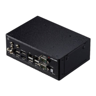
The MXE-230 Series include 1 HDMI, 1 DisplayPort, 4 USB ports, 2 gigabit LAN ports, 2 3-in-1 RS-232/422/485 serial ports, and a built-in TPM 2.0 module. Additional value and convenience are provided through a modular design with three independent slots for flexible system integration and expansion. - Page 6 This page intentionally left blank. Introduction...
-
Page 7: Specifications
MXE-230 2. Specifications Core System Intel® Alder Lake-N N97 series processor, 4-cores, 3.6GHz, 12W Memory Up to 16GB DDR5 4800MHz I/O Interface Expansion Slot M.2 Key-M supports NVMe SSDs at PCIe Gen3 x2 speed (2280 size). M.2 Key-B supports 3042 size cards with USIM slots for SIM cards, featuring USB3.0+USB2.0 interfaces (no PCIe support). -
Page 8: Graphics
2.3 Graphics 1x DP Interfaces 1x HDMI 2.4 Audio Audio Codec Realtek ALC888S 1x line-in, 1x line-out, MIC-in through 40pin box header Interfaces 2.5 Power Consumption Power off 3.9W In shutdown mode with DC input and only USB keyboard/mouse. System Idle 12.3W Under Windows Desktop with no application programs executed. -
Page 9: Functional Block Diagram
MXE-230 2.10 Functional Block Diagram Figure 1: Functional Block Diagram Specifications... - Page 10 This page intentionally left blank. Specifications...
-
Page 11: Quick Installation
MXE-230 3. Quick Installation This chapter covers the installation of M.2 expansion modules, wall mounting, and Din Rail, and also the integration of SATA SSDs for the ADLINK MXE-230. Installing M.2 Expansion Modules 1. Remove the top side screw*4. 2. Remove the screw*2 on the rear. 3. - Page 12 4. Remove the heat sink (Caution: Don’t break the thermal pad on the heat sink). 5. Install the M.2 module and reattach the heatsink, and seal it using the top cover Quick Installation...
-
Page 13: Wall Mounting
MXE-230 Wall Mounting Note: [1] While the configuration shown may indicate otherwise, due to the presence of antenna ports, for safety reasons, the device should ONLY be wall-mounted with the front and rear panels on the sides, NEVER on the top or underside. -
Page 14: Integrating Sata Ssd
Integrating SATA SSD Quick Installation... -
Page 15: Mechanical Layouts
MXE-230 4. Mechanical Layouts Figure 2: Onboard Connector Locations (Top) Table 1: Onboard Connector Locations Descriptions Onboard Connectors Item Description DDR5 slot SATA Port SATA Power Wafer M.2 M key connector M.2 E key connector M.2 B key connector Micro SIM slot AFM expansion board power AFM expansion board signal connector RTC Battery Header... - Page 16 This page intentionally left blank. Mechanical Layouts...
-
Page 17: Mechanical Dimensions
MXE-230 5. Mechanical Dimensions Top View Dimensions: mm Figure 3: Mechanical Dimensions (Top) Front View Dimensions: mm Figure 4: Mechanical Dimensions (Front) Mechanical Dimensions... - Page 18 Right Side View Dimensions: mm Figure 5: Mechanical Dimensions (Right Side) Left Side View Dimensions: mm Figure 6: Mechanical Dimensions (Left Side View) Mechanical Dimensions...
-
Page 19: Connectors And Jumpers
MXE-230 6. Connectors and Jumpers Front Panel IO Connectors 6.1.1 Power LEDs The power button is a non-latched push button with a blue LED indicator. System is turned on when button is pressed, and the power LED lit. If the system hangs, pressing the button for 5 seconds powers down the system. - Page 20 6.1.4 DisplayPort A single DisplayPort connector supporting DP 1.2 facilitates connectivity to VGA, DVI, HDMI, and DisplayPort monitors using adapter cables, supporting resolutions up to 4096 x 2160 at 60Hz. Signal Signal ML_Lane0_P ML_Lane3_N ML_Lane0_N Config1 ML_Lane1_P Config2 Aux_P ML_Lane1_N ML_Lane2_P Aux_N Hot Plug...
-
Page 21: Internal Io Connectors
MXE-230 6.1.7 DC Power Supply Connector 6.2 Internal IO Connectors 6.2.1 SATA Signal Signal SOC_SATA_TX1_P_C SOC_SATA_TX1_N_C SOC_SATA_RX1_N_C SOC_SATA_RX1_P_C +3.3V +3.3V +3.3V 6.2.2 M.2 M/E/B Keys M.2 Key-M support NVMe SSD, only supports PCIE GEN3 x2 speed. 2280 size card. M.2 Key-B connector support 3042 size card, and support USIM slots for SIM cards. Only support USB3.0+USB2.0 interface, no PCIE M.2 Key-E connector supports 2230 size card. - Page 22 6.2.3 Micro SIM Slot Using a SIM connector with a WWAN card that utilizes the M.2 B Key interface. 6.2.4 AFM Connector AFM connector is designed for additional ADLINK function board, while the function board connector is tailored for ODM project to design their own function boards to meet specific customer requirements. The AFM connector includes PCIE, USB2.0, SMBus, and LPC interface.
-
Page 23: Bios Setup
MXE-230 7. BIOS Setup Main Structure This section presents the primary menus of the AMIBIOS EFI BIOS setup utility. Use the following table as a quick ® reference for the contents of the BIOS Setup Utility. The subsections describe the submenus and options for each menu item. -
Page 24: Main Menu
Main Menu Upon entering the BIOS Setup Utility, the Main Menu is displayed, providing read-only information about your system and also allows you to set the System Date and Time. Refer to the tables below for details of the submenus and settings. - Page 25 MXE-230 7.3.2 Advanced > Power Management Feature Option Description Enables or disables the system’s ability to Hibernate Enable Hibernation Disabled, Enabled (OS/S4 Sleep State). This option may not be effective with some operating systems. Suspend Disabled, S3 Select the highest ACPI sleep state that the system ACPI Sleep State (Suspend to RAM) will enter when the SUSPEND button is pressed.
- Page 26 7.3.5 Advanced > Onboard Device Configuration Feature Option Description > Serial Port 1 Configuration COM1 Mode Control RS232, RS422, RS485 Select COM1 mode. RS232, RS422, RS485 > Serial Port 2 Configuration COM2 Mode Control RS232, RS422, RS485 Select COM2 mode. RS232, RS422, RS485 >...
- Page 27 MXE-230 7.3.7 Advanced > TPM 2.0 Configuration Feature Option Description Firmware Version: 600.18 Vendor: Enables or Disables BIOS support for security device. Security Device Support Disable, Enable O.S. will not show Security Device. TCG EFI protocol and INT1A interface will not be available. Active PCR banks Available PCR banks SHA256 PCR Bank...
-
Page 28: Chipset
Chipset 7.4.1 Chipset > Memory Configuration Feature Description Memory RC Version 0.0.4.74 Memory Frequency 4800 MHz tCL-tRCD-tRP-tRAS 40-39-39-77 MC 0 Ch 0 DIMM 0 Populated & Enabled Size 8192 MB (DDR5) Number of Ranks Manufacturer Transcend 7.4.2 Chipset > PCI Express Configuration Feature Option Description... -
Page 29: Security
MXE-230 7.4.5 Chipset > Security Configuration Feature Option Description Enable/Disable the PCH BIOS Lock Enable feature. BIOS Lock Disabled, Enabled Required to be enabled to ensure SMM protection of flash. Security Feature Option Description Administrator Password Set Administrator Password User Password Set User Password ►... - Page 30 Hard Disk, NVME, CD/DVD, SD, USB Hard Disk, USB CD/DVD, USB Key:UEFI: Boot Option #7 Sets the system boot order SanDisk, Partition 1, USB Floppy, USB Lan, Network, Disabled Hard Disk, NVME, CD/DVD, SD, USB Hard Disk, USB CD/DVD, USB Key:UEFI: Boot Option #8 Sets the system boot order SanDisk, Partition 1, USB Floppy, USB Lan,...
-
Page 31: Save & Exit
MXE-230 Save & Exit Feature Option Description Save Changes and Exit Exit the system setup after saving the changes. Discard Changes and Exit Exit the system setup without saving any changes. Reset the system after saving the changes. Save Changes and Reset Discard Changes and Reset Reset the system without saving any changes. -
Page 32: Safety Instructions
Safety Instructions Read and follow all instructions marked on the product and in the documentation before you operate your system. Retain all safety and operating instructions for future use. • Please read these safety instructions carefully. • Please keep this User‘s Manual for later reference. •... -
Page 33: Getting Service
5215 Hellyer Avenue, #110, San Jose, CA 95138, USA Tel: +1-408-360-0200 Toll Free: +1-800-966-5200 (USA only) Fax: +1-408-360-0222 Email: info@adlinktech.com ADLINK Technology (China) Co., Ltd. Address: 300 Fang Chun Rd., Zhangjiang Hi-Tech Park, Pudong New Area Shanghai, 201203 China Tel: +86-21-5132-8988 Fax: +86-21-5132-3588 Email: market@adlinktech.com...
Need help?
Do you have a question about the MXE-230 Series and is the answer not in the manual?
Questions and answers