
Related Manuals for ADLINK Technology MXE-5500 Series


Summary of Contents for ADLINK Technology MXE-5500 Series
- Page 1 MXE-5500 Series MXE-5501/MXE-5502/MXE-5503 Fanless Embedded Computer User’s Manual 2.00 Manual Rev.: Aug. 3, 2016 Revision Date: 50-1Z216-2000 Part No: Advance Technologies; Automate the World. SICK DIMA500...
- Page 2 Revision History Revision Release Date Description of Change(s) 2.00 Aug. 3, 2016 Initial Release 8024237/2019-03-25 • Subject to change without notice • SICK AG • Waldkirch • Germany • www.sick.com...
-
Page 3: Preface
MXE-5500 Preface Copyright 2016 ADLINK Technology, Inc. This document contains proprietary information protected by copy- right. All rights are reserved. No part of this manual may be repro- duced by any mechanical, electronic, or other means in any form without prior written permission of the manufacturer. - Page 4 Conventions Take note of the following conventions used throughout this manual to make sure that users perform certain tasks and instructions properly. Additional information, aids, and tips that help users perform tasks. NOTE: NOTE: Information to prevent minor physical injury, component dam- age, data loss, and/or program corruption when trying to com- plete a task.
-
Page 5: Table Of Contents
MXE-5500 Table of Contents Revision History..............ii Preface ..................iii List of Tables................ix List of Figures ................ xi 1 Introduction ................ 1 Features................2 Specifications............... 3 Unpacking Checklist ............5 Mechanical Drawings............6 Front Panel I/O Connectors ..........8 1.5.1 Power Button .............. - Page 6 1.7.1 Clearing CMOS Jumper..........21 1.7.2 DC 5V and 3.3V Connectors for GPS Module..21 1.7.3 USIM Port ..............22 1.7.4 Extendable Power/Reset/LED ........23 2 Getting Started ..............25 Unpacking Checklist ............25 Installing a Hard Disk Drive..........25 Installing a Mini-PCIe Device ..........
- Page 7 MXE-5500 B.2.11 TPM 1.2 Configuration..........60 B.2.12 Network Stack Configuration ........61 B.2.13 System Management..........62 Security................69 Boot ................... 70 B.4.1 Hard Drive BBS Priorities ......... 72 Save & Exit ................ 73 C Appendix: SEMA Utility ............ 75 System Overview Tab............75 C.1.1 Board Information .............
- Page 8 Important Safety Instructions..........91 Getting Service ..............95 viii Table of Contents 8024237/2019-03-25 • Subject to change without notice • SICK AG • Waldkirch • Germany • www.sick.com...
-
Page 9: List Of Tables
MXE-5500 List of Tables Table 1-1: LED Indicator Legend..........9 Table 1-2: DisplayPort Pin Assignment ........10 Table 1-3: Multi-Display Configuration........11 Table 1-4: DVI-I Connector Pin Assignment......12 Table 1-5: Gigabit Ethernet Port LED Function ......14 Table 1-6: COM Port Pin Assignments........ - Page 10 This page intentionally left blank. List of Tables 8024237/2019-03-25 • Subject to change without notice • SICK AG • Waldkirch • Germany • www.sick.com...
-
Page 11: List Of Figures
MXE-5500 List of Figures Figure 1-1: Functional Block Diagram..........5 Figure 1-2: Top View................6 Figure 1-3: Front View................ 7 Figure 1-4: Rear View ................ 7 Figure 1-5: (Left) Side View ............... 7 Figure 1-6: Front Panel I/O ..............8 Figure 1-7: Isolated/Differential Digital Input Circuit...... - Page 12 This page intentionally left blank. List of Figures 8024237/2019-03-25 • Subject to change without notice • SICK AG • Waldkirch • Germany • www.sick.com...
-
Page 13: Introduction
BT/WiFi and 3G. Leveraging proprietary mechanical engi- neering, the MXE-5500 series continues to offer all the popular features of the popular Matrix E series, including cable-free con- struction, wide operating temperature ranges, and 5 Grms vibra- tion resistance, having undergone, like all ADLINK Matrix devices, rigorous testing for operational verification. -
Page 14: Features
1.1 Features 6th Gen Intel® Core™ i7/i5/i3 Processors and QM170 chip- Single-side I/O with two SATA drive bays for easy drive swapping 1x DVI-I, 2x DisplayPort, 4x USB 2.0, 4x USB 3.0, and 4x GbE ports, 6x COM ports, 8x isolated DI/O, 2x SATA-III (6.0 Gb/s) port, ... -
Page 15: Specifications
MXE-5500 1.2 Specifications MXE-5501 MXE-5502 MXE-5503 System Core Intel® Core™ Intel® Core™ Intel® Core™ Processor i7-6820EQ i5-6440EQ i3-6100E Memory DDR4 2133 4GB (up to 32 GB) Graphics Display Port 2x DisplayPort DVI/VGA 1x DVI-I Ethernet 4x Intel GbE ports Serial Ports 6x COM (2x RS-232 + 4x RS-232/422/485) 4x USB 2.0 + 4x USB 3.0 Isolated 8 DI + 8 DO... - Page 16 MXE-5501 MXE-5502 MXE-5503 Weight 4 kg (8.81 lb) Mounting Wall-mount kit Environmental Standard: 0°C to 50°C Extended Temperature Options: -20°C to 60°C for Operating MXE-5501; Temperature* -20°C to 70°C for MXE-5502/5503 (w/Ind. SSD or CFast) Storage -40°C to 85°C (-40°F to 185°F) Temperature Humidity Approx.
-
Page 17: Unpacking Checklist
MXE-5500 DDR4 Intel DDPC DisplayPort 1 1333 to 2133MT/s Channel A SO-DIMM 0 Core Processor DisplayPort 2 DDPD Skylake –H DDR4 Channel B I3/i5/i7 1333 to 2133MT/s DDPB PTN3360D SO-DIMM 1 DVI-I Connector TDP:45W PTN3355D DMI GEN3(8GT/s) AFM Board AFM-IA-02 SATA III SATA port 1 PCIE x2... -
Page 18: Mechanical Drawings
1.4 Mechanical Drawings All dimensions shown are in millimeters (mm) unless otherwise stated. NOTE: NOTE: 235.47 204.00 230.00 Figure 1-2: Top View Introduction 8024237/2019-03-25 • Subject to change without notice • SICK AG • Waldkirch • Germany • www.sick.com... -
Page 19: Figure 1-3: Front View
MXE-5500 Figure 1-3: Front View Figure 1-4: Rear View 90.00 Figure 1-5: (Left) Side View Introduction 8024237/2019-03-25 • Subject to change without notice • SICK AG • Waldkirch • Germany • www.sick.com... -
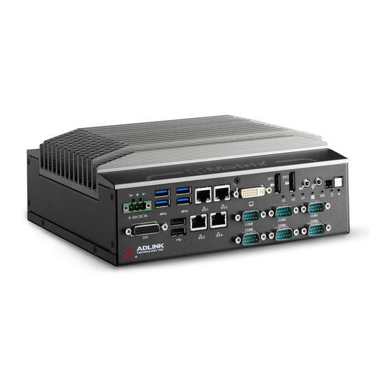
Page 20: Front Panel I/O Connectors
1.5 Front Panel I/O Connectors Figure 1-6: Front Panel I/O I/O connectors and controls on the MXE-5500 front panel, as labeled, are as follows Power Reset Power header LED indicators (x 6) Line-Out/Mic UART (x 6) ... -
Page 21: Power Button Header
MXE-5500 1.5.2 Power Button Header Allows connection of external power control cable. 1.5.3 Reset Button Executes hard reset for the MXE-5500. 1.5.4 LED Indicators In addition to the LED of the power button, LEDs on the front panel indicate the following operations. Color Description No physical storage is connected... -
Page 22: Displayport Connectors
1.5.5 DisplayPort Connectors Provide connection to VGA, DVI, HDMI monitor via DisplayPort 1.2 to VGA adapter cable, to DVI adapter cable, and to HDMI adapter cable. Signal Pin Signal CN_DDPx0+ CN_DDPx3- CN_DDPx0- CN_DDPx_AUX_SEL CN_DDPx1+ CN_DDPx_CONFIG2 CN_DDPx_AUX+ CN_DDPx1- CN_DDPx2+ CN_DDPx_AUX- CN_DDPx_HPD CN_DDPx2- CN_DDPx3+ +V3.3_DDPx_PWR... -
Page 23: Audio Connector
MXE-5500 Multi-Display Option With the computing and graphic performance enhancements of Intel HD Graphics Engine, the MXE-5500 supports three indepen- dent displays, configured as follows. DVI-D Max. Res Max. Res Max. Res Display 1 4096x2304 4096x2304 2048x1152 @60 Hz @60 Hz @60Hz Max. -
Page 24: Dvi-I Connector
1.5.7 DVI-I Connector For connection to external monitor, which can separate into indi- vidual VGA and DVI-D (single link) interfaces. Pin Signal Pin Signal Pin Signal DVI_Data2- DVI_Data2+ DVI clock+ DVI clock- Hot plug DVI DDC clock Analog Red detect DVI DDC data DVI_Data0- Analog Green... -
Page 25: Gigabit Ethernet Ports
MXE-5500 1.5.8 Gigabit Ethernet Ports The four Gigabit Ethernet ports are based on Intel WGI219/ WGI210/WGI211 GbE controllers. Port1 I219 Port2 I210 Port3 I211 Port4 I211 The ports feature: IEEE 802.3az Energy Efficient Ethernet IEEE 1588/802.1AS precision time synchronization ... -
Page 26: Com Port Connectors
Color Status Description Unlit 10Mbps Speed Green/Yellow Green 100 Mbps Yellow 1000 Mbps Table 1-5: Gigabit Ethernet Port LED Function 1.5.9 COM Port Connectors Of 6 COM ports through D-sub 9-pin connectors, COM1 to COM4 support RS-232/422/485 modes via BIOS setting, and COM5 and COM6 support only RS-232. -
Page 27: Usb 3.0 Ports
MXE-5500 Signal Table 1-6: COM Port Pin Assignments 1.5.10 USB 3.0 Ports USB 3.0 supporting Type A connection is compatible with Super- Speed, Hi-Speed, full-speed and low-speed USB devices, with support for multiple boot devices, including USB flash, USB exter- nal HDD, and USB CD-ROM drivers and boot priority and boot device configured in BIOS. -
Page 28: Db-26P Digital I/O Connector
1.5.13 DB-26P Digital I/O Connector 8CH isolated digital input and 8CH isolated digital output are pro- vided through the DB-26P connector. General purpose input/out- put application with isolation requirement is recommended. Signal Name Signal Name IDI_0L IDI_4H IDI_1L IDI_5H IDI_2L IDI_6H IDI_3L IDI_7H... -
Page 29: Table 1-9: Digital I/O Specifications
MXE-5500 8CH Isolated DI 8CH Isolated DO Output: Open Drain N- Channel Power Logic high: 5 to 24V MOSFET driver 250mA for all channels @ 60°C, 100% Logic low: 0 to 1.5V duty Input resistance: 2.4kΩ @ 0.5W Supply voltage: 5 to 35 VDC Interrupt source: DI Isolation voltage: 1.5kVDC channel 0 to 7 Isolation voltage: 1.5kV DC... -
Page 30: Figure 1-8: Isolated Digital Output Circuits
Isolated Digital Output Circuits Each isolation digital output channel adopts a MOSFET transistor, capable of driving peak current up to 250mA (sustained current up to 100 mA) with voltage ranges from 5V to 35V.The VDD pin is connected in serial with a flywheel diode to protect the driver dur- ing inductance loading, such as relay, motor, or solenoid. -
Page 31: Rear Panel
MXE-5500 1.6 Rear Panel Figure 1-10: Rear Panel I/O USB 2.0 (x 2) CFast C Antenna connection plugs (x 4) HDD/SDD Fast Plug (x 2) Table 1-10: Rear Panel I/O Connector Legend 1.6.1 CFast Slot The Type II push-push CFast host connector on the back panel connects to the host controller by SATA interface, supporting data transfer up to 6.0Gb/s (600MB/s)/3.0Gb/s (300MB/s)/1.5Gb/s (150MB/s). -
Page 32: Internal I/O Connectors
1.7 Internal I/O Connectors Mainboard is shown in default configuration, with stacked AFM board NOTE: NOTE: Figure 1-11: Internal I/O Power/Reset/LED GPS module power header (+3.3V) GPS module power header (+5V) Mini-PCIe slot 1 with USIM socket 1 Introduction 8024237/2019-03-25 • Subject to change without notice • SICK AG • Waldkirch • Germany • www.sick.com... -
Page 33: Clearing Cmos Jumper
MXE-5500 Mini-PCIe slot 2 with USIM socket 2 M.2 slot Clear CMOS jumper Table 1-11: Internal I/O Legend 1.7.1 Clearing CMOS Jumper Under conditions in which the MXE-5500 fails to boot, clearing the BIOS content stored in CMOS and restoring the default settings may be effective. -
Page 34: Usim Port
Description CN10 CN11 +3.3V Table 1-12: DC 5V and 3.3V Connectors Pin Assignments 1.7.3 USIM Port Use of 3.5G mini-PCIe module requires a SIM card for communi- cation with a telecom operator. The MXE-5500 provides two USIM modules connected to the mini-PCIe connector, with which SIM cards and 3.5G mini-PCIe modules can be installed to facilitate 3.5G communication. -
Page 35: Extendable Power/Reset/Led
MXE-5500 1.7.4 Extendable Power/Reset/LED The MXE-5500 provides internal LED connectors powering indica- tors for the Power/Reset button (from CN27), and Power for exter- nal controllable devices (CN25), assigned as shown. CN27 CN25 Figure 1-14: Extendable Reset/LED Configuration Description CN27 Power Button signal Reset Button signal CN25 +3.3VSB... - Page 36 This page intentionally left blank. Introduction 8024237/2019-03-25 • Subject to change without notice • SICK AG • Waldkirch • Germany • www.sick.com...
-
Page 37: Getting Started
MXE-5500 Getting Started This chapter discusses installation of hard disk drive, mini-PCIe module, and CFast card. In addition to connection and use of DIO and COM ports, wall-mount installation is also described. 2.1 Unpacking Checklist Before unpacking, check the shipping carton for any damage. If the shipping carton and/or contents are damaged, inform your dealer immediately. - Page 38 2. Withdraw the HDD rack. 3. Seat the HDD or SSD in the HDD rack. Getting Started 8024237/2019-03-25 • Subject to change without notice • SICK AG • Waldkirch • Germany • www.sick.com...
- Page 39 MXE-5500 4. Fix the HDD or SSD to the rack using the 4 included M3 screws. 5. Re-insert the rack and gently slide inward until the SATA connector is engaged. 6. Replace the 2 thumbscrews. 7. Repeat all steps for the left side HDD rack. Getting Started 8024237/2019-03-25 •...
-
Page 40: Installing A Mini-Pcie Device
2.3 Installing a Mini-PCIe Device 1. Remove the 6 fastening screws from the top cover. 2. Remove the 4 fastening screws from the top cover edges. 3. Remove the top cover Getting Started 8024237/2019-03-25 • Subject to change without notice • SICK AG • Waldkirch • Germany • www.sick.com... - Page 41 MXE-5500 4. Insert the mini-PCI-E wireless module into the module slot at an angle. 5. Seat the mini-PCI-E wireless module and use the 4 included M2.5-P-head-L5 screws to fix. Getting Started 8024237/2019-03-25 • Subject to change without notice • SICK AG • Waldkirch • Germany • www.sick.com...
- Page 42 6. Replace the top cover and the 10 fastening screws Getting Started 8024237/2019-03-25 • Subject to change without notice • SICK AG • Waldkirch • Germany • www.sick.com...
-
Page 43: Installing A Cfast Card
MXE-5500 2.4 Installing a CFast Card The MXE-5500 series controller provides an external CFast socket to accommodate a CFast card. 1. Remove the 2 fastening screws from the CFast cover. 2. Align the CFast card with the socket guide. 3. Gently insert the CFast card until it is firmly seated. -
Page 44: Connecting Dc Power
4. Replace the cover and the 2 fastening screws. 2.5 Connecting DC power Before introducing DC power to the MXE-5500, ensure the voltage and polarity provided are compatible with the DC input. Improper input voltage and/or polarity can be responsible for WARNING: system damage. -
Page 45: Wall-Mounting The Mxe-5500
MXE-5500 2.6 Wall-mounting the MXE-5500 All dimensions shown are in millimeters (mm) unless otherwise stated. NOTE: NOTE: To sustain structural integrity, the device should not be wall- mounted with the rear panel on the bottom. CAUTION: 1. Remove the 4 plastic pads and right and left side screws from the underside. -
Page 46: Cooling Considerations
3. Once final assembly is complete, mount the MXE-5500 series controller on the wall via the screw holes. 25.20 7.20 10.00 5.20 2.7 Cooling Considerations Heat-generating components of the MXE-5500 (such as CPU and PCH) are all situated on the top of the system. These components directly contact the heat sink via thermal pads and dissipate heat generated by the components. -
Page 47: Driver Installation
MXE-5500 sipation, maintain a minimum of 2 inches (5cm) clearance on the top of the MXE-5500. 2.8 Driver Installation Download requisite drivers, as follows, for your system from http:// www.adlinktech.com and install. Audio Chipset Graphic IRST ... - Page 48 This page intentionally left blank. Getting Started 8024237/2019-03-25 • Subject to change without notice • SICK AG • Waldkirch • Germany • www.sick.com...
-
Page 49: A Appendix: Watchdog Timer (Wdt)
Matrix WDT API library files and a demo program (incl. source code) can be downloaded from http://www.adlinktech.com/PD/ web/PD_detail.php?utm_source=&cKind=&pid=1631. To use the WDT function library for MXE-5500 series, include the header file matrix_wdt.h and linkage library matrix_wdt.lib in the C++ project. - Page 50 FALSE if watchdog timer fails to initialize. SetWDT Sets the timeout value of the watchdog timer. There are two parameters for this function to indicate the timeout ticks and unit. ResetWDT or StopWDT should be called before the expi- ration of watchdog timer, or the system will reset. @ Syntax C/C++ BOOL SetWDT(BYTE tick, BYTE unit)
- Page 51 MXE-5500 called before the expiration of watchdog timer, or the system will reset. @ Syntax C/C++ BOOL StartWDT() @ Parameters None @ Return codes TRUE if watchdog timer is successfully started. FALSE if watchdog timer is failed to start. ResetWDT Resets the watchdog timer.
-
Page 52: Di/O With Api/Windows
Matrix DI/O API library files and a demo program (incl. source code) are located on the included driver CD or downloaded from http://www.adlinktech.com. To use the DI/O function library for MXE-5500 series, include the header file matrix_dio.h and linkage library matrix_dio.lib in the C++ project. - Page 53 MXE-5500 GPI_Read() Reads the digital logic state of the digital input line.. @ Syntax C/C++ I16 GPI_Read(U16 *pwState) @ Parameters pwState Returns the digital logic state of MXE-5500 digital input chan- nels 1 to 8 (bit 0 to 7) @ Return code NoError ErrorOpenDriverFailed ErrorDeviceIoctl...
- Page 54 GPO_Read() Reads the digital logic state of the digital output line. @ Syntax C/C++ I16 GPO_Read(U16 *pwState) @ Parameters pwState Returns the digital logic state of MXE-5500 digital output chan- nels 1 to 8 (bit 0 to 7). @ Return code NoError ErrorOpenDriverFailed ErrorDeviceIoctl...
-
Page 55: B Appendix: Bios Setup
MXE-5500. The BIOS setup program includes menus for configuring settings and enabling features of the MXE-5500 series. Most users do not need to use the BIOS setup program, as the MXE-5500 ships with default settings that work well for most configurations. - Page 56 BIOS Information Shows current system BIOS Vendor, Core Version, BIOS Version, Board Version and Product Name. Platform Information Shows current system Platform Name, CPU Stepping, PCH SKU, PCH Stepping and GT information. FW Information Shows current system Memory RC version, Microcode Path, IGFX VBIOS version and ME FW version.
-
Page 57: Advanced
MXE-5500 System Time/System Date Allows adjustment of system time and date, as follows. 1. Highlight System Time or System Date using the up and down <Arrow> keys 2. Enter new values using the keyboard and select <Enter> 3. Select < Tab > to move between fields. The date must be entered in MM/DD/YY format, ... -
Page 58: Cpu Configuration
Accesses advanced options of the MXE-5500. B.2.1 CPU Configuration BIOS Setup 8024237/2019-03-25 • Subject to change without notice • SICK AG • Waldkirch • Germany • www.sick.com... - Page 59 MXE-5500 Hyper-Threading Enabled for Windows XP and Linux (optimized for Hyper-Thread- ing Technology) and Disabled for other OS (not optimized for Hyper-Threading Technology). When Disabled only one thread per enabled core is enabled. Active Processor Cores Number of cores to enable in each processor package. Intel Virtualization Technology When enabled, a VMM can utilize the additional hardware capabil- ities provided by Vanderpool Technology.
-
Page 60: Memory Configuration
Intel(R) SpeedStep(tm) Allows more than two frequency ranges to be supported. CPU C States Enable or disable CPU C states. Intel TXT(LT) Support Enables or Disables Intel(R) TXT(LT) support. TCC Activation Offset Offset from the factory TCC activation temperature. B.2.2 Memory Configuration Shows current system Memory RC Version and values for mem- ory frequency, total memory, DIMM#0, and DIMM#1. -
Page 61: System Agent (Sa) Configuration
MXE-5500 B.2.3 System Agent (SA) Configuration VT-d Enables/disables VT-d capability. BIOS Setup 8024237/2019-03-25 • Subject to change without notice • SICK AG • Waldkirch • Germany • www.sick.com... -
Page 62: Graphics Configuration
B.2.4 Graphics Configuration GTT Size Sets GTT size. Aperture Size Sets aperture size, with MMIO BIOS assignment exceeding 4GB automatically enabled when 2048MB aperture is selected, avail- able when CSM Support is disabled. DVMT Pre-Allocated Sets size of DVMT 5.0 pre-allocated (fixed) graphics memory used by the internal graphics device. -
Page 63: Onboard Devices Configuration
MXE-5500 B.2.5 Onboard Devices Configuration Serial Port 1 to 6 Configuration Sets port type (RS-232/422/485) for Serial Ports 1 to 4. LAN #1 (Intel I219LM) Enables/Disables onboard Intel I219LM LAN controller. LAN #1(I219LM) Launch PXE OpROM Enables or disables execution of LAN boot-rom to add boot option for legacy network devices. - Page 64 LAN #2(I210IT) Launch PXE OpROM Enables or disables execution of LAN boot-rom to add boot option for legacy network devices. LAN #3 (Intel I211AT) Enables/Disables onboard Intel I211AT LAN controller. LAN #3(I211AT) Launch PXE OpROM Enables or disables execution of LAN boot-rom to add boot option for legacy network devices.
- Page 65 MXE-5500 B.2.5.1 Serial Port Console Redirection Console Redirection Enables console redirection on COM 1, SOL, and EMS COM. Console Redirection Settings Sets miscellaneous parameters for COM Port 1, SOL, and EMS COM. BIOS Setup 8024237/2019-03-25 • Subject to change without notice • SICK AG • Waldkirch • Germany • www.sick.com...
-
Page 66: Advanced Power Management
B.2.6 Advanced Power Management State After G3 Determines the state the computer enters when power is restored after power loss, from among Last State, Power On, and Power Option Description Retains system power off after power is Power Off restored Power On Powers the system up when power is restored When power is restored, returns the system to... -
Page 67: Usb Configuration
MXE-5500 RTC Wake system from S5 Enable or disable system wake on alarm event, with FixedTime waking the system at the hr/min/sec specified, and DynamicTime waking the system at the current time + Increase minute(s). Wake On Ring Disables/Enable RI ping for Wake On Ring function. B.2.7 USB Configuration Legacy USB Support... - Page 68 XHCI Hand-off A workaround for OS without XHCI hand-off support, where XHCI ownership change should be claimed by the XHCI driver. USB Mass Storage Driver Support Enable/Disable USB mass storage driver support. Port 60/64 Emulation Enables I/O port 60h/64h emulation support, should be enabled for complete USB keyboard legacy support for OS not recognizing USB ports.
-
Page 69: Sata Configuration
MXE-5500 B.2.8 SATA Configuration SATA Mode Selection Sets SATA controller operation modes. M.2 Card Enables/disables M.2 card. SATA Port 1~2 Enables/disables SATA ports1 and 2. CFast Card Enables/disables CFast card. BIOS Setup 8024237/2019-03-25 • Subject to change without notice • SICK AG • Waldkirch • Germany • www.sick.com... -
Page 70: Csm Configuration
B.2.9 CSM Configuration CSM Support Enable or Disable CSM Support. GateA20 Active UPON REQUEST disables GA20 using BIOS services, and ALWAYS prevents GA20 from being disabled, useful when any RT code exceeding 1MB is executed. Option ROM Messages Sets display mode for Option ROM. Boot option filter Controls Legacy/UEFI ROM priority. -
Page 71: Amt Configuration
MXE-5500 Network Controls execution of UEFI and Legacy PXE OpROM. Storage Controls execution of UEFI and Legacy Storage OpROM. Video Controls execution of UEFI and Legacy Video OpROM. Other PCI devices Determines OpROM execution policy for devices other than Net- work, Storage, and Video. -
Page 72: Tpm 1.2 Configuration
Intel AMT Enables/disables Intel(R) Active Management Technology BIOS Extension. Note that iAMT H/W is always enabled. This option merely controls the BIOS extension execution. If enabled, addi- tional firmware is required in the SPI device. BIOS Hotkey Pressed OEMFLag Bit 1: Enables/disables BIOS hotkey press. B.2.11 TPM 1.2 Configuration Security Device Support Enables/disables BIOS support for security device, which the OS... -
Page 73: Network Stack Configuration
MXE-5500 TPM State Enables/disables Security Device. Reboot occurs during restart in order to change device state. Pending Operation Schedules operation for the security device. Reboot occurs during restart in order to change device state. B.2.12 Network Stack Configuration Network Stack Enables/disables UEFI Network Stack. -
Page 74: System Management
B.2.13 System Management BIOS Setup 8024237/2019-03-25 • Subject to change without notice • SICK AG • Waldkirch • Germany • www.sick.com... - Page 75 MXE-5500 B.2.13.1 Board Information BIOS Setup 8024237/2019-03-25 • Subject to change without notice • SICK AG • Waldkirch • Germany • www.sick.com...
- Page 76 B.2.13.2 Temperatures and Fan Speed BIOS Setup 8024237/2019-03-25 • Subject to change without notice • SICK AG • Waldkirch • Germany • www.sick.com...
- Page 77 MXE-5500 B.2.13.3 Power Consumption BIOS Setup 8024237/2019-03-25 • Subject to change without notice • SICK AG • Waldkirch • Germany • www.sick.com...
- Page 78 B.2.13.4 Runtime Statistics BIOS Setup 8024237/2019-03-25 • Subject to change without notice • SICK AG • Waldkirch • Germany • www.sick.com...
- Page 79 MXE-5500 B.2.13.5 Flags BIOS Setup 8024237/2019-03-25 • Subject to change without notice • SICK AG • Waldkirch • Germany • www.sick.com...
- Page 80 B.2.13.6 Power Up Power-Up Watchdog Resets the system a set amount of time after power up. BIOS Setup 8024237/2019-03-25 • Subject to change without notice • SICK AG • Waldkirch • Germany • www.sick.com...
-
Page 81: Security
MXE-5500 B.3 Security If only the Administrator password is set, access s limited and the password requested on Setup. If User password is set, it acts as a power-on password and must be entered to boot or enter setup. In Setup the user receives Administrator Password Sets Administrator Password. -
Page 82: Boot
BIOS Lock Enable/Disable the PCH BIOS Lock (BLE bit). B.4 Boot Setup Prompt Timeout Number of seconds before setup activation key is launched, with 65535(0xFFFF) setting indefinite waiting. Bootup Num-Lock State Sets keypad Number Lock status following boot. BIOS Setup 8024237/2019-03-25 •... - Page 83 MXE-5500 Quiet Boot Option Description Disabled Directs BIOS to display POST messages Enabled Directs BIOS to display the OEM logo. Fast Boot Option Description Disabled Directs BIOS to perform all POST tests. Directs BIOS to skip certain POST tests to boot Enabled faster.
-
Page 84: Hard Drive Bbs Priorities
B.4.1 Hard Drive BBS Priorities Specifies the priority of boot devices. All installed boot devices are detected during POST and displayed. Target Boot Option # and click to select the desired device. BIOS Setup 8024237/2019-03-25 • Subject to change without notice • SICK AG • Waldkirch • Germany • www.sick.com... -
Page 85: Save & Exit
MXE-5500 B.5 Save & Exit Discard Changes and Exit Discards all changes and exits BIOS setup Save Changes and Reset Saves all changes and reboots the system, with new settings tak- ing effect Discard Changes Resets system setup without saving any changes Restore Defaults Sets all BIOS options to default settings, designed for maximum system stability but less than maximum performance. - Page 86 Restore Defaults if the computer encounters system configuration problems. Save as User Defaults Saves all changes to this point as user defaults Restore User Defaults Restores user defaults to all setup options Launch EFI Shell from filesystem device Attempts to launch EFI Shell application (Shell.efi) from one of the available filesystem devices BIOS Setup 8024237/2019-03-25 •...
-
Page 87: C Appendix: Sema Utility
MXE-5500 Appendix C SEMA Utility The SEMA graphical interface is available for Windows operating systems. To get started in Windows, simply run SEMAGui.exe C.1 System Overview Tab C.1.1 Board Information This section shows general information about the board, BIOS Version and SEMA features supported. The first three lines show the firmware versions of the board. -
Page 88: System Health Tab
tain an ID-string and the respective build date. The next lines show the board ID, hardware revision, serial number, manufacturing/ repair date and MAC ID of the board. The last line shows all sup- ported SEMA features for this board. C.2 System Health Tab C.2.1 Temperatures &... -
Page 89: Power Consumption
MXE-5500 speeds of system fans 1 to 3 are also displayed in RPM. Note that not all platforms supply all information as shown, in which case N/ A is displayed in lieu of the value. C.2.2 Power Consumption Displays information for the main power supply in mA for current and W for power consumption, and are updated every second. -
Page 90: User Flash Memory Tab
C.3 User Flash Memory Tab The Read/Write Raw Data Storage in SEMA Flash Memory function is reserved for advanced SEMA applications. NOTE: NOTE: The Read/Write Raw Data Storage in SEMA Flash Memory func- tion is reserved for advanced SEMA applications. SEMA Utility 8024237/2019-03-25 •... -
Page 91: Memory
MXE-5500 C.3.1 Memory For Flash Memory organization, with address and size entered as hexadecimal values. Valid start addresses are multiples of 16 within the range: 0x0000-0x01F0 for 512 byte variants and 0x0000-0x03F0 for 1024 byte variants. Size can be any multiple of 16 bytes (up to the total memory size). - Page 92 Padding If the data length is not a multiple of four, the required number of pad (or fill) characters is appended. In String mode, a valid pad character can be any printable ASCII character or a pre- defined pad characters: - SPACE character (ASCII character 0x20) - NULL character (ASCII character 0x00) In Hex mode, any eight bit hex value (00..FF) is valid.
-
Page 93: Hardware Control Tab
MXE-5500 C.4 Hardware Control Tab C.4.1 Watchdog The watchdog timeout value is given in seconds and can be set at 1 to 65535 seconds, with a value of 0 seconds disabling the watchdog. When enabled, the watchdog should be triggered repeatedly within the timeout period to avoid system reset. -
Page 94: Backlight Control
When using the watchdog feature, all partitions must be mounted as read-only, to avoid file sys- tem corruption and data loss. NOTE: NOTE: It is not advisable to use the watchdog feature in a Windows environment, since Windows restart uses a safe shutdown procedure. - Page 95 MXE-5500 Temperature Fan PWM level Falls below 15°C Turns off Between 15°C and 60°C Between 40°C and 70°C Between 48°C and 80°C Exceeds 55°C 100% If the temperature drops below one of the trigger points, the lower PWM value is taken. NOTE: NOTE: SEMA Utility...
-
Page 96: Hardware Monitor Tab
C.5 Hardware Monitor Tab Shows Power Consumption and Temperatures information from the System Health Tab in a graphical format. When logging is enabled, all values queried every second, such as temperatures and power consumption, are recorded to a log file. At startup, logging is disabled by default. -
Page 97: I2C Bus Tab
MXE-5500 Logging ceases when Enable Logging is unchecked or the pro- gram closed, and suspended during a File Open dialog. Data is Recorded as simple ASCII text in tab-separated columns for easy import/export into any spreadsheet calculation program or other data processing tool. The first line written to the log file con- tains captions indicating the content and the respective unit of the data to be recorded. - Page 98 implemented. Both common bus speeds of 100 and 400kHz are supported. To read data from or write data to the BMC an address (8-bit) must be given as well as the amount of data to be transferred (length) plus the register offset. Data should then be handed over in hex values forming a hex string, as shown.
-
Page 99: Gpio Tab
MXE-5500 Start + Address/Write + Register /Command + Write Length + Data[1] + Data[2] + ... +Data[Length] + Stop Read/Write Block Start + Address/Write + Register /Command + Read Start + Address/Read + Length + Data[1] +Data[2] + ... + Data[Length] + Stop Write Start + Address/Write + Data[1] + Stop Read/Write Byte Read Start + Address/Read + Data[1] + Stop... -
Page 100: Gpio Information
C.7.1 GPIO information Controls GPIO direction, with each bit in the shown byte repre- senting a GPIO. To set a GPIO for output the bit must set to 0, and for input 1. Get Direction reads the current configuration and Set Direction sets the configuration to the value entered in the Input New Direction field. -
Page 101: Io Read
MXE-5500 C.7.2 IO Read Shows the current input values for all GPIOs, with those config- ured as output showing current output value. C.7.3 IO Write Sets outputs, with GPIOs configured as input not affected. C.7.4 IO XorAndXor Reads the GPIO input and applies the logic operation in order of the input fields, with the result set as output value. - Page 102 This page intentionally left blank. SEMA Utility 8024237/2019-03-25 • Subject to change without notice • SICK AG • Waldkirch • Germany • www.sick.com...
- Page 103 MXE-5500 Important Safety Instructions For user safety, please read and follow all instructions, Warnings, Cautions, and Notes marked in this manual and on the associated device before handling/operating the device, to avoid injury or damage. S'il vous plaît prêter attention stricte à tous les avertissements et mises en garde figurant sur l'appareil , pour éviter des blessures ou des dommages.
- Page 104 Never attempt to repair the device, which should only be serviced by qualified technical personnel using suitable tools A Lithium-type battery may be provided for uninterrupted backup or emergency power. Risk of explosion if battery is replaced with one of an incorrect type;...
- Page 105 MXE-5500 BURN HAZARD Touching this surface could result in bodily injury. To reduce risk, allow the surface to cool before touching. RISQUE DE BRÛLURES Ne touchez pas cette surface, cela pourrait entraîner des blessures. Pour éviter tout danger, laissez la surface refroidir avant de la toucher.
- Page 106 This page intentionally left blank. Important Safety Instructions 8024237/2019-03-25 • Subject to change without notice • SICK AG • Waldkirch • Germany • www.sick.com...
- Page 107 San Jose, CA 95138, USA Tel: +1-408-360-0200 Toll Free: +1-800-966-5200 (USA only) Fax: +1-408-360-0222 Email: info@adlinktech.com ADLINK Technology (China) Co., Ltd. Address: (201203) 300 Fang Chun Rd., Zhangjiang Hi-Tech Park Pudong New Area, Shanghai, 201203 China Tel: +86-21-5132-8988 Fax: +86-21-5132-3588 Email: market@adlinktech.com...
- Page 108 84 Genting Lane #07-02A, Cityneon Design Centre Singapore 349584 Tel: +65-6844-2261 Fax: +65-6844-2263 Email: singapore@adlinktech.com ADLINK Technology Singapore Pte. Ltd. (Indian Liaison Office) Address: #50-56, First Floor, Spearhead Towers Margosa Main Road (between 16th/17th Cross) Malleswaram, Bangalore - 560 055, India Tel: +91-80-65605817, +91-80-42246107 Fax:...
Need help?
Do you have a question about the MXE-5500 Series and is the answer not in the manual?
Questions and answers