
Related Manuals for ADLINK Technology MXE-1401


Summary of Contents for ADLINK Technology MXE-1401
- Page 1 MXE-1400 Series MXE-1401 Fanless Embedded Computer User’s Manual 2.50 Manual Rev.: Sept. 5, 2016 Revision Date: 50-1Z192-2010 Part No: Advance Technologies; Automate the World.
-
Page 2: Revision History
Revision History Revision Release Date Description of Change(s) 2.00 July 29, 2016 Initial Release Section 2.2 Adaptors & Additional 2.50 Sept. 5, 2016 Accessories added... -
Page 3: Preface
MXE-1400 Series Preface Copyright 2016 ADLINK Technology, Inc. This document contains proprietary information protected by copy- right. All rights are reserved. No part of this manual may be repro- duced by any mechanical, electronic, or other means in any form without prior written permission of the manufacturer. - Page 4 Conventions Take note of the following conventions used throughout this manual to make sure that users perform certain tasks and instructions properly. Additional information, aids, and tips that help users perform tasks. NOTE: NOTE: Information to prevent minor physical injury, component dam- age, data loss, and/or program corruption when trying to com- plete a task.
-
Page 5: Table Of Contents
MXE-1400 Series Table of Contents Revision History..............ii Preface ..................iii List of Tables................ix List of Figures ................ xi 1 Introduction ................ 1 Overview................1 Features................2 Specifications............... 3 Unpacking Checklist ............5 Mechanical Drawings............5 Front Panel I/O Connectors ..........8 1.6.1 Power Button .............. - Page 6 Optional Accessories for DB-26P Digital I/O Connector 18 Isolated Digital Input Circuits ........18 Isolated Digital Output Circuits ........18 Rear Panel ................. 20 1.7.1 CFast Slot ..............20 1.7.2 HDD Fast Plug Slot........... 20 Internal I/O Connectors............21 1.8.1 Clearing CMOS Jumper..........
- Page 7 MXE-1400 Series GPO_Read() ..............41 B Appendix: BIOS Setup ............43 Main ................... 44 B.1.1 BIOS Information ............44 B.1.2 System Time/System Date ........44 Advanced................45 CPU Configuration ............46 Memory Configuration ..........48 Onboard Device Configuration ........49 Advanced Power Management ........
- Page 8 C.2.4 Flags ................. 69 User Flash Memory Tab ............ 70 C.3.1 Memory..............71 C.3.2 Write Memory ............71 Hardware Control Tab............73 C.4.1 Watchdog ..............73 C.4.2 Backlight Control............74 C.4.3 Smart Fan ..............74 Hardware Monitor Tab ............76 I2C Bus Tab ...............
-
Page 9: List Of Tables
MXE-1400 Series List of Tables Table 1-1: Front Panel I/O Legend ..........8 Table 1-2: LED Indicator Legend..........9 Table 1-3: DisplayPort Pin Assignment ........10 Table 1-4: Multi-Display Configuration........11 Table 1-5: DVI-I Connector Pin Assignment......12 Table 1-6: Gigabit Ethernet Port LED Function ...... - Page 10 This page intentionally left blank. List of Tables...
-
Page 11: List Of Figures
MXE-1400 Series List of Figures Figure 1-1: MXE-1400 Functional Block Diagram......5 Figure 1-2: Top View..............6 Figure 1-3: Front View ..............7 Figure 1-4: Rear View ..............7 Figure 1-5: (Left) Side View ............7 Figure 1-6: Front Panel I/O ............8 Figure 1-7: Gigabit Ethernet Ports .......... - Page 12 This page intentionally left blank. List of Figures...
-
Page 13: Introduction
MXE-1400 Series Introduction 1.1 Overview ADLINK’s new Matrix MXE-1400 series of rugged quad-core fan- less computers, featuring the latest generation of Intel® Atom™ E3845 (codename: BayTrail) delivers outstanding processor per- formance with minimum power consumption. The MXE-1400 series accommodates rich I/O variety in a compact system, with DisplayPort, DVI-I (supporting both DVI and VGA sig- nals), 3 GbE by Intel network interface controllers, 6 USB 2.0, 1 USB 3.0 with dedicated bandwidth, 8 isolated DIO, and 6 COM... -
Page 14: Features
AFM (Adaptive Function Modules), whereby selection or custom- ization of I/O interfaces based on application requirements. Combing superior processor performance, wireless capability, and rich I/O with flexible expandability, all in a compact and robust package, the ADLINK MXE-1400 is an ideal choice for a wide range of applications including intelligent transportation, in-vehicle multimedia, surveillance, and factory automation. -
Page 15: Specifications
MXE-1400 Series 1.3 Specifications MXE-1401 System Core Processor Intel® Atom™ E3845 Chipset SoC design 2 independent displays out of 3 channels Video 1x VGA+ DVI by DVI-I connector 1x Display ports supports up to 2560 x 1600 2 GB DDR3L 1066 MHz SODIMM module (Up to... - Page 16 MXE-1401 Mounting Wall-mount kit Environmental Standard: 0°C to 50°C (w/HDD) Operating Temperature Extended Temperature: -40°C to 70°C (w/industrial SSD or CFAST) Storage Temperature -40°C to 85°C (excl. HDD/SDD/CFAST) Humidity Approx. 95% @ 40°C (non-condensing) Operating, 5 Grms, 5-500 Hz, 3 axes (w/ CFAST...
-
Page 17: Unpacking Checklist
Retain the shipping carton and packing materials for inspection. Obtain authorization from your dealer before returning any product to ADLINK. Ensure that the fol- lowing items are included in the package. MXE-1401 controller Wall-mount bracket (in Accessory Box) ... -
Page 18: Figure 1-2: Top View
All dimensions shown are in millimeters (mm) unless otherwise stated. NOTE: NOTE: Figure 1-2: Top View Introduction... -
Page 19: Figure 1-3: Front View
MXE-1400 Series Figure 1-3: Front View Figure 1-4: Rear View Figure 1-5: (Left) Side View Introduction... -
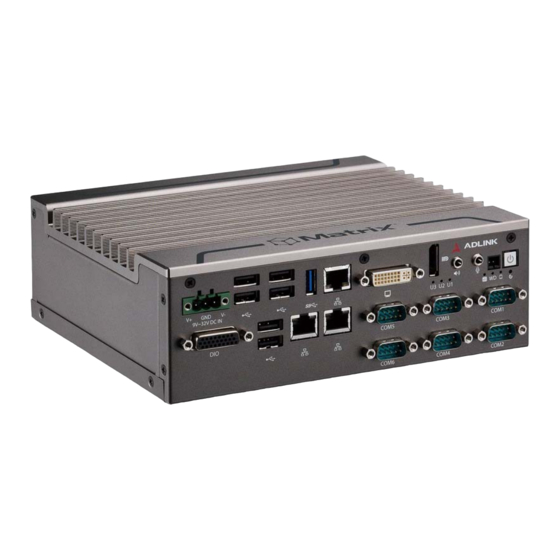
Page 20: Front Panel I/O Connectors
1.6 Front Panel I/O Connectors Figure 1-6: Front Panel I/O A Power B Reset C Power header D LED indicators Audio UART G DisplayPort H DVI-I I211Gigabit Ethernet USB 3.0 (1600mA supported) K USB 2.0 DC power supply M DB-26P digital I/O Table 1-1: Front Panel I/O Legend Introduction... -
Page 21: Power Button
MXE-1400 Series 1.6.1 Power Button Non-latched push button with a blue LED indicator. System is turned on when button is pressed, and the power LED lit. If the system hangs, depressing the button for 5 seconds powers down the system. 1.6.2 Power Button Header Allows connection of external power control cable. -
Page 22: Displayport Connector
1.6.5 DisplayPort Connector Provides connection to VGA, DVI, HDMI monitor via DisplayPort 1.2 to VGA adapter cable, to DVI adapter cable, and to HDMI adapter cable. Signal Pin Signal CN_DDPx0+ CN_DDPx3- CN_DDPx0- CN_DDPx_AUX_SEL CN_DDPx1+ CN_DDPx_CONFIG2 CN_DDPx_AUX+ CN_DDPx1- CN_DDPx2+ CN_DDPx_AUX- CN_DDPx_HPD CN_DDPx2- CN_DDPx3+ +V3.3_DDPx_PWR... -
Page 23: Multi-Display Option
MXE-1400 Series Multi-Display Option With the computing and graphic performance enhancements of Intel HD Graphics Engine, the MXE-1400 supports two indepen- dent displays, configured as follows. VGA by DP Display 1 Display 2 2560 x 1600 2560 x 1600 2048 x 1280 Max. -
Page 24: Dvi-I Connector
1.6.7 DVI-I Connector For connection to external monitor, which can separate into indi- vidual VGA and DVI-D (single link) interfaces. Pin Signal Pin Signal Pin Signal DVI_Data2- DVI_Data2+ DVI clock+ CRT DDC clock 14 DVI clock- CRT DDC data Hot plug DVI DDC clock Analog Red detect... -
Page 25: Gigabit Ethernet Ports
MXE-1400 Series 1.6.8 Gigabit Ethernet Ports 3 Gigabit Ethernet ports are based on the Intel i211-AT GbE con- troller, featuring: IEEE 802.3az Energy Efficient Ethernet IEEE 1588/802.1AS precision time synchronization IEEE 802.3Qav traffic shaper Interrupt moderation, VLAN support, IP checksum offload ... -
Page 26: Com Port Connectors
Color Status Description Unlit Ethernet port is disconnected. Ethernet port is connected with no Active/Link Yellow activity. Ethernet port is connected and Flashing active. Unlit 10Mbps Green/ Speed Green 100 Mbps Orange Orange 1000 Mbps Table 1-6: Gigabit Ethernet Port LED Function 1.6.9 COM Port Connectors Of 6 COM ports through D-sub 9-pin connectors, COM1 to COM4... -
Page 27: Usb 3.0 Ports
MXE-1400 Series Signal TXD422+ 485DATA+ RXD422+ DTR# RXD422- DSR# RTS# CTS# Table 1-7: COM Port Pin Assignments 1.6.10 USB 3.0 Ports USB 3.0 supporting Type A connection is compatible with Super- Speed, Hi-Speed, full-speed and low-speed USB devices, with support for multiple boot devices, including USB flash, USB external HDD, and USB CD-ROM drivers and boot priority and boot device configured in BIOS. -
Page 28: Dc Power Connector
1.6.13 DC Power Connector The DC power supply connector consists of V+, chassis ground, and V- pins (from right to left), with V+ and V- pins accepting DC power input and chassis ground pin enhancing EMC compatibility. The DC power input accepts input from 9V DC to 32 VDC. Signal V+(DC_IN) GND(CHGND) -
Page 29: Table 1-9: Db-26P Connector Pin Assignment
MXE-1400 Series Signal Name Signal Name IDI_3L IDI_7H IDI_45L EOGND EOGND IDO_0 IDI_67L IDO_1 +VDD IDO_2 +5DIO_CN_ISO IDO_3 IDI_0H IDO_4 IDI_1H IDO_5 IDI_2H IDO_6 IDI_3H IDO_7 Table 1-9: DB-26P Connector Pin Assignment 8CH Isolated DI 8CH Isolated DO Output: Open Drain N- Channel Power Logic high: 5 to 24V MOSFET driver 250mA for all channels @ 60°C, 100%... -
Page 30: Optional Accessories For Db-26P Digital I/O Connector
Optional Accessories for DB-26P Digital I/O Connector Accessory DIN-37D-01 Terminal board with one 37-pin D- 91-14025-1020 sub connector and DIN-rail mounting DIO-to-DIN37 cable (26-pin to 37-pin) 30-01143-0000 Isolated Digital Input Circuits The input can accept voltages up to 24V, with 2.4kΩ input resis- tors. -
Page 31: Figure 1-11: Isolated Digital Output Circuits
MXE-1400 Series Figure 1-11: Isolated Digital Output Circuits Figure 1-12: Isolated Digital Output Sample Application Circuit Introduction... -
Page 32: Rear Panel
1.7 Rear Panel Figure 1-13: Rear Panel I/O A Antenna connection plugs (X4) CFast Slot HDD Fast Plug Slot Table 1-11: MXE-1400 Rear Panel I/O Connector Legend 1.7.1 CFast Slot The Type II push-push CFast host connector on the back panel connects to the host controller by SATA interface, supporting data transfer up to 3.0Gb/s (300MB/s)/1.5Gb/s (150MB/s). -
Page 33: Internal I/O Connectors
MXE-1400 Series 1.8 Internal I/O Connectors Mainboard is shown in default configuration, with stacked AFM board NOTE: NOTE: Figure 1-14: Internal I/O Extended Reset/LED wafer GPS module power header – 5V GPS module power header – 3.3V USB 2.0 connector Clear CMOS jumper USIM slot Mini-PCIE slot... -
Page 34: Clearing Cmos Jumper
1.8.1 Clearing CMOS Jumper Under conditions in which the MXE-1400 fails to boot, clearing the BIOS content stored in CMOS and restoring the default settings may be effective. To clear CMOS, short Pin #1 and Pin #2 of JP1 and remove the jumper, after which the CMOS will be restored to factory default settings. -
Page 35: Usim Port
MXE-1400 Series CN9 CN10 Figure 1-16: DC 5V and 3.3V Connectors Configuration Description CN10 +3.3V Table 1-14: DC 5V and 3.3V Connectors Pin Assignments 1.8.3 USIM Port Use of 3.5G mini-PCIe module requires a SIM card for communi- cation with a telecom operator. The MXE-1400 provides a USIM port connected to the mini-PCIe connector, with which a SIM card and 3.5G mini-PCIe module can be installed to facilitate 3.5G communication. -
Page 36: Extended Power/Reset/Led
state disk (SSD), requiring installation into the SATA connector with a HDD bracket. 1.8.5 Extended Power/Reset/LED Internal LED connectors power indicators for the Power (from CN27) and Reset buttons (CN31), assigned as shown. CN9 CN10 Figure 1-17: Extended Reset/LED Configuration Description CN27 +V3.3SB... -
Page 37: Getting Started
MXE-1400 Series Getting Started This chapter discusses installation of hard disk drive, mini-PCIe module, and CFast card. In addition to connection and use of DIO and COM ports, wall-mount installation is also described. 2.1 Unpacking Checklist Before unpacking, check the shipping carton for any damage. If the shipping carton and/or contents are damaged, inform your dealer immediately. - Page 38 1. Remove thumbscrews fixing the HDD hatch. 2. Withdraw the HDD bracket. Getting Started...
- Page 39 MXE-1400 Series 3. Place the HDD or SSD into the bracket. 4. Use the 4 provided M3 screws to fix the unit to the bracket. 5. Gently slide the bracket back into the bay until the SATA connector on the PCB is engaged. 6.
-
Page 40: Installing A Mini-Pcie Device
2.4 Installing a Mini-PCIe Device Remove the bottom cover before installing. 1. Remove 6 bottom screws. 2. Remove 4 side screws (2 from each side). Getting Started... - Page 41 MXE-1400 Series 3. Lift the bottom cover 4. Insert the mini-PCI-E wireless module into the slot at an angle. 5. Gently seat the mini-PCI-E wireless module and fix with the 4 M2.5-P-head-L5 screws. Getting Started...
-
Page 42: Installing Cfast Card
6. Replace the cover and refasten the 10 screws. 2.5 Installing CFast Card The MXE-1400 provides an external CFast socket to accommo- date one CFast card for additional storage. 1. Remove the 2 screws and the CFast cover from the rear panel. -
Page 43: Connecting Dc Power
MXE-1400 Series 2.6 Connecting DC power Before introducing DC power to the MXE-1400, ensure the voltage and polarity provided are compatible with the DC input. Improper input voltage and/or polarity can be responsible for WARNING: system damage. The DC power input connector of the MXE-1400 utilizes V+, V- , and chassis ground pins, and accepts input voltage as shown pre- viously. - Page 44 To sustain structural integrity, the device should not be wall- mounted with the rear panel on the bottom. CAUTION: 1. Remove the 4 plastic pads from the underside panel cor- ners. 2. Use the 4 M4 screws shipped with the controller to fix the 2 wall-mount brackets, also included, to the chassis, according to the spacing dimensions of the screw holes and brackets, as shown.
- Page 45 MXE-1400 Series 66 126 Getting Started...
-
Page 46: Cooling Considerations
25.2 3. Once final assembly as shown is complete, mount the MXE-1400 series controller on the wall via screw holes. 2.8 Cooling Considerations Heat-generating components of the MXE-1400 (such as CPU and PCH) are all situated on the top of the system. These components directly contact the heat sink via thermal pads and dissipate heat generated by the components. -
Page 47: Driver Installation
MXE-1400 Series 2.9 Driver Installation Download requisite drivers, as follows, for your system from http:// www.adlinktech.com and install. Audio Chipset Graphic USB 3.0 Getting Started... - Page 48 This page intentionally left blank. Getting Started...
-
Page 49: A Appendix: Watchdog Timer (Wdt)
MXE-1400 Series Appendix A Watchdog Timer (WDT) & DI/O Function Libraries This appendix describes use of the watchdog timer (WDT) func- tion library for the MXE-1400. The watchdog timer is a hardware mechanism provided to reset the system if the operating system or an application stalls. After starting, the watchdog timer in the application must be periodically reset before the timer expires. -
Page 50: Setwdt
SetWDT Sets the timeout value of the watchdog timer. There are two parameters for this function to indicate the timeout ticks and unit. ResetWDT or StopWDT should be called before the expi- ration of watchdog timer, or the system will reset. @ Syntax C/C++ BOOL SetWDT(BYTE tick, BYTE unit) - Page 51 MXE-1400 Series BOOL StartWDT() @ Parameters None @ Return codes TRUE if watchdog timer is successfully started. FALSE if watchdog timer is failed to start. ResetWDT Resets the watchdog timer. The invocation of ResetWDT allows restoration of the watchdog timer to the initial timeout value specified in SetWDT function.
-
Page 52: Di/O With Api/Windows
FALSE if watchdog timer fails to stop. A.2 DI/O with API/Windows Matrix DI/O API library files and a demo program (incl. source code) are located on the included driver CD or downloaded from http://www.adlinktech.com. To use the DI/O function library for MXE-1400 series, include the header file matrix_dio.h and linkage library matrix_dio.lib in the C++ project. -
Page 53: Gpo_Write()
MXE-1400 Series Returns the digital logic state of MXE-1400 digital input chan- nels 1 to 8 (bit 0 to 7) @ Return code NoError ErrorOpenDriverFailed ErrorDeviceIoctl GPO_Write() Sets the digital logic state of the digital output line. @ Syntax C/C++ I16 GPO_Write(U16 wState) @ Parameters State... - Page 54 NoError ErrorOpenDriverFailed ErrorDeviceIoctl Watchdog Timer (WDT) & DI/O Function Libraries...
-
Page 55: B Appendix: Bios Setup
MXE-1400 Series Appendix B BIOS Setup BIOS options in the manual are for reference only, and are subject to configuration. Users are welcome to download the latest BIOS version from the ADLINK website. NOTE: NOTE: The Basic Input/Output System (BIOS) is a program that provides a basic level of communication between the processor and peripherals. -
Page 56: Main
B.1 Main B.1.1 BIOS Information Shows current system BIOS core version, BIOS version and Board version. B.1.2 System Time/System Date Changes system time and date. Highlight System Time or System Date using the up or down <Arrow> keys. Enter new values using the keyboard then <Enter>. -
Page 57: Advanced
MXE-1400 Series B.2 Advanced Setting incorrect or conflicting values in Advanced BIOS Setup may cause system malfunction. CAUTION: BIOS Setup... -
Page 58: Cpu Configuration
CPU Configuration Hyper-Threading Enabled for OS optimized for Hyper-Threading Technology and disabled for those not optimized. When disabled only one thread per enabled core is enabled Active Processor Cores Number of cores to enable in each processor package. Limit CPUID Maximum Limits the CPUID return value, should be disabled in older OS to avoid system error. - Page 59 MXE-1400 Series Hardware Prefetcher Enables/disables the Mid Level Cache (L2) streamer prefetcher Adjacent Cache Line Prefetch Enables/disables prefetching of adjacent cache lines. CPU AES Enables/Disables CPU Advanced Encryption Standard instruc- tions. EIST Enables/disables Intel SpeedStep Technology. Turbo Mode Enables/disables Intel TurboBoost Technology. Energy Performance Optimizes performance/power saving ratio.
-
Page 60: Memory Configuration
Memory Configuration Memory Frequency Limiter Maximum memory frequency, set in MHz. Memory Remap Enables/Disables memory remap over 4G. BIOS Setup... -
Page 61: Onboard Device Configuration
MXE-1400 Series Onboard Device Configuration COM1 Control Select COM1 mode from among RS232, RS422 or RS485. COM2 Control Select COM2 mode from among RS232, RS422 or RS485. LAN #1 (Intel I217) Enables/disables onboard Intel I217 LAN controller. Launch PXE OpROM Enables/Disables execution of LAN boot-rom to add boot option for legacy network devices. - Page 62 Launch PXE OpROM Enables/Disables execution of LAN boot-rom to add boot option for legacy network devices. LAN #3 (Intel 210) Enables/disables onboard Intel 210 LAN controller. Launch PXE OpROM Enables/disables execution of LAN boot-rom to add boot option for legacy network devices. LAN #4 (Intel 210) Enables/disables onboard Intel 210 LAN controller.
-
Page 63: Advanced Power Management
MXE-1400 Series Advanced Power Management Restore On AC Power Loss Determines the state entered when power is restored after a power loss, from among Last State, Power On, and Power Off. When set, powers the system down Power Off when power is restored. When set, powers the system on Power On when power is restored. -
Page 64: Sata Configuration
Wake System With Fixed Time Enables/Disables System Wake on Alarm event. When enabled, system will wake at the hr::min::sec specified. Wake On Ring Disables/Enables RI ping for Wake On Ring function. OS Watchdog Enables/Disables OS Watchdog. BIOS POST Watchdog Sets watchdog timer for BIOS POST process. SATA Configuration SATA Mode Selection Allows selection of the SATA channel configuration from... -
Page 65: Serial Port Console Redirection
MXE-1400 Series SATA Port 0 / SATA Port 1 / CFAST Card / eSATA / mSATA / mSATA Port X: Enables or disables SATA Port X Hot Plug: Sets the port as hot pluggable. Serial Port Console Redirection COM1 COM Console Redirection Enables/disables Console Redirection of COM1, from [Dis- abled (Default)/ Enabled] Enabled:... - Page 66 ASCII char set. VT100+ Extends VT100 to support color, function keys, etc. VT-UTF8 Uses UTF8 encoding to map unicode chars onto 1 or more bytes. ANSI Extended ASCII char set. Bits per second Selects serial port transmission speed, which must be matched on the other side, with long or noisy lines possibly requiring lower speeds, from [9600/ 19200/ 57600/ 115200 (Default)] Data Bits, from [7/ 8 (Default)]...
- Page 67 MXE-1400 Series Flow Control Flow control can prevent data loss from buffer overflow, from [None (Default)/ Hardware RTS/ CTS] Recorder Mode When enabled only text will be sent, to capture Terminal data, from [Disabled (Default)/ Enabled] Resolution 100x31 Enables or disables extended terminal resolution, from [Dis- abled (Default)/ Enabled] Legacy OS Redirection Resolution On Legacy OS, the Number of Rows and Columns supported...
-
Page 68: Csm Configuration
Bits per second Selects serial port transmission speed, which must be matched on the other side, with long or noisy lines possibly requiring lower speeds, from [9600/ 19200/ 57600/ 115200 (Default)] Flow Control Can prevent data loss from buffer overflow, from [None (Default)/ Hardware RTS/ CTS] CSM Configuration Compatibility Support Module to support legacy Option ROM... - Page 69 MXE-1400 Series GateA20 can be disabled using BIOS services. Always Disallows disabling of GateA20, for when any RT code is exe- cuted above 1MB. Option ROM Messages Sets display mode for Option ROM, whether Option ROM infor- mation is displayed during boot, from [Force BIOS (Default)/ Keep Current] INT19 Trap Response BIOS reaction on INT19 trapping by Option ROM, from [Imme-...
-
Page 70: System Management (Sema)
System Management (SEMA) HW monitoring information from ADLINK Smart Embedded Man- agement Agent (SEMA) BIOS Setup... -
Page 71: Chipset
MXE-1400 Series B.3 Chipset BIOS Setup... -
Page 72: Usb Configuration
USB Configuration XHCI Mode xHCI controller mode of operation, from [Enabled/ Disabled/ Auto (Default)/ Smart Auto] USB 2.0 (EHCI) Support Controls the USB EHCI (USB 2.0) functions, wherein one EHCI controller must always be enabled, from [Disabled (Default)/ Enabled] High Precision Timer Enables/disables High Precision event timer, from [Enabled (Default)/Disabled] BIOS Setup... -
Page 73: Intel Igd Configuration
MXE-1400 Series Intel IGD configuration Integrated Graphics Device [Enabled (Default)/Disabled] When Enabled, Integrated Graphics Device (IGD) is the Pri- mary Video Adaptor IGD Turbo Enable Enables/disables IGD Turbo, from [Enabled (Default)/Disabled] Primary Display Select the IGD/PCI Graphics device to be Primary Display, from [Auto/IGD (Default)/PCI] GFX Boost Enables/disables GFX Boots from [Enabled/Disabled (Default)]... -
Page 74: Security
B.4 Security If only the Administrator’s password is set, only access to Setup is limited and the password only requested when entering Setup. If only the user’s password is set, power on requires a password which must be accepted to boot or enter setup. In Setup the user has Administrator rights. -
Page 75: Boot
MXE-1400 Series B.5 Boot Boot Configuration Setup Prompt Timeout Number of seconds to wait for setup activation key (DEL). Bootup Num-Lock State Allows Number Lock setting to be modified during boot. Quiet Boot When Disabled, directs BIOS to display POST messages. When Enabled, directs BIOS to display the OEM logo. -
Page 76: Boot Option Priorities
Boot Option Priorities Specifies the priority of boot devices, with all installed boot devices detected during POST displayed. Boot Option # specifies the desired boot device. B.6 Exit Discard Changes and Exit Exits system setup without saving any changes Save Changes and Reset Resets the system after saving the changes Discard Changes Discards changes made to any of the Setup options. - Page 77 MXE-1400 Series Restore Defaults Returns all BIOS options to default settings, designed for maxi- mum system stability, but not performance. Applicable in the event of system configuration problems. Save as User Defaults Saves changes made as User Defaults Restore User Defaults Restores User Default settings to all Setup options Launch EFI Shell from filesystem device BIOS Setup...
- Page 78 This page intentionally left blank. BIOS Setup...
-
Page 79: C Appendix: Sema Utility Gui
MXE-1400 Series Appendix C SEMA Utility GUI The SEMA graphical interface is available for Windows operating systems. To get started in Windows, simply run SEMAGui.exe C.1 System Overview Tab C.1.1 Board Information This section shows general information about the board, BIOS Version and SEMA features supported. -
Page 80: System Health Tab
the board ID, hardware revision, serial number, manufacturing/ repair date and MAC ID of the board. The last line shows all sup- ported SEMA features for this board. C.2 System Health Tab C.2.1 Temperatures & Fan Speed This section displays the current, start-up, minimum and maximum temperatures of the CPU and environment (board). -
Page 81: Power Consumption
MXE-1400 Series not all platforms supply all information as shown, in which case N/ A is displayed in lieu of the value. C.2.2 Power Consumption Displays information for the main power supply in mA for current and W for power consumption, and are updated every second. To filter out spikes and acquire average values over a certain interval of time, a second/sample value can be selected from 0 to 255. -
Page 82: User Flash Memory Tab
C.3 User Flash Memory Tab The Read/Write Raw Data Storage in SEMA Flash Memory function is reserved for advanced SEMA applications. NOTE: NOTE: The Read/Write Raw Data Storage in SEMA Flash Memory func- tion is reserved for advanced SEMA applications. SEMA Utility GUI... -
Page 83: Memory
MXE-1400 Series C.3.1 Memory For Flash Memory organization, with address and size entered as hexadecimal values. Valid start addresses are multiples of 16 within the range: 0x0000-0x01F0 for 512 byte variants and 0x0000-0x03F0 for 1024 byte variants. Size can be any multiple of 16 bytes (up to the total memory size). - Page 84 Padding If the data length is not a multiple of four, the required number of pad (or fill) characters is appended. In String mode, a valid pad character can be any printable ASCII character or a pre- defined pad characters: - SPACE character (ASCII character 0x20) - NULL character (ASCII character 0x00) In Hex mode, any eight bit hex value (00..FF) is valid.
-
Page 85: Hardware Control Tab
MXE-1400 Series C.4 Hardware Control Tab C.4.1 Watchdog The watchdog timeout value is given in seconds and can be set at 1 to 65535 seconds, with a value of 0 seconds disabling the watchdog. When enabled, the watchdog should be triggered repeatedly within the timeout period to avoid system reset. -
Page 86: Backlight Control
When using the watchdog feature, all partitions must be mounted as read-only, to avoid file sys- tem corruption and data loss. NOTE: NOTE: It is not advisable to use the watchdog feature in a Windows environment, since Windows restart uses a safe shutdown procedure. - Page 87 MXE-1400 Series Temperature Fan PWM level Falls below 15°C Turns off Between 15°C and 60°C Between 40°C and 70°C Between 48°C and 80°C Exceeds 55°C 100% If the temperature drops below one of the trigger points, the lower PWM value is taken. NOTE: NOTE: SEMA Utility GUI...
-
Page 88: Hardware Monitor Tab
C.5 Hardware Monitor Tab Shows Power Consumption and Temperatures information from the System Health Tab in a graphical format. When logging is enabled, all values queried every second, such as temperatures and power consumption, are recorded to a log file. At startup, logging is disabled by default. -
Page 89: I2C Bus Tab
MXE-1400 Series Data is Recorded as simple ASCII text in tab-separated columns for easy import/export into any spreadsheet calculation program or other data processing tool. The first line written to the log file con- tains captions indicating the content and the respective unit of the data to be recorded. - Page 90 To read data from or write data to the BMC an address (8-bit) must be given as well as the amount of data to be transferred (length) plus the register offset. Data should then be handed over in hex values forming a hex string, as shown.
-
Page 91: Gpio Tab
MXE-1400 Series Start + Address/Write + Register /Command + Write Length + Data[1] + Data[2] + ... +Data[Length] + Stop Read/Write Block Start + Address/Write + Register /Command + Read Start + Address/Read + Length + Data[1] +Data[2] + ... + Data[Length] + Stop Write Start + Address/Write + Data[1] + Stop Read/Write Byte Read Start + Address/Read + Data[1] + Stop... -
Page 92: Gpio Information
C.7.1 GPIO information Controls GPIO direction, with each bit in the shown byte repre- senting a GPIO. To set a GPIO for output the bit must set to 0, and for input 1. Get Direction reads the current configuration and Set Direction sets the configuration to the value entered in the Input New Direction field. -
Page 93: Io Read
MXE-1400 Series C.7.2 IO Read Shows the current input values for all GPIOs, with those config- ured as output showing current output value. C.7.3 IO Write Sets outputs, with GPIOs configured as input not affected. C.7.4 IO XorAndXor Reads the GPIO input and applies the logic operation in order of the input fields, with the result set as output value. - Page 94 This page intentionally left blank. SEMA Utility GUI...
-
Page 95: Important Safety Instructions
MXE-1400 Series Important Safety Instructions For user safety, please read and follow all instructions, Warnings, Cautions, and Notes marked in this manual and on the associated device before handling/operating the device, to avoid injury or damage. S'il vous plaît prêter attention stricte à tous les avertissements et mises en garde figurant sur l'appareil , pour éviter des blessures ou des dommages. - Page 96 Never attempt to repair the device, which should only be serviced by qualified technical personnel using suitable tools A Lithium-type battery may be provided for uninterrupted backup or emergency power. Risk of explosion if battery is replaced with one of an incorrect type;...
- Page 97 MXE-1400 Series BURN HAZARD Touching this surface could result in bodily injury. To reduce risk, allow the surface to cool before touching. RISQUE DE BRÛLURES Ne touchez pas cette surface, cela pourrait entraîner des blessures. Pour éviter tout danger, laissez la surface refroidir avant de la toucher.
- Page 98 This page intentionally left blank. Important Safety Instructions...
-
Page 99: Getting Service
San Jose, CA 95138, USA Tel: +1-408-360-0200 Toll Free: +1-800-966-5200 (USA only) Fax: +1-408-360-0222 Email: info@adlinktech.com ADLINK Technology (China) Co., Ltd. Address: (201203) 300 Fang Chun Rd., Zhangjiang Hi-Tech Park Pudong New Area, Shanghai, 201203 China Tel: +86-21-5132-8988 Fax: +86-21-5132-3588 Email: market@adlinktech.com... - Page 100 84 Genting Lane #07-02A, Cityneon Design Centre Singapore 349584 Tel: +65-6844-2261 Fax: +65-6844-2263 Email: singapore@adlinktech.com ADLINK Technology Singapore Pte. Ltd. (Indian Liaison Office) Address: #50-56, First Floor, Spearhead Towers Margosa Main Road (between 16th/17th Cross) Malleswaram, Bangalore - 560 055, India Tel: +91-80-65605817, +91-80-42246107 Fax:...
Need help?
Do you have a question about the MXE-1401 and is the answer not in the manual?
Questions and answers