Advertisement
Quick Links
Advertisement

Related Manuals for ADLINK Technology Matrix MXE-1200 Series


Summary of Contents for ADLINK Technology Matrix MXE-1200 Series
- Page 1 Matrix MXE-1200 Series MXE-1212-232/1212-422/1212-485 User’s Manual Manual Revision: 2.01 December 29, 2010 Revision Date: 50-1Z066-2010 Part Number: Advance Technologies; Automate the World. This datasheet has been downloaded from http://www.digchip.com at this page...
- Page 2 Matrix MXE-1200 Series User’s Manual...
-
Page 3: Table Of Contents
Matrix MXE-1200 Series User’s Manual Table of Contents 1 Introduction ................ 1 Overview................1 Features................2 Specifications............... 3 Unpacking Checklist ............4 MXE-1212/232 ..............4 MXE-1212/422 ..............4 MXE-1212/485 ..............5 2 System Description............7 Mechanical Drawing ............7 2.1.1 Front View................ 7 2.1.2 Rear View ................ - Page 4 Matrix MXE-1200 Series User’s Manual 2.3.3 Antenna connector............19 Internal I/O Connectors............20 2.4.1 SATA Connector............21 2.4.2 Connector for LPT Port & USB ........22 2.4.3 Clear CMOS Jumper ............. 23 2.4.4 Mini-PCIe Connector ............. 23 2.4.5 USIM Socket..............23 3 Getting Started ..............
- Page 5 Matrix MXE-1200 Series User’s Manual List of Tables Table 1-1: MXE-1200 Series Specifications ........3 Table 2-1: LED Indicators ............... 10 Table 2-2: LVDS Connector............11 Table 2-3: Active/Link LED ............. 13 Table 2-4: Speed LED ..............13 Table 2-5: D-sub 9P COM1 and COM2 Ports Signal Names ..17 Table 2-6: D-sub 9P COM3 and COM4 Ports Signal Names ..
- Page 6 Matrix MXE-1200 Series User’s Manual This page intentionally left blank. List of Tables...
- Page 7 Matrix MXE-1200 Series User’s Manual Preface Copyright 2011 ADLINK TECHNOLOGY INC. This document contains proprietary information protected by copy- right. All rights are reserved. No part of this manual may be repro- duced by any mechanical, electronic, or other means in any form without prior written permission of the manufacturer.
- Page 8 Address: 5215 Hellyer Avenue, #110, San Jose, CA 95138, USA Tel: +1-408-360-0200 Toll Free: +1-800-966-5200 (USA only) Fax: +1-408-360-0222 Email: info@adlinktech.com ADLINK Technology (China) Co., Ltd. Address: (201203) 300 Fang Chun Rd., Zhangjiang Hi-Tech Park, Pudong New Area, Shanghai, 201203 China Tel: +86-21-5132-8988 Fax:...
- Page 9 Address: 84 Genting Lane #07-02A, Cityneon Design Centre, Singapore 349584 Tel: +65-6844-2261 Fax: +65-6844-2263 Email: singapore@adlinktech.com ADLINK Technology Singapore Pte. Ltd. (Indian Liaison Office) Address: No. 1357, "Anupama", Sri Aurobindo Marg, 9th Cross, JP Nagar Phase I, Bangalore - 560078, India Tel: +91-80-65605817 Fax: +91-80-22443548 Email:...
- Page 10 Matrix MXE-1200 Series User’s Manual This page intentionally left blank.
-
Page 11: Introduction
Matrix MXE-1200 Series User’s Manual Introduction 1.1 Overview The MXE-1200 series is the ADLINK’s latest Matrix product based on the Intel Atom N270 1.6 GHz processor and provides 12 serial ports for device communication and control. This distinctive fea- ture delivers a great benefit to access multiple devices using a compact and rugged controller without any additional serial com- munication cards. -
Page 12: Features
Matrix MXE-1200 Series User’s Manual 1.2 Features Intel® Atom™ N270 1.6 GHz processor + 945GSE chipset Rugged, -20 °C to 70 °C (with extended temperature option) fanless operation Provides 12 COM ports Two software-programmable RS-232/422/485 ports, two ... -
Page 13: Specifications
Matrix MXE-1200 Series User’s Manual 1.3 Specifications Product Name MXE-1212/232 MXE-1212/422 MXE-1212/485 55,5M Level Board Name ABX-1200/232 ABX-1200/422 ABX-1200/485 51 Level Board Name ABX-1200 ABX-1200 ABX-1200 System Core Processor Intel® Atom N270 1.6GHz CPU Intel® 945GSE Graphic Memory Control Hub Chipset Intel®... -
Page 14: Unpacking Checklist
Matrix MXE-1200 Series User’s Manual Mounting VESA 100 mounting kit for Wall-mount Environmental Operating Temperature w/o FAN, w/o Card and w/o HDD: -10°C to 60°C Storage Temperature -40°C to 85°C Humidity ~95% @ 40°C (non-condensing) Operating, 5 Grms, 5-500 Hz, 3 axes (w/ CF or SSD) Vibration Operating, 0.5 Grms, 5-500 Hz, 3 axes (w/ HDD) -
Page 15: Mxe-1212/485
Matrix MXE-1200 Series User’s Manual MXE-1212/485 MXE-1212/485 controller VESA 100 wall-mount bracket (located under the MXE- 1212) Screw pack for wall-mounting and HDD fixing User’s manual ADLINK All-in-One DVD Note: OEM version packaging may vary depending on customer requests. - Page 16 Matrix MXE-1200 Series User’s Manual Introduction...
-
Page 17: System Description
Matrix MXE-1200 Series User’s Manual System Description This section describes the appearance and connectors of the MXE-1200 controllers, including chassis dimension, front panel connectors, rear panel connectors, and internal IO connectors. 2.1 Mechanical Drawing 2.1.1 Front View 2.1.2 Rear View ... -
Page 18: Top View
Matrix MXE-1200 Series User’s Manual 2.1.4 Top View 2.1.5 Bottom View System Description... -
Page 19: Front Panel I/O Connectors
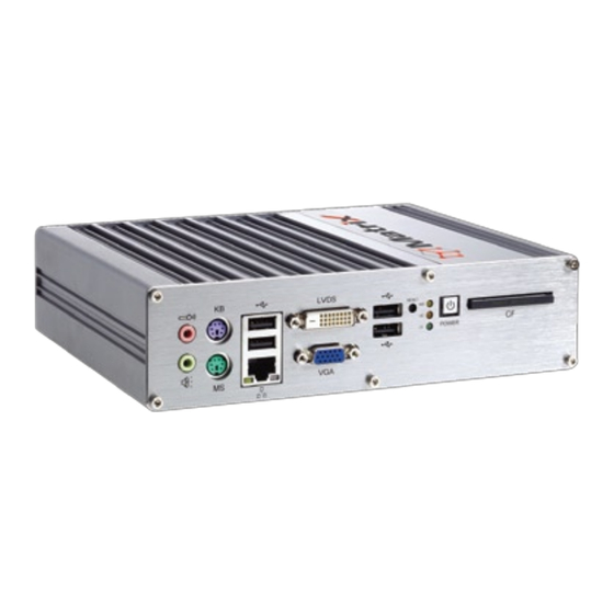
Matrix MXE-1200 Series User’s Manual 2.2 Front Panel I/O Connectors Each of the MXE-1200 series controllers have the same I/O con- nector configuration on the front panel. This section describes the functions of these I/O connectors. A. CompactFlash Socket B. Power Button C. -
Page 20: Compactflash Socket
User’s Manual 2.2.1 CompactFlash Socket The Matrix MXE-1200 series is equipped with a Type I Compact- Flash socket which is located on the front panel. The CF interface is transferred from SATA by an ASIC, and can be an alternative storage device for system installation. -
Page 21: Reset Button
Matrix MXE-1200 Series User’s Manual 2.2.4 Reset Button The reset button is used to perform hard reset for MXE-1200 con- troller. 2.2.5 LVDS Connector The LVDS connector is a DVI type to connect the MXE-1200 series controller to a LVDS interface monitor. The connector pin... -
Page 22: Vga Connector
Matrix MXE-1200 Series User’s Manual 2.2.6 VGA connector The VGA connector is used to connect the MXE-1200 series con- troller to a VGA interface (D-sub 15P) monitor. 2.2.7 USB 2.0 connectors The MXE-1200 series controller provides four USB 2.0 ports in Type A USB connectors on the front panel. -
Page 23: Table 2-3: Active/Link Led
Matrix MXE-1200 Series User’s Manual Active/Link LED LED Color Status Description Ethernet port is disconnected Ethernet port is connected and no data transmission Yellow Ethernet port is connected and is transmitting/receiv- Flashing ing data. Table 2-3: Active/Link LED Speed LED... -
Page 24: Keyboard & Mouse Ps2 Connectors
Matrix MXE-1200 Series User’s Manual 2.2.9 Keyboard & Mouse PS2 connectors The MXE-1200 controller provides connectors for connecting PS2 keyboard and mouse. The green connector is for a PS/2 mouse and the purple one is for a PS/2 keyboard. 2.2.10... -
Page 25: Rear Panel I/O Connectors
Matrix MXE-1200 Series User’s Manual 2.3 Rear Panel I/O Connectors The MXE-1200 series controller has the same I/O connector con- figurations on the rear panel. The entire MXE-1200 series control- ler has DC power input connector, Antenna connector and 12x COM ports (four D-sub 9P connectors of COM10-COM4 and one D-sub 62P connector of COM5-COM12). -
Page 26: Com Ports
Matrix MXE-1200 Series User’s Manual 2.3.2 COM Ports The MXE-1200 series controller provides 12 COM ports on the rear panel in the form of four D-sub 9P and one D-sub 62P con- nectors. The MXE-1200 series controller (MXE-1212/232, MXE- 1212/422, and MXE-1212/485) provides different RS232/RS422/ RS485 serial port options as shown in the following list. -
Page 27: Table 2-5: D-Sub 9P Com1 And Com2 Ports Signal Names
Matrix MXE-1200 Series User’s Manual Signal Name RS-232 RS-422 RS-485 DCD# TX422n 485n RXD# TX422p 485p TXD# RX422p DTR# RX422n DSR# RTS# CTS# Table 2-5: D-sub 9P COM1 and COM2 Ports Signal Names Signal Name RS-232 DCD# RXD# TXD# DTR#... -
Page 28: Table 2-7: D-Sub 62P Signal Names
Matrix MXE-1200 Series User’s Manual Pin Signal Name Pin Signal Name DGND DTR0 DTR4 DSR1 DCD1 DSR5 DCD5 DTR2 DTR6 DSR3 DGND DCD3 DTR7 DSR4 CTS0 DCD4 RTS0 DGND DTR5 CTS1 RTS1 DSR6 CTS2 DCD6 RTS2 DGND DSR7 CTS3 DCD7... -
Page 29: Antenna Connector
Matrix MXE-1200 Series User’s Manual Signal Name RS-232 RS-422 RS-485 DCD# TX422n 485n RXD# TX422p 485p TXD# RX422p DTR# RX422n DSR# RTS# CTS# Table 2-8: D-sub 9P COM5-COM12 Ports of the D-sub 62P Signal Names 2.3.3 Antenna connector The MXE-1200 series controller provides a SMA type antenna connector which preparing for WiFi or 3.5G module of internal... -
Page 30: Internal I/O Connectors
Matrix MXE-1200 Series User’s Manual 2.4 Internal I/O Connectors This section describes the internal I/O connectors of the MXE- 1200 controller. The figure shown below is a picture of the inside of the MXE-1200 series. A. SATA connector B. Pin head connector for LPT port and USB C. -
Page 31: Sata Connector
Matrix MXE-1200 Series User’s Manual 2.4.1 SATA Connector The MXE-1200 series controller provides a SATA port of Gen.1 (1.5 Gbit/s) speed. The SATA host controller supports two modes of operation, the legacy mode using I/O space and AHCI mode using memory space. This SATA connector is designed for install- ing a 2.5 inches hard disk drive (HDD) or solid state disk (SSD). -
Page 32: Connector For Lpt Port & Usb
Matrix MXE-1200 Series User’s Manual 2.4.2 Connector for LPT Port & USB The CN21 is a proprietary 26-pin connector which provides both LPT and USB functions. It’s designed to internally connect a LPT or USB device, such as a LPT or USB dongle, inside the chassis. -
Page 33: Clear Cmos Jumper
Matrix MXE-1200 Series User’s Manual 2.4.3 Clear CMOS Jumper When encountering the abnormal condition that causes the MXE- 1200 controller failed to boot, you can try to clear the BIOS content stored in CMOS and restore to the default setting. To clear CMOS, please shorten pin#2 and pin#3 of JP1 and then restore to normal mode (short pin#1 and pin#2). - Page 34 Matrix MXE-1200 Series User’s Manual System Description...
-
Page 35: Getting Started
Matrix MXE-1200 Series User’s Manual Getting Started This chapter demonstrates how to install the hard drive and Com- pactFlash card into system. Additional COM ports jumper settings and MXE-1200 series wall-mount installation are also discussed. 3.1 Installing a hard disk drive Before installing a hard disk drive, user should remove the front panel, rear panel, and bottom chassis first. - Page 36 Matrix MXE-1200 Series User’s Manual 2. Unscrew all the six screws on the rear panel and remove the panel. 3. Remove the bottom shell by sliding it off the chassis. Getting Started...
- Page 37 Matrix MXE-1200 Series User’s Manual 4. After removing the bottom chassis, the MXE-1200 series SBC with an empty HDD bracket fixed on it is exposed. Use a screw driver to unscrew 4 screws to remove the HDD bracket. Getting Started...
- Page 38 Matrix MXE-1200 Series User’s Manual 5. Four M3 screws are found as accessories in the pack- age. Fasten the four screws to attach your 2.5” HDD or SSD to the bracket. Getting Started...
- Page 39 Matrix MXE-1200 Series User’s Manual 6. Install the 2.5” HDD or SSD by gently push the HDD/ SSD connector (plug) into the SATA connector (recepta- cle) on the PCB. 7. Fasten the four screws to attach the HDD bracket to the copper nuts.
- Page 40 Matrix MXE-1200 Series User’s Manual 8. Put the bottom chassis back by sliding it on the chassis. 9. Screw in the 12 screws (M3 hex bolts) on the front and rear panels. Getting Started...
-
Page 41: Installing A Compactflash Card
Matrix MXE-1200 Series User’s Manual 3.2 Installing a CompactFlash Card The MXE-1200 series controller provides a CompactFlash socket on the front panel to accommodate a CF card as a replacement of hard disk drive. You can also install a SATA hard disk drive and CF card simultaneously and set the boot device preferences in BIOS. - Page 42 Matrix MXE-1200 Series User’s Manual 2. Align with the guide of CF socket and push the CF card to the bottom of the CF socket. Getting Started...
- Page 43 Matrix MXE-1200 Series User’s Manual The DC power input connector of the MXE-1200 series controller is located on the rear panel. It has three pins, V+, chassis ground, and V- from right to left respectively. The DC power input accepts an input voltage as shown in the specification mentioned in the earlier chapter.
-
Page 44: Mounting The Mxe-1200 Using The Wall-Mount Kit
Matrix MXE-1200 Series User’s Manual 3.3 Mounting the MXE-1200 Using the Wall-mount The MXE-1200 series controller is shipped with a VESA 100 wall- mount bracket. The bracket has four M4 mounting holes with a pitch of 100 mm so you attach it to any VESA 100 compatible mounting mechanism. - Page 45 Matrix MXE-1200 Series User’s Manual 2. Fasten the four screws to attach the bracket to where the MXE-1200 series controller is to be mounted (a wall or a monitor as in this photo). Getting Started...
- Page 46 Matrix MXE-1200 Series User’s Manual 3. Find the four specially-made screws for mounting in the screw pack. Fasten these 4 screws into the holes on the bottom of MXE-1200 series controller. Getting Started...
- Page 47 Matrix MXE-1200 Series User’s Manual 4. Join the screws on the bottom of chassis and the key holes on the bracket. Getting Started...
- Page 48 Matrix MXE-1200 Series User’s Manual 5. Push the MXE-1200 series controller down until there is a click to lock the chassis to the mounting bracket. Getting Started...
-
Page 49: Cooling Considerations
Matrix MXE-1200 Series User’s Manual 3.4 Cooling Considerations The hot components of MXE-1200 series controller (such as CPU, North Bridge and South Bridge) are all placed on the top side of PCB. These components are in direct contact to the aluminum top cover via thermal pads. - Page 50 Matrix MXE-1200 Series User’s Manual Getting Started...
-
Page 51: Bios Settings And Driver Installation
Matrix MXE-1200 Series User’s Manual BIOS Settings and Driver Installation 4.1 BIOS Setting The Basic Input/Output System (BIOS) is a program that provides a basic level of communication between the processor and periph- erals. In addition, the BIOS also contains codes for various advanced features applied to the MXE-1200 controller. -
Page 52: Advanced
Matrix MXE-1200 Series User’s Manual 4.1.2 Advanced 4.1.2.1 CPU Configuration Hyper Threading Technology This option allows you to Enable/Disable Hyper-Threading Technology. Intel® SpeedStep™ Tech This option enables or disables Intel SpeedStep™ technology. 4.1.2.2 IDE Configuration ATA/IDE Configuration This option specifies whether the IDE channels should be ini- tialized in Compatible Mode or Enhanced Mode. -
Page 53: Table 4-1: Parallel Port Modes
Matrix MXE-1200 Series User’s Manual 4.1.2.3 SuperIO Configuration Serial Port1/ Port2/ Port3/ Port4 Address These four options specify the base I/O port address of serial port1 to serial port4. Note: Do not set the same value for different serial ports to avoid resource conflict. - Page 54 Matrix MXE-1200 Series User’s Manual 4.1.2.5 Remote Access Configuration This option allows a remote access by another computer to get POST messages and send commands through serial port access. Remote Access Select this option to Enable or Disable the BIOS remote access feature.
-
Page 55: Table 4-2: Redirection After Bios Post
Matrix MXE-1200 Series User’s Manual Redirection after BIOS POST This option allows you to set Redirection configuration after BIOS POST. Available options are Disabled, Boot Loader, and Always. Option Description Disabled Turn off the redirection after POST. Boot Loader Activate the redirection during POST and Boot Loader. -
Page 56: Table 4-3: Suspend Mode
Matrix MXE-1200 Series User’s Manual 4.1.2.6 ACPI Configuration Suspend Mode This setting specifies either S1 (POS) or S3 (STR) system sus- pend mode. The Optimal and Fail-Safe Default setting is S3 (STR). Option Description Power On Suspend - Maintain current system status,... -
Page 57: Table 4-5: Legacy Usb Support
Matrix MXE-1200 Series User’s Manual RTC Alarm Date (Days) This option appears when Resume On RTC Alarm select Enabled. Please key in [+] or [-] to select, options are “Every Day” and “1”~”31”, indicate the alarm generate days. RTC Alarm Time This option appears when Resume On RTC Alarm select Enabled. - Page 58 Matrix MXE-1200 Series User’s Manual BIOS EHCI hand-off This option provides a workaround for OSes without ECHI hand-off support. The change of EHCI ownership should be claimed by the EHCI driver. USB Mass Storage Device Configuration This is a submenu for configuring the USB Mass Storage Class Devices which are in use on the USB ports found by BIOS.
-
Page 59: Chipset
Matrix MXE-1200 Series User’s Manual 4.1.3 Chipset 4.1.3.1 North Bridge Configuration DRAM Frequency Specify DRAM frequency. You can specify whether to let the BIOS set theDRAM frequency automatically or configure it manually (400 MHz or 533 MHz). Configure DRAM Timing by SPD Specify Enable to allow the timing setting of the DRAM to be configured from the SPD or Disable to configure it manually. -
Page 60: Table 4-6: Dvmt Mode Select
Matrix MXE-1200 Series User’s Manual DVMT Mode Select Dynamic Video Management Technology (DVMT) allows addi- tional system memory to be dynamically allocated in operating system for graphics usage. Once the application is closed, the allocated memory is released and is then available for system usage. -
Page 61: Table 4-7: Restore On Power Loss
Matrix MXE-1200 Series User’s Manual 4.1.3.2 South Bridge Configuration USB Function Specify the number of USB ports enabled in Matrix controller. The default value is 8 USB ports. USB 2.0 Controller Specify whether to enable or disable built-in USB 2.0 controller in south bridge chip. -
Page 62: Security
Matrix MXE-1200 Series User’s Manual 4.1.4 Security The Security setup menu provides both a Supervisor and a User password. If you use both passwords, the Supervisor password must be set first. To uninstall the passwords, you can simply set a NULL password. -
Page 63: Boot
Matrix MXE-1200 Series User’s Manual Virus Boot Protection This option appears after specifying Supervisor password. Option Description Disabled The BIOS will not protect the boot sector from a virus. Enabled The BIOS will protect the boot sector from a virus. - Page 64 Matrix MXE-1200 Series User’s Manual 4.1.5.2 Boot Device Priority Specify the priority of boot devices. All installed boot devices are detected during POST and displayed on the screen. You can refer to the following steps to specify different boot device.
-
Page 65: Exit
Matrix MXE-1200 Series User’s Manual Boot from USB external hard drive 1. Select USB Drives and press Enter. 2. Your USB external hard drive is displayed with its identi- fication string. Specify it as 1st Drive. 3. Go back to upper level and select your USB external hard drive in 1st Boot Device. -
Page 66: Driver Installation
Matrix MXE-1200 Series User’s Manual 4.2 Driver Installation After installing the operating system, you need to install all related drivers to make your system work accordingly. This section describes the drivers needed for Windows operating systems and the procedures to install them. For other OS support, please con- tact ADLINK for further information. -
Page 67: Install The Chipset Driver
Matrix MXE-1200 Series User’s Manual 4.2.1 Install the Chipset Driver This section describes the procedure to install the chipset driver of MXE-1200 series. The chipset driver outlines to the operating sys- tem how to configure the Intel® 945GSE chipset components in... -
Page 68: Install The Graphics Driver
Matrix MXE-1200 Series User’s Manual 4.2.2 Install the Graphics Driver This section describes the procedure to install the graphics driver of MXE-1200 series. The MXE-1200 series is equipped with Intel® GMA950 graphics media accelerator integrated in Intel Mobile Intel® 945GSE chipset. The Intel® Graphics Media Accelerator... -
Page 69: Install The Ethernet Driver
Matrix MXE-1200 Series User’s Manual 4.2.3 Install the Ethernet Driver This section describes the procedure to install the Ethernet driver of MXE-1200 series controller. Please follow the steps to install the driver for Realtek 8111C Gigabit Ethernet controller. For Windows 2000 and XP users: 1. -
Page 70: Install The Audio Driver
Matrix MXE-1200 Series User’s Manual 4.2.4 Install the Audio Driver This section describes the procedure to install the audio driver of MXE-1200 series. The MXE-1200 controller supports Intel High Definition audio using Realtek ALC262 chip, which provides up to 24-bit, 192Kbps high quality audio input/output. Please follow the following steps to install audio driver for MXE-1200 series. -
Page 71: Appendix
Matrix MXE-1200 Series User’s Manual Appendix A.1 Watchdog Timer (WDT) Function Reference This appendix describes the usage of the watchdog timer (WDT) function library for the MXE-1200 controller. Watchdog timer is a hardware mechanism to reset the system in case the operating system or an application halts. - Page 72 Matrix MXE-1200 Series User’s Manual InitWDT @ Description Initialize the watchdog timer function of MXE-1200 controller. InitWDT must be called before the invocation of any other WDT function. @ Supported controllers MXE-1200 @ Syntax C/C++ BOOL InitWDT() @ Parameters None @ Return code TRUE if watchdog timer is successfully initialized.
- Page 73 Matrix MXE-1200 Series User’s Manual SetWDT @ Description Set the timeout value of watchdog timer. There are two param- eters for this function to indicate the timeout ticks and unit. Users should call ResetWDT or StopWDT before the expiration of watchdog timer, or the system will be reset.
- Page 74 Matrix MXE-1200 Series User’s Manual StartWDT @ Description Start the watchdog timer function. Once the StartWDT is invoked, the countdown of watchdog timer starts. Users should call ResetWDT or StopWDT before the expiration of watchdog timer, or the system will be reset.
- Page 75 Matrix MXE-1200 Series User’s Manual ResetWDT @ Description Reset the watchdog timer. The invocation of ResetWDT allows users to restore the watchdog timer to the initial timeout value specified in SetWDT function. Users should call ResetWDT or StopWDT before the expiration of watchdog timer, or the sys- tem will be reset.
- Page 76 Matrix MXE-1200 Series User’s Manual StopWDT @ Description Stop the watchdog timer. @ Supported controllers MXE-1200 @ Syntax C/C++ BOOL StopWDT() @ Parameters None @ Return codes TRUE if watchdog timer is successfully stopped. FALSE if watchdog timer is failed to stop.
Need help?
Do you have a question about the Matrix MXE-1200 Series and is the answer not in the manual?
Questions and answers