
Subscribe to Our Youtube Channel
Related Manuals for ADLINK Technology MXE-211


Summary of Contents for ADLINK Technology MXE-211
- Page 1 MXE-210 Series MXE-211/MXE-212 Fanless Embedded Computer User’s Manual Manual Rev.: Nov. 30, 2017 Revision Date: 50-1Z242-1000 Part No: Leading EDGE COMPUTING...
-
Page 2: Revision History
Leading EDGE COMPUTING Revision History Revision Release Date Description of Change(s) Nov. 30, 2017 Initial Release... - Page 3 MXE-210 Series Preface Copyright 2017 ADLINK Technology, Inc. This document contains proprietary information protected by copy- right. All rights are reserved. No part of this manual may be repro- duced by any mechanical, electronic, or other means in any form without prior written permission of the manufacturer.
- Page 4 Leading EDGE COMPUTING Conventions Take note of the following conventions used throughout this manual to make sure that users perform certain tasks and instructions properly. Additional information, aids, and tips that help users perform tasks. NOTE: NOTE: Information to prevent minor physical injury, component dam- age, data loss, and/or program corruption when trying to com- plete a task.
-
Page 5: Table Of Contents
MXE-210 Series Table of Contents Preface ..................iii List of Tables................xi List of Figures ..............xiii 1 Introduction ................ 1 Features................2 Specifications............... 3 Mechanical Drawings............5 Front Panel I/O Connectors ..........8 1.4.1 Power Button .............. 8 1.4.2 LED Indicators ............ - Page 6 Leading EDGE COMPUTING 1.5.12 Internal Speaker Wafer (Optional) ......22 1.5.13 Internal MIC-IN & HP-OUT Wafer (Optional).... 23 Adapters and Other Accessories ........23 2 Getting Started ..............25 Unpacking Checklist ............25 Installing Mini-PCIe Devices ..........25 Installing Mini-PCIe mSATA Module........29 Installing Mini-PCIe WiFi Module ........
- Page 7 MXE-210 Series Turbo Mode ..............49 Critical Trip Point ............50 Passive Cooling Trip Point ..........50 A.2.2 Graphics Configuration..........50 GTT Size ............... 50 Aperture Size ..............50 DVMT Pre-Allocated ............. 50 DVMT Total Gfx Mem ........... 51 A.2.3 Onboard Device Configuration .........
- Page 8 Leading EDGE COMPUTING Port ................61 A.2.7 TPM Configuration............ 62 Security Device Support ..........62 A.2.8 Network Stack Configuration ........63 Network Stack ............... 63 A.2.9 System Management..........64 Flags ................68 Power Up ..............69 A.2.10 Miscellaneous ............70 OS Selection ..............
- Page 9 MXE-210 Series Discard Changes ............77 Restore Defaults ............77 Save as User Defaults ..........77 Restore User Defaults ..........77 Launch EFI Shell from filesystem device ...... 77 Important Safety Instructions ..........79 Getting Service..............83 Table of Contents...
- Page 10 Leading EDGE COMPUTING This page intentionally left blank. Table of Contents...
-
Page 11: List Of Tables
MXE-210 Series List of Tables Table 1-1: LED Operation Indicators ........... 9 Table 1-2: DisplayPort Pin Assignment ........10 Table 1-3: Gigabit Ethernet Port LED Function ......11 Table 1-4: DB-9P COM Port Pin Assignment ......13 Table 1-5: Internal I/O Legend........... 16 Table 1-6: HSUART Interface Wafer Pin Definitions .... - Page 12 Leading EDGE COMPUTING This page intentionally left blank. List of Tables...
-
Page 13: List Of Figures
MXE-210 Series List of Figures Figure 1-1: MXE-210 Functional Block Diagram......5 Figure 1-2: Top View..............6 Figure 1-3: Front View ..............6 Figure 1-4: (Right) Side View............7 Figure 1-5: (Left) Side View ............7 Figure 1-6: Front Panel I/O ............8 Figure 1-7: DB-9P COM Port ............ - Page 14 Leading EDGE COMPUTING This page intentionally left blank. List of Figures...
-
Page 15: Introduction
MXE-210 Series Introduction ADLINK’s new Matrix MXE-210 Series compact embedded plat- form, based on the Intel® Atom x7-E3950/X5-E3930 processor, delivers the most reliable I/O design for maximum connectivity, and a full aluminum alloy enclosure with industry-class construc- tion makes it the embedded system of choice for industrial auto- mation applications demanding... -
Page 16: Features
Leading EDGE COMPUTING vibration resistance, and optionally available extended operating temperature ranges of -20°C to 70°C and -40°C to 85°C. The MXE-210 Series maximizes manageability and security for a world of applications, delivering efficient remote monitoring of sys- tem activity and health in real time via different security building blocks, such as hardware-based root integrity protection and soft- ware-based prevention of unauthorized software and malware takeover, system control over a robust secured channel, and com-... -
Page 17: Specifications
MXE-210 Series 1.2 Specifications MXE-211 MXE-212 System Core ® Intel® Atom X7-E3950 Intel Atom X5-E3930 Processor Chipset Video 1 x DisplayPort 1.2 (supports DP++) 2 GB DDR3L 1600 MHz SODIMM module Memory (Up to 8 GB support) I/O Interface Ethernet... - Page 18 Leading EDGE COMPUTING MXE-211 MXE-212 Extended -20°C to 70°C Operating (with optional industrial mSATA/SATA SSD) Temperature Ultra- -40°C to 85°C Extended (with optional industrial Operating mSATA/SATA SSD and heat Temperature spreader kit) Storage -40°C to 85°C (excl. HDD/MicroSD) Temperature Humidity Approx.
-
Page 19: Mechanical Drawings
MXE-210 Series Channel 0 DDI0 DDR3L 1600MT/s DisplayPort SO -DIMM 0 connector PCIe X1 LAN0 MDI Intel GbE I210 RJ45 & USB3.0x2 USB3.0 x 2 connector SLB9665 XT2.0 PCIe X1 LAN1 MDI Intel GbE Wafer to DI/O RJ45 & USB 2.0x2 I210 USB2.0x2 connector... -
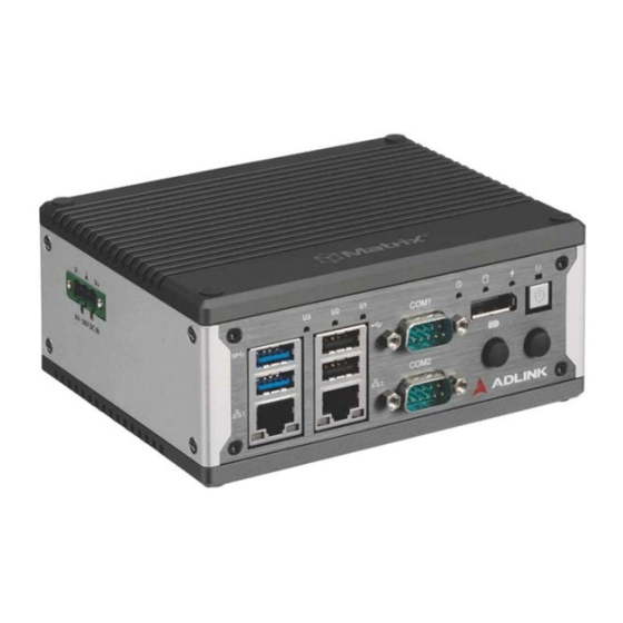
Page 20: Figure 1-2: Top View
Leading EDGE COMPUTING Figure 1-2: Top View Figure 1-3: Front View Introduction... -
Page 21: Figure 1-4: (Right) Side View
MXE-210 Series Figure 1-4: (Right) Side View Figure 1-5: (Left) Side View Introduction... -
Page 22: Front Panel I/O Connectors
Leading EDGE COMPUTING 1.4 Front Panel I/O Connectors The following lists I/O connectors located on the front panel of the MXE-210, as labeled. Figure 1-6: Front Panel I/O Power button Reset button Antenna port DP connector LED operation indicators (x3) ... -
Page 23: Led Indicators
MXE-210 Series 1.4.2 LED Indicators In addition to the LED of the power button, three LEDs on the front panel indicate the following operations. Indicator Color Description Indicates watchdog timer status. Flashes when Watchdog (WDT) Yellow watchdog timer starts, and when timer is expired, system will auto-reboots. -
Page 24: Table 1-2: Displayport Pin Assignment
Leading EDGE COMPUTING cable and Display Port cable, with DP1.2 support for resolutions up to 4096 x 2160 at 60Hz. Pin Signal Pin Signal ML_Lane0_P 11 GND 12 ML_Lane3_N ML_Lane0_N 13 Config1 ML_Lane1_P 14 Config2 15 Aux_P ML_Lane1_N 16 GND ML_Lane2_P 17 Aux_N 18 Hot Plug... -
Page 25: Dual Gigabit Ethernet Ports
MXE-210 Series 1.4.5 Dual Gigabit Ethernet Ports TTwo Gigabit Ethernet ports on the front panel support the Intel i210IT GbE controller, which provides: IEEE 802.3az Energy Efficient Ethernet IEEE 1588/802.1AS precision time synchronization IEEE 802.3av traffic shaper Interrupt moderation, VLAN support, IP checksum offload ... -
Page 26: Usb 3.0 Port
Leading EDGE COMPUTING 1.4.6 USB 3.0 Port The USB 3.0 port supports Type A connection, compatible with SuperSpeed, Hi-Speed, full-speed and low-speed USB devices, with support for multiple boot devices, including USB flash, USB external HDD, and USB CD-ROM drivers and boot priority and boot device configured in BIOS. -
Page 27: Dc Power Supply Connector
MXE-210 Series Signal DSR# RTS# CTS# Table 1-4: DB-9P COM Port Pin Assignment 1.4.8 DC Power Supply Connector Located on the left side panel of the MXE-210. Introduction... -
Page 28: Internal I/O Connectors
Leading EDGE COMPUTING 1.5 Internal I/O Connectors Figure 1-8: Mainboard Top View Introduction... -
Page 29: Figure 1-9: Mainboard Underside View
MXE-210 Series Figure 1-9: Mainboard Underside View USB2.0 internal dongle (CN21) RTC Battery Header (CN_BAT) Internal Speaker Wafer (Optional) (CN8) Internal MIC-IN & HP-OUT Wafer (Optional) (CN6) Extended reset wafer (CN27) Internal I2C Interface Wafer (CN20) Extended power wafer (CN26) Internal SATA Interface Wafer (CN32) Micro SD card socket (CN31) USIM slot (CN15) -
Page 30: Internal Hsuart Interface Wafer
Leading EDGE COMPUTING mSATA slot (CN5) Internal HSUART Interface Wafer (CN22) DDR3L SO-DIMM slot (CN1) Table 1-5: Internal I/O Legend 1.5.1 Internal HSUART Interface Wafer HSUART signal and +3.3V power are provided by the connector with cable. Signal +3.3V SOC_UART1_RX_CON SOC_UART1_TX_CON SOC_UART1_CTS_CON-L SOC_UART1_RTS_CON-L... -
Page 31: Internal Usb2.0 Interface Wafer
MXE-210 Series 1.5.3 Internal USB2.0 Interface Wafer Signal SOC_USB2_D6_P SOC_USB2_D6_N +3.3V USB2_WAFER-L Table 1-7: USB2.0 Interface Wafer Pin Definitions 1.5.4 Internal I2C Interface Wafer I2C and +3.3V/+5V power by this connector with cable. are pro- vided by the connector with cable. Signal SOC_I2C1_CLK Introduction... -
Page 32: Clear Cmos Jumper
Leading EDGE COMPUTING Signal SOC_I2C1_DAT +3.3V Table 1-8: Internal I2C Interface Wafer Pin Definitions 1.5.5 Clear CMOS Jumper Under conditions in which the MXE-210 fails to boot, clearing the BIOS content stored in CMOS and restoring the default settings may be effective. To clear CMOS, short Pin 1 and Pin 2 of CN24 and remove the jumper, after which the CMOS will be restored to factory default settings. -
Page 33: Gps Antenna Power Header
MXE-210 Series 1.5.6 +5V GPS Antenna Power Header External +5V power is reserved for GPS antenna power, with +5V provided by this connector with cable. Signal Table 1-10: +5V GPS Antenna Power Connector Pin Definition 1.5.7 Internal SATA Interface Wafer Reserved for extended 2.5”... -
Page 34: Extended Power Wafer
Leading EDGE COMPUTING Signal Signal SOC_SATA_TX1_P_C SOC_SATA_TX1_N_C SOC_SATA_RX1_N_C SOC_SATA_RX1_P_C +3.3V +3.3V +3.3V Table 1-11: SATA Wafer Pin Definition 1.5.8 Extended Power Wafer Providing internal connectors for the power button. Signal PWR_BTN_CN-L Table 1-12: Extended Power Header Connector Pin Definition Introduction... -
Page 35: Internal I2C Interface Wafer
MXE-210 Series 1.5.9 Internal I2C Interface Wafer Provides the I2C signal and +3.3V power with cable. Signal +3.3V SOC_I2C0_DAT SOC_I2C0_CLK SOC_I2C0_INT Table 1-13: I2C Box Header Connector Pin Definition 1.5.10 Extended Reset Wafer Provides internal connectors for the reset button. Introduction... -
Page 36: Rtc Battery Header
Leading EDGE COMPUTING Signal RESET_BTN_CN-L Table 1-14: Extended Reset Header Connector Pin Definition 1.5.11 RTC Battery Header Links to the 3V coin battery pack for system RTC function. Signal P_+3V3_VBAT Table 1-15: RTC Battery Connector Pin Definition 1.5.12 Internal Speaker Wafer (Optional) Provides the audio speaker signal, supporting 2x 2W8Ω... -
Page 37: Internal Mic-In & Hp-Out Wafer (Optional)
MXE-210 Series Signal SPKR_L_P SPKR_L_N SPKR_R_P SPKR_R_N Table 1-16: Speaker Wafer Pin Definition 1.5.13 Internal MIC-IN & HP-OUT Wafer (Optional) Provides MIC-IN and HP-OUT signals with cable. Signal EX_MIC_CN HP_CN_L HP_CN_R AGND_AUDIO Table 1-17: MIC-IN & HP-OUT Wafer Pin Definition 1.6 Adapters and Other Accessories Device adaptors and other optional accessories should only be obtained through your ADLINK dealer. - Page 38 Leading EDGE COMPUTING This page intentionally left blank. Introduction...
-
Page 39: Getting Started
MXE-210 Series Getting Started 2.1 Unpacking Checklist Before unpacking, check the shipping carton for any damage. If the shipping carton and/or contents are damaged, inform your dealer immediately. Retain the shipping carton and packing materials for inspection. Obtain authorization from your dealer before returning any product to ADLINK. - Page 40 Leading EDGE COMPUTING Getting Started...
- Page 41 MXE-210 Series Getting Started...
- Page 42 Leading EDGE COMPUTING 2. Remove the chassis underside. Getting Started...
-
Page 43: Installing Mini-Pcie Msata Module
MXE-210 Series 2.3 Installing Mini-PCIe mSATA Module 1. Insert the mini-PCIE mSATA module into the slot at an angle Getting Started... - Page 44 Leading EDGE COMPUTING 2. Depress the mini-PCI-E mSATA module until seated and fix with two 2 M2.5-P-head-L5 screws. 3. Replace the chassis underside. Getting Started...
-
Page 45: Installing Mini-Pcie Wifi Module
MXE-210 Series 2.4 Installing Mini-PCIe WiFi Module 1. Insert the mini-PCIE WiFi module into the slot at an angle Getting Started... - Page 46 Leading EDGE COMPUTING 2. Depress the module until seated and fix with two 2 M2.5- P-head-L5 screws. 3. Replace the chassis underside. Getting Started...
-
Page 47: Installing Mini-Pcie 3G/4G Lte Module
MXE-210 Series 2.5 Installing Mini-PCIE 3G/4G LTE Module Use of the mini-PCIE 3G/4G LTE module requires installation of a SIM card. 1. Remove the remaining two screws from the right side panel and remove the panel. 2. Insert the SIM card into the slot. Getting Started... - Page 48 Leading EDGE COMPUTING 3. Insert the mini-PCIE 3G/4G LTE module into the slot at an angle 4. Replace the side panel and chassis underside. Getting Started...
-
Page 49: Connecting Dc Power
MXE-210 Series 2.6 Connecting DC Power Before providing DC power to the MXE-210, ensure the volt- age and polarity provided are compatible with the DC input. Improper input voltage and/or polarity can be responsible for WARNING: system damage. Active DC power sources must comply with LPS and SELV cir- cuits with no energy hazard, as well as the following. - Page 50 Leading EDGE COMPUTING 2. Use the 2 included M4-F head screws to fix the DIN rail bracket to the chassis, according to the spacing dimen- sions of the screw holes and brackets, as shown. Getting Started...
- Page 51 MXE-210 Series 97.28 86.08 53.92 49.65 Getting Started...
-
Page 52: Wall Mounting
Leading EDGE COMPUTING 2.8 Wall Mounting While configuration shown may indicate otherwise, due to the presence of antenna ports, for safety, the device should ONLY be wall-mounted with the front and rear panels on the sides, CAUTION: NEVER on the top or underside. Use the 2 M4 screws shipped with the controller to fix the 2 wall- mount brackets, also included, to the chassis, according to the spacing dimensions of the screw holes and brackets. -
Page 53: Cooling Considerations
MXE-210 Series 182.40 2.9 Cooling Considerations Heat-generating components of the MXE-210 (such as CPU and PCH) are all situated on the left side of the system. These compo- nents directly contact the heat sink via thermal pads and dissipate heat generated by the components. To maximize efficiency of heat dissipation, maintain a minimum of 2 inches (5cm) clearance on the top of the MXE-210. - Page 54 Leading EDGE COMPUTING This page intentionally left blank. Getting Started...
-
Page 55: Driver & Application Installation
MXE-210 Series Driver & Application Installation After installing the operating system, all related drivers must be installed for the system to function properly. This section describes the drivers needed for Windows operating systems and the procedures to install them. For other OS support, please contact ADLINK for further information. -
Page 56: Installing The Graphics Driver
Leading EDGE COMPUTING To install the chipset driver for the MXE-210 1. Close any running applications. 2. From ADLINK's website, download Windows 10 IoT Enterprise drivers for the MXE-210. 3. Execute Setup.exe and follow onscreen instructions to complete the setup. 4. -
Page 57: Installing The Usb 3.0 Driver
MXE-210 Series 3.4 Installing the USB 3.0 Driver To install the driver for the USB 3.0 controller: 1. Close any running applications. 2. From ADLINK's website, download Windows 10 IoT Enterprise drivers for the MXE-210. 3. Launch setup.exe and follow onscreen instructions to complete the setup. - Page 58 Leading EDGE COMPUTING To install the SEMA utility, WDT and DI/O drivers: 1. Close any running applications. From ADLINK's website, download Windows 10 IoT Enterprise drivers for the MXE-210. 2. Execute Setup.exe and follow onscreen instructions to complete the setup. After installation is complete, reboot the system.
-
Page 59: A Appendix: Bios Setup
MXE-210 Series Appendix A BIOS Setup BIOS options in the manual are for reference only, and are subject to configuration. Users are welcome to download the latest BIOS version from the ADLINK website. NOTE: NOTE: The Basic Input/Output System (BIOS) is a program that provides a basic level of communication between the processor and peripherals. -
Page 60: Main
Leading EDGE COMPUTING A.1 Main A.1.1 BIOS Information Shows current system BIOS core version, BIOS version and Board version. A.1.2 System Time/System Date Changes system time and date. Highlight System Time or System Date using the up or down <Arrow> keys. Enter new values using the keyboard then <Enter>. -
Page 61: Board Information
MXE-210 Series The time is in 24-hour format, for example, 5:30 A.M. appears as 05:30:00, and 5:30 P.M. as 17:30:00. NOTE: NOTE: A.1.3 Board Information Displays serial number, manufacturing date, last repair date, and MAC ID. As well, Runtime Statistics are listed, including total run- time, current runtime, power cycles, boot cycles, and boot reason. -
Page 62: Advanced
Leading EDGE COMPUTING A.2 Advanced Setting incorrect or conflicting values in Advanced BIOS Setup may cause system malfunction. CAUTION: BIOS Setup... -
Page 63: Cpu Configuration
MXE-210 Series A.2.1 CPU Configuration Active Processor Cores Number of cores to enable in each processor package. Intel Virtualization Technology When enabled, allows a VMM to utilize the additional hardware capabilities provided by Vanderpool Technology VT-d Enables/disables CPU VT-d Turbo Mode Enables/disables Turbo Mode. -
Page 64: Critical Trip Point
Leading EDGE COMPUTING Critical Trip Point Temperature threshold of the Critical Trip Point. Passive Cooling Trip Point Temperature threshold of the Passive Cooling Trip Point. A.2.2 Graphics Configuration GTT Size Sets GTT size Aperture Size Sets aperture size DVMT Pre-Allocated Sets size of DVMT 5.0 pre-allocated (fixed) graphics memory used by internal graphics device BIOS Setup... -
Page 65: Dvmt Total Gfx Mem
MXE-210 Series DVMT Total Gfx Mem Sets size of DVMT5.0 total graphic memory used by internal graphics device A.2.3 Onboard Device Configuration COM1 Control Selects COM1 mode from among RS232, RS422, and RS485. COM2 Control Selects COM2 mode from among RS232, RS422, and RS485. HSUART Enables/disables LPSS HSUART support. -
Page 66: Lan #1 (Intel I210)
Leading EDGE COMPUTING LAN #1 (Intel I210) Enables/disables LAN device #1. LAN #2 (Intel I210) Enables/disables LAN device #2. Realtek Audio Support Enables/disables Realtek audio device. Serial Console Redirection COM 1 Console Redirection Enables/Disables COM 1 console redirection. BIOS Setup... -
Page 67: Console Redirection Settings (Com 1)
MXE-210 Series Console Redirection Settings (COM 1) Terminal Type Emulation: ANSI: Extended ASCII char set. VT100: ASCII char set. VT100+: Extends VT100 to support color, function keys, etc. VT-UTF8: Uses UTF8 encoding to map Unicode chars onto 1 or more bytes. Bits per second Selects serial port transmission speed, which must be matched on the other side, where long or noisy lines may require lower... - Page 68 Leading EDGE COMPUTING Data Bits Number of data bits Parity Parity bit can be sent with data bits to detect transmission errors, where Even: parity bit is 0 if the number of 1's in the data bits is even Odd: parity bit is 0 if number of 1's in the data bits is odd. Mark: parity bit is always 1.
- Page 69 MXE-210 Series Legacy OS Redirection Resolution In legacy OS, the number of rows and columns supporting redi- rection Putty KeyPad Selects FunctionKey and KeyPad on PuTTY Redirection After BIOS Post When Bootloader is selected, Legacy Console Redirection is disabled before booting to legacy OS. When Always Enable is selected, Legacy Console Redirection is enabled for legacy OS.
-
Page 70: Console Redirection
Leading EDGE COMPUTING COM 2 Console Redirection Enables/Disables COM 2 console redirection. Console Redirection Settings (COM 2) Terminal Type Emulation: ANSI: Extended ASCII char set. VT100: ASCII char set. VT100+: Extends VT100 to support color, function keys, etc. VT-UTF8: Uses UTF8 encoding to map Unicode chars onto 1 or more bytes. - Page 71 MXE-210 Series Bits per second Selects serial port transmission speed, which must be matched on the other side, where long or noisy lines may require lower speeds. Data Bits Number of data bits Parity Parity bit can be sent with data bits to detect transmission errors, where Even: parity bit is 0 if the number of 1's in the data bits is even Odd: parity bit is 0 if number of 1's in the data bits is odd.
- Page 72 Leading EDGE COMPUTING Recorder Mode When enabled, only text will be sent, to capture terminal data. Resolution 100x31 Enables/disables extended terminal resolution Legacy OS Redirection Resolution In legacy OS, the number of rows and columns supporting redi- rection Putty KeyPad Selects FunctionKey and KeyPad on PuTTY Redirection After BIOS Post When Bootloader is selected, Legacy Console Redirection is...
-
Page 73: Advanced Power Management
MXE-210 Series A.2.4 Advanced Power Management Power Supply Unit ATX: OS will turn off system power when shutdown, where AT mode does not support S3 & S4. State After G3 Specifies state to enter when power is re-applied after a power failure (G3 state). -
Page 74: Lan #1 Wake
Leading EDGE COMPUTING LAN #1 Wake Enables/disables onboard Wake on LAN for #1 LAN #2 Wake Enables/disables onboard Wake on LAN for #2 A.2.5 USB Configuration XHCI Hand-off A workaround for OS without XHCI handoff support, where XHCI ownership change should be claimed by the XHCI driver. USB Mass Storage Driver Support Enables/disables USB mass storage driver support. -
Page 75: Usb Transfer Time-Out
MXE-210 Series USB transfer time-out Timeout value for Control, Bulk, and Interrupt transfers. Device reset time-out USB mass storage device Start Unit command timeout. Device power-up delay Maximum time the device will take before reporting to the Host Controller, where Auto uses default value, for a Root port 100 ms, and for a Hub port the delay is taken from the Hub descriptor. -
Page 76: Tpm Configuration
Leading EDGE COMPUTING A.2.7 TPM Configuration Security Device Support Enables/disables BIOS support for security device, when enabled, OS will not show the security device, and TCG EFI protocol and INT1A interface will not be available. BIOS Setup... -
Page 77: Network Stack Configuration
MXE-210 Series A.2.8 Network Stack Configuration Network Stack Enables/disables UEFI network stack BIOS Setup... -
Page 78: System Management
Leading EDGE COMPUTING A.2.9 System Management Shows SEMA firmware and bootloader versions and build dates. BIOS Setup... - Page 79 MXE-210 Series SEMA Features Shows features supported by the SEMA version. BIOS Setup...
- Page 80 Leading EDGE COMPUTING Temperatures Shows current CPU temperature, and current, startup, mini- mum, and maximum board temperatures. BIOS Setup...
- Page 81 MXE-210 Series Power Consumption Shows current input current and power, as well as system volt- ages. BIOS Setup...
-
Page 82: Flags
Leading EDGE COMPUTING Flags Shows BMC flags with exception codes. BIOS Setup... -
Page 83: Power Up
MXE-210 Series Power Up Lists Power-Up Watchdog status. BIOS Setup... -
Page 84: Miscellaneous
Leading EDGE COMPUTING A.2.10 Miscellaneous OS Selection Allows selection of active OS. BIOS Setup... -
Page 85: Intel® I210 Gigabit Network Connection
MXE-210 Series A.2.11 Intel® I210 Gigabit Network Connection Blink LEDs Identifies the physical network port by flashing the associated LED. BIOS Setup... -
Page 86: Nic Configuration
Leading EDGE COMPUTING A.2.12 NIC Configuration Link Speed Specifies the port speed used for the selected boot protocol. Wake On LAN Enables server power-up using an in-band magic packet. BIOS Setup... -
Page 87: Security
MXE-210 Series A.3 Security If only the Administrator’s password is set, only access to Setup is limited and authorization requested only when enter- ing Setup. If only the User’s password is set, a password must NOTE: NOTE: be entered to boot or enter setup. In Setup the user has Admin- istrator rights. -
Page 88: Secure Boot
Leading EDGE COMPUTING A.3.1 Secure Boot Shows System Mode and Secure Boot status. Secure Boot is activated when Platform Key (PK) is enrolled, where System Mode is User/Deployed, and CSM function is disabled. NOTE: NOTE: BIOS Setup... -
Page 89: Boot
MXE-210 Series A.4 Boot Setup Prompt Timeout Number of seconds to wait for setup activation key, with 65535(0xFFFF) indicating infinite wait. Bootup NumLock State Sets keyboard NumLock status Quiet Boot Enables/disables Quiet Boot option Fast Boot Enables/disables boot with the minimal device initialization required to launch active boot option, with no effect on BBS boot options. -
Page 90: Boot Option Priorities
Leading EDGE COMPUTING Sets number of seconds to wait for setup activation key. Boot Option Priorities Specifies the priority of boot devices, with all installed boot devices detected during POST and displayed, where selecting Boot Option # specifies the desired boot device. A.5 Save &... -
Page 91: Save Changes And Reset
MXE-210 Series Save Changes and Reset Resets the system after saving changes. Discard Changes and Reset Resets system setup without saving any changes. Save Changes Saves changes to any setup options. Discard Changes Discards changes to any of the setup options. Restore Defaults Restores/loads default values for all setup options. - Page 92 Leading EDGE COMPUTING This page intentionally left blank. BIOS Setup...
-
Page 93: Important Safety Instructions
MXE-210 Series Important Safety Instructions For user safety, please read and follow all instructions, Warnings, Cautions, and Notes marked in this manual and on the associated device before handling/operating the device, to avoid injury or damage. S'il vous plaît prêter attention stricte à tous les avertissements et mises en garde figurant sur l'appareil , pour éviter des blessures ou des dommages. - Page 94 Leading EDGE COMPUTING Never attempt to repair the device, which should only be serviced by qualified technical personnel using suitable tools A Lithium-type battery may be provided for uninterrupted backup or emergency power. Risk of explosion if battery is replaced with one of an incorrect type;...
- Page 95 MXE-210 Series BURN HAZARD Touching this surface could result in bodily injury. To reduce risk, allow the surface to cool before touching. RISQUE DE BRÛLURES Ne touchez pas cette surface, cela pourrait entraîner des blessures. Pour éviter tout danger, laissez la surface refroidir avant de la toucher.
- Page 96 Leading EDGE COMPUTING This page intentionally left blank. Important Safety Instructions...
-
Page 97: Getting Service
San Jose, CA 95138, USA Tel: +1-408-360-0200 Toll Free: +1-800-966-5200 (USA only) Fax: +1-408-360-0222 Email: info@adlinktech.com ADLINK Technology (China) Co., Ltd. 300 Fang Chun Rd., Zhangjiang Hi-Tech Park Pudong New Area, Shanghai, 201203 China Tel: +86-21-5132-8988 Fax: +86-21-5132-3588 Email: market@adlinktech.com...
Need help?
Do you have a question about the MXE-211 and is the answer not in the manual?
Questions and answers