Table of Contents
Advertisement
Quick Links
Advertisement
Table of Contents

Related Manuals for ADLINK Technology MXC-6600 Series


Summary of Contents for ADLINK Technology MXC-6600 Series
- Page 1 MXC-6600 Series High Performance 9th Generation Intel® Xeon®/Core™ i7/i3 & 8th Gen Intel® Core™ i5 Processor-Based Fanless Expandable Computer MXC-6620/MXC-6640 User’s Manual Manual Rev.: Sept. 14, 2020 Revision Date: 50-1Z330-1000 Part No: Leading EDGE COMPUTING...
- Page 2 Leading EDGE COMPUTING Revision History Revision Release Date Description of Change(s) 2020-09-14 Initial release...
- Page 3 MXC-6600 Series Preface Copyright © 2020 ADLINK Technology Inc. This document contains proprietary information protected by copy- right. All rights are reserved. No part of this manual may be repro- duced by any mechanical, electronic, or other means in any form without prior written permission of the manufacturer.
- Page 4 Leading EDGE COMPUTING California Proposition 65 Warning WARNING: This product can expose you to chemicals including acrylamide, arsenic, benzene, cadmium, Tris(1,3-dichloro-2-propyl) phosphate (TDCPP), 1,4- Dioxane, formaldehyde, lead, DEHP, styrene, DINP, BBP, PVC, and vinyl materials, which are known to the State of California to cause cancer, and acrylamide, benzene, cadmium, lead, mercury, phthalates, toluene, DEHP, DIDP, DnHP, DBP, BBP, PVC, and vinyl materials, which are known to the State of California to cause...
-
Page 5: Table Of Contents
Packing List ................. 2 Optional Accessories ............2 2 Specifications ..............3 MXC-662X/MXC-664X/MXC-6621/MXC-6641 ....3 MXC-6622/MXC-6642/MXC-6623/MXC-6643 ..... 5 MXC-6600 Series Functional Block Diagram ...... 7 Display Options..............8 Mechanical Dimensions............9 3 System Layout..............15 Front Panel ................ 15 Internal I/O Connectors............26 4 Getting Started .............. - Page 6 Leading EDGE COMPUTING Main ................... 40 Advanced ................41 Chipset................56 Security ................67 Boot ................... 69 Save & Exit ................ 71 C Appendix: Watchdog Timer (WDT) Function Library ..73 WDT with API/Windows ............. 73 WDT with DOS/Linux ............76 D Appendix: Digital Input/Output Function Library ...79 Important Safety Instructions..........
-
Page 7: List Of Tables
MXC-6600 Series List of Tables Table 2-1: Maximum Display Resolution Configurations ..... 8 Table 3-1: Front Panel I/O Legend ..........15 Table 3-2: LED Indicators ............16 Table 3-3: DisplayPort Pin Definition ......... 17 Table 3-4: Applicable Cable Types..........18 Table 3-5: Digital Input/Output Connector Pin Definition ... - Page 8 Leading EDGE COMPUTING This page intentionally left blank. viii List of Tables...
-
Page 9: List Of Figures
MXC-6600 Series List of Figures Figure 2-1: MXC-6600 Series Functional Block Diagram ....7 Figure 2-2: MXC-6620 Front View ............. 9 Figure 2-3: MXC-6640 Front View ........... 10 Figure 2-4: MXC-6620/6640 Left Side View........11 Figure 2-5: MXC-6620/6640 Right Side View ........12 Figure 2-6: MXC-6620/6640 Top View (with wall-mount brackets).. - Page 10 Leading EDGE COMPUTING This page intentionally left blank. List of Figures...
-
Page 11: Introduction
(Gen3) expansion slots accept a variety of PCI, PCIe x8, and PCIe x16 add-on cards for platform development operations. Compared to other industrial PCs, the MXC-6600 Series is more compact and reliable with superior dependability in harsh environments where severe temperature variation and vibration may occur. The... -
Page 12: Packing List
Retain the shipping carton and packing mate- rials for inspection. Obtain authorization from your dealer before returning any product to ADLINK. Ensure that the following items are included in the package. MXC-6600 Series Fanless Embedded Computer Accessory Box DC power jack Wall-mount brackets Screw pack 1.4 Optional Accessories... -
Page 13: Specifications
MXC-6600 Series Specifications 2.1 MXC-662X/MXC-664X/MXC-6621/MXC-6641 MXC-662X MXC-664X MXC-6621 MXC-6641 System Core Processor Intel® Xeon® E-2276ME 45W Intel® Core™ i7-9850HE 45W Chipset Mobile Intel® CM246 Memory 4GB DDR4 2400MHz, dual SODIMMs, up to 32GB I/O Interface Display 2x DP++, 1x HDMI... - Page 14 Leading EDGE COMPUTING MXC-662X MXC-664X MXC-6621 MXC-6641 Mounting Wall mount Power Supply DC Input 9-32V DC (± 10% tolerance) AC Input Optional: 220W/280W AC/DC adapter Environmental Standard: 0°C to 50°C (32°F to 122°F) w/ airflow Operating Extended: (w/ ind. storage, airflow) Temperature -20°C to 70°C (-4°F to 158°F) (w/ single SODIMM) -20°C to 60°C (-4°F to 140°F) (w/ dual SODIMMs)
-
Page 15: Mxc-6622/Mxc-6642/Mxc-6623/Mxc-6643
MXC-6600 Series 2.2 MXC-6622/MXC-6642/MXC-6623/MXC-6643 MXC-6622 MXC-6642 MXC-6623 MXC-6643 System Core Processor Intel® Core™ i5-8400H 45W Intel® Core™ i3-9100HL 25W Chipset Mobile Intel® CM246 Memory 4GB DDR4 2400MHz, dual SODIMMs, up to 32GB I/O Interface Display 2x DP++, 1x HDMI Expansion... - Page 16 Leading EDGE COMPUTING MXC-6622 MXC-6642 MXC-6623 MXC-6643 AC Input Optional: 220W/280W AC/DC adapter Environmental Standard: 0°C to 50°C (32°F to 122°F) w/ airflow Operating Extended: (w/ ind. storage, airflow) Temperature -20°C to 70°C (-4°F to 158°F) (w/ single SODIMM) -20°C to 60°C (-4°F to 140°F) (w/ dual SODIMMs) Storage -40°C to 85°C (-40°F to 185°F) excluding storage Temperature...
-
Page 17: Mxc-6600 Series Functional Block Diagram
2 USB 2 and 2 USB 2/USB 3 SMBus BIOS board GPI/O 8DI/8DO CN (Cable) DP (Colay with DDI2) C CN x2 TPM 2.0 UART(cable) 2x D-sub (RS232/422/485) UART(cable) FAN CN 2x D-sub (RS232) NCT6106D UART(cable) 2x D-sub (RS232) optional Figure 2-1: MXC-6600 Series Functional Block Diagram... -
Page 18: Display Options
Leading EDGE COMPUTING 2.4 Display Options With computing and graphic performance enhancement from its 8th & 9th Generation Intel processors, the MXC-6600 Series con- troller can support three independent displays, with configurations as follows. DisplayPort1 Display Option 1 4096x2304@60Hz DisplayPort2... -
Page 19: Mechanical Dimensions
MXC-6600 Series 2.5 Mechanical Dimensions (units: mm) Figure 2-2: MXC-6620 Front View... -
Page 20: Figure 2-3: Mxc-6640 Front View
Leading EDGE COMPUTING (units: mm) 5.20 Figure 2-3: MXC-6640 Front View... -
Page 21: Figure 2-4: Mxc-6620/6640 Left Side View
MXC-6600 Series (units: mm) Figure 2-4: MXC-6620/6640 Left Side View... -
Page 22: Figure 2-5: Mxc-6620/6640 Right Side View
Leading EDGE COMPUTING (units: mm) Figure 2-5: MXC-6620/6640 Right Side View... -
Page 23: Figure 2-6: Mxc-6620/6640 Top View (With Wall-Mount Brackets)
MXC-6600 Series (units: mm) Figure 2-6: MXC-6620/6640 Top View (with wall-mount brackets) - Page 24 Leading EDGE COMPUTING This page intentionally left blank.
-
Page 25: System Layout
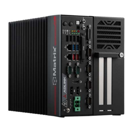
MXC-6600 Series System Layout 3.1 Front Panel The MXC-6600 Series provides the following front panel access features. Figure 3-1: Front Panel I/O DC Power Input Extend Power Button DisplayPort x2 J Power HDMI K Reset USB 3.1 Gen 2 (Type-A) x2... -
Page 26: Table 3-2: Led Indicators
Leading EDGE COMPUTING 3.1.2 LED Indicators In addition to the LED of the power button, three LEDs on the front panel indicate the following. LED Indicator Color Description Indicates watchdog timer status. When watchdog Watchdog Yellow timer starts, the LED flashes. When the timer is (WD) expired, the system will auto reboot. -
Page 27: Table 3-3: Displayport Pin Definition
Two PCI Express x4 slots support expansion with standard PCIe Gen3 cards and full PCI express x4 signals. 3.1.6 Reset Button The reset button executes a hard reset for the MXC-6600 Series. 3.1.7 DisplayPort Connectors Two DisplayPort connectors on the front panel can connect to... -
Page 28: Table 3-4: Applicable Cable Types
30-01157-0020 Active DisplayPort to DVI adapter cable Table 3-4: Applicable Cable Types 3.1.8 Digital I/O Connector The MXC-6600 Series provides 8 channels of non-isolation digital input and 8 channels of non-isolation digital output circuits, with the following specifications. 8-channel Digital Input VIH: 2 to 5.25V... -
Page 29: Table 3-5: Digital Input/Output Connector Pin Definition
MXC-6600 Series Signal Signal Signal Signal Table 3-5: Digital Input/Output Connector Pin Definition Figure 3-4: Digital Input Circuit... -
Page 30: Table 3-6: Hdmi Connector Pin Definition
Leading EDGE COMPUTING Figure 3-5: Digital Output Circuit 3.1.9 HDMI Connector The MXC-6600 Series provides one HDMI connector for connec- tion to an external monitor. Pin # Signal Pin # Signal CON_HDMI_TX2_P CON_HDMI_TX2_N CON_HDMI_TX1_P CON_HDMI_TX1_N CON_HDMI_TX0_P CON_HDMI_TX0_N CON_HDMI_CLK_P CON_HDMI_CLK_N DVI_SCL_SINK... - Page 31 BIOS. 3.1.11 USB 3.1 Ports The MXC-6600 Series provides two USB 3.1 Gen 2 and two USB 3.1 Gen 1 ports supporting Type-A USB 3.1 connection on the front panel. All USB 3.1 ports are compatible with super-speed Gen 1, high-speed, full-speed and low-speed USB devices, except USB 3.1 port #1 &...
-
Page 32: Table 3-7: Ethernet Port Pin Definition
Leading EDGE COMPUTING Speed LED Active/Link Green/Orange Yellow Figure 3-6: Ethernet Port and LEDs 10BASE-T/ Pin # 1000BASE-T 100BASE-TX LAN_TX0+ LAN_TX0- LAN_TX1+ — LAN_TX2+ — LAN_TX2- LAN_TX1- — LAN_TX3+ — LAN_TX3- Table 3-7: Ethernet Port Pin Definition LED Color Status Description Ethernet port is disconnected. -
Page 33: Table 3-10: Dc Power Input Pin Definition
MXC-6600 Series 3.1.13 DC Power Input Figure 3-7: DC Power Input Signal V+ (DC_IN) V- (DGND) Table 3-10: DC Power Input Pin Definition Refer to Section 4.1: Attach DC Power Connector on page 33 to install the DC Power Connector to the DC Power Input. -
Page 34: Table 3-11: D-Sub 9-Pin Signal Function Of Com Ports
Leading EDGE COMPUTING 3.1.14 COM Port Connectors The MXC-6600 Series provides six COM ports through D-sub 9- pin connectors. The COM1 & COM2 ports support RS-232/422/ 485 modes by BIOS setting, while COM3 through COM6 support only RS-232. Figure 3-8: COM Port Pin Definition... -
Page 35: Figure 3-9: Cfast Host Slot
MXC-6600 Series 3.1.15 CFast Host Slot The MXC-6600 Series is equipped with a Type II Push-Push CFast host slot on the front panel, by SATA interface. Data trans- fer rates up to 3.0Gb/s (300MB/s) are supported. The host SATA controller provides a legacy operating mode using I/O space, and an AHCI operating mode using memory space. -
Page 36: Internal I/O Connectors
Leading EDGE COMPUTING 3.2 Internal I/O Connectors 3.2.1 Mainboard Connector Locations Figure 3-10: Mainboard Connectors... -
Page 37: Table 3-12: Mainboard Connector Legend
MXC-6600 Series Fan connector SATA connector1 SATA connector2 USB 2.0 dongle BP slot BP slot For MXM card power wafer FM board to board connector CFast connector Battery socket DDR4 slot M.2 connector Sim card socket by M.2 Sim card socket by Mini PCIe... -
Page 38: Table 3-13: 2-Slot Backplane Board Connector Legend
Leading EDGE COMPUTING 3.2.2 2-slot Backplane Connector Locations MXC-662X, MXC-6621, MXC6622, MXC-6623 Figure 3-11: 2-slot Backplane Board Connectors USB 2.0 dongle connector SATA power connector SATA signal connector PCI Express x4 slot PCI Express x16 slot Additional power for PCIe x16 slot (12V and 5V) Direct SATA connector Table 3-13: 2-slot Backplane Board Connector Legend... -
Page 39: Table 3-14: 4-Slot Backplane Board Connector Legend
MXC-6600 Series 3.2.3 4-slot Backplane Connector Locations MXC-664X, MXC-6641, MXC-6642, MXC-6643 Figure 3-12: 4-slot Backplane Board Connectors SATA power SATA signal Additional power for PCIe slot (12V) USB 2.0 dongle Direct SATA PCI slot PCIe x4 slot PCIe x16 slot... -
Page 40: Table 3-15: Gps Module Power Header Pin Definition
Leading EDGE COMPUTING 3.2.4 GPS Module Power Headers Power supply via cable for Mini PCIe GPS module cards (5V). Figure 3-13: GPS Module Power Header Pin Definition Signal +5V_GPS Table 3-15: GPS Module Power Header Pin Definition 3.2.5 USB 2.0 Connector One USB 2.0 Type-A connector is provided on the mainboard for internal USB dongle, with another on the backplane board. -
Page 41: Table 3-16: 12V Fan Connector Pin Definition
MXC-6600 Series 3.2.8 12V Fan Connector DC 12V fan module power supply is provided through the connec- tor, to which the optional fan module connects when installed in the chassis. Figure 3-14: 12V Fan Connector Pin Definition Signal FAN_GND P_+12V_FAN... -
Page 42: Table 3-17: Pwr/Reset Header Pin Definition
Leading EDGE COMPUTING 3.2.10 Extended PWR/RESET Header An internal header is provided for the Power and Reset buttons, with pin definition as shown. Figure 3-16: PWR/RESET Header Pin Definition Signal PWR_BTN-L RESET_BTN-L Table 3-17: PWR/RESET Header Pin Definition 3.2.11 USIM Slot The USIM slot connects to the Mini PCIe and M.2 slots. -
Page 43: Getting Started
MXC-6600 Series Getting Started 4.1 Attach DC Power Connector Locate the DC power connector shown below that is included in the Accessory Box. Insert it into the DC Power Input “A” shown in Figure 3-1 on page 15 and secure it to the chassis using the cap- tive screws. -
Page 44: Mounting The Mxc-6600 Series
Leading EDGE COMPUTING 4.2 Mounting the MXC-6600 Series 4.2.1 Install the Wall-mount Brackets Use the 6 M4 6mm screws included in the Accessory Box to attach the 2 included wall-mount brackets to the chassis as indi- cated by the red circles below. - Page 45 MXC-6600 Series Mounting the Device / Montage de l'Appareil Mount the device to a wall using the 4 keyhole openings indicated or the 6 mounting holes circled in red, according to the spacing dimensions of the holes in the bracket as shown in Figure 2-2 MXC-6620 Front View and Figure 2-3 MXC-6640 Front View.
-
Page 46: Driver Installation
Leading EDGE COMPUTING 4.3 Driver Installation Download the Windows 10 drivers for your system from the prod- uct page at https://www.adlinktech.com/Products/ Industrial_PCs_Fanless_Embedded_PCs/IntegratedFanlessEm- beddedComputers/MXC-6600_Series and install. The following drivers must be installed: Chipset Graphics Audio Ethernet Intel ME DI/O... -
Page 47: A Appendix: Power Consumption
MXC-6600 Series Appendix A Power Consumption Information in this Appendix is for power budget planning and design purposes only. Actual power consumption may differ based on final application. NOTE: NOTE: A.1 Power Consumption Reference Power consumption as follows is based on lab data in which 24V DC is applied and current is measured by the DC power supply. - Page 48 Leading EDGE COMPUTING Sufficient power supply for the entire system is required to meet these specifications. At least 100W at 24V input is recommended. NOTE: NOTE: Heat generated by add-on PCI/PCIe adapters affects thermal stability. Additional heat dissipa- tion is required when the system operates at high temperatures or in harsh environments with add-on adapters.
-
Page 49: B Appendix: Bios Setup
MXC-6600 Series. Most users do not need to use the BIOS setup program, as the MXC-6600 Series ships with default settings that work well for most configurations. Enter BIOS setup by pressing <DEL> when the system is powered on and the POST (power-on self-test) message is displayed. -
Page 50: Main
Leading EDGE COMPUTING B.1 Main Contains basic system information for the MXC-6600 Series. Changing BIOS settings may lead to incorrect controller behav- ior and possible inability to boot. In such a case, Section 3.2.9:Clear CMOS Jumper provides instruction on WARNING:... -
Page 51: Advanced
The time is in 24-hour format. For example, 5:30 A.M. NOTE: NOTE: appears as 05:30:00, and 5:30 P.M. as 17:30:00. B.2 Advanced Setting incorrect or conflicting values in Advanced BIOS Setup may cause a system malfunction CAUTION: Accesses advanced options of the MXC-6600 Series. - Page 52 Leading EDGE COMPUTING B.2.1CPU Configuration...
- Page 53 MXC-6600 Series Hyper-Threading Enabled for Windows 7, 10 IoT Enterprise, and Linux (optimized for Hyper-Threading Technology). When Disabled only one thread per enabled core is enabled. Active Processor Cores Number of cores to enable in each processor package. Intel (VMX) Virtualization Technology When enabled, a VMM can utilize the additional hardware capabil- ities provided by Vanderpool Technology.
- Page 54 Leading EDGE COMPUTING B.2.2 Power Management State After G3 Specify what state to go to when power is re-applied after a power failure (G3 state). RTC Wake system from S5 Enables/Disables the system wake on alarm event. Select Fixed- Time, and the system will wake on the hr::min::sec specified. Select DynamicTime, the system will wake on the current time + Increase minute(s).
- Page 55 MXC-6600 Series B.2.3 Serial Console Configuration COM1 Console Redirection Enables/Disables SIO COM1 Console Redirection. Console Redirection Settings The settings specify how the host computer and the remote com- puter (which the user is using) will exchange data. Both computers should have the same or compatible settings.
- Page 56 Leading EDGE COMPUTING Console Redirection Settings The settings specify how the host computer and the remote com- puter (which the user is using) will exchange data. Both computers should have the same or compatible settings. COM SOL (Pci Bus0, Dev22.Fun3) Console Redirection Enables/Disables AMT PCI SOL Console Redirection.
- Page 57 MXC-6600 Series B.2.4 USB Configuration USB Mass Storage Driver Support Enables/Disables USB mass storage driver support. USB transfer time-out Timeout value for Control, Bulk, and Interrupt transfers. Device reset time-out USB mass storage device Start Unit command timeout. Device power-up delay...
- Page 58 Leading EDGE COMPUTING B.2.5 TPM 2.0 Configuration Security Device Support Enables/Disables BIOS support for security devices. The operat- ing system will not show the security device. The TCG EFI proto- col and INT1A interface will not be available. SHA-1 PCR Bank Enables/Disables SHA-1 PCR Bank.
- Page 59 MXC-6600 Series Pending operation Schedule an operation for the security device. The computer will reboot in order to change the state of the security device NOTE: NOTE: Platform Hierarchy Enables/Disables Platform Hierarchy. Storage Hierarchy Enables/Disables Storage Hierarchy. Endorsement Hierarchy Enables/Disables Endorsement Hierarchy.
- Page 60 Leading EDGE COMPUTING B.2.6 AMT Configuration AMT BIOS Features When disabled, AMT BIOS Features are no longer supported and the user is no longer able to access MEBx Setup. MEBx hotkey Pressed Enable automatic MEBx hotkey press.
- Page 61 MXC-6600 Series B.2.7 Onboard Devices Configuration COM1 Control Sets port type (RS-232/422/485) for COM1 serial port. COM2 Control Sets port type (RS-232/422/485) for COM2 serial port. LAN #1 (Intel I219) Enables/Disables onboard Intel I219 LAN controller. LAN #2 (Intel I211AT)
- Page 62 Leading EDGE COMPUTING B.2.8 NCT6106D HW Monitor NCT6106D HW Monitor Displays CPU/board temperatures, system fan speed and various voltages. System Fan Control Mode Sets the system fan control mode. T1 (Temperature 1), Range: 1-100 T1 Duty Set T1 related DC/PWM value, Range: 0-255...
- Page 63 MXC-6600 Series T2 (Temperature 2), Range: 1-100 T2 Duty Set T2 related DC/PWM value, Range: 0-255 T3 (Temperature 3), Range: 1-100 T3 Duty Set T3 related DC/PWM value, Range: 0-255 T4 (Temperature 4), Range: 1-100 T4 Duty Set T4 related DC/PWM value, Range: 0-255 BP Fan Control Mode Sets the BP fan control mode.
- Page 64 Leading EDGE COMPUTING T3 Duty Set T3 related DC/PWM value, Range: 0-255 T4 (Temperature 4), Range: 1-100 T4 Duty Set T4 related DC/PWM value, Range: 0-255...
- Page 65 MXC-6600 Series B.2.9 BIOS Watchdog Timer BIOS POST Watchdog Disable: Disables watchdog timer. Second Mode: Enables watchdog timer in seconds mode. Minute Mode: Enables watchdog timer in minutes mode.
-
Page 66: Chipset
Leading EDGE COMPUTING B.3 Chipset Setting incorrect or conflicting values in Chipset BIOS Setup may cause a system malfunction. CAUTION:... - Page 67 MXC-6600 Series B.3.1 System Agent (SA) Configuration System Agent (SA) Configuration Display and configure VT-d's capability and provide settings for memory, graphics and DMI/OPI configuration.
- Page 68 Leading EDGE COMPUTING B.3.1.1 Memory Configuration Memory Configuration Display memory speed, size, brand and configuration.
- Page 69 MXC-6600 Series B.3.1.2 Graphics Configuration Primary Display Selects which of the IGFX/PEG/PCH PCI(e) graphics devices should be the primary display. Select SG for Switchable Gfx. Internal Graphics Keep IGFX enabled based on the Setup options. GTT Size Sets GTT size.
- Page 70 Leading EDGE COMPUTING DVMT Pre-Allocated Sets size of DVMT 5.0 pre-allocated (fixed) graphics memory used by the internal graphics device. DVMT Total Gfx Mem Sets size of DVMT5.0 total graphic memory used by the internal graphics device. B.3.1.3 DMI/OPI Configuration DMI/OPI Configuration Display DMI link speed and width.
- Page 71 MXC-6600 Series B.3.2 PCH-IO Configuration PCH-IO Configuration Provides for SATA, Security and HD Audio configuration.
- Page 72 Leading EDGE COMPUTING B.3.2.1 SATA And RST Configuration SATA Mode Selection Determines how SATA controller(s) operate. SATA Controller Speed Sets the maximum speed the SATA controller can support. M.2 Storage Enables/Disables M.2 storage. CFast Card Enables/Disables CFast card. Hot Plug Designates selected port as hot pluggable.
- Page 73 MXC-6600 Series SATA HDD 1 Enables/Disables SATA HDD 1 SATA HDD 2 Enables/Disables SATA HDD 2 SATA HDD 3 Enables/Disables SATA HDD 4 SATA HDD 4 Enables/Disables SATA HDD 4...
- Page 74 Leading EDGE COMPUTING B.3.2.2 Security Configuration BIOS Lock Enable/Disable the PCH BIOS Lock Enable feature. Required to be enabled to ensure SMM protection of flash.
- Page 75 MXC-6600 Series B.3.2.3 HD Audio Configuration Audio Output Selection Selects the audio output device.
- Page 76 Leading EDGE COMPUTING B.3.2.4 BackPlane PCIe Configuration BackPlane PCIe Configuration Displays the BackPlane type, link speed and width. Speed Controls the PCIe maximum speed.
-
Page 77: Security
MXC-6600 Series B.4 Security If only the Administrator password is set, access s limited and the password requested on Setup. If User password is set, it acts as a power-on password and must be entered to boot or enter setup. In... - Page 78 Leading EDGE COMPUTING B.4.1 Secure Boot Menu Secure Boot Control The Secure Boot feature is Active if Secure Boot is enabled, Plat- form Key (PK) is enrolled and the system is in User mode. Chang- ing the system mode requires a platform reset.
-
Page 79: Boot
MXC-6600 Series B.5 Boot Setup Prompt Timeout Number of seconds before setup activation key is launched, with 65535(0xFFFF) setting an indefinite wait time. Bootup Num-Lock State Sets keypad Number Lock status following boot. Quiet Boot Option Description Disabled Directs BIOS to display POST messages Enabled Directs BIOS to display the OEM logo. - Page 80 Leading EDGE COMPUTING Fast Boot Option Description Disabled Directs BIOS to perform all POST tests. Directs BIOS to skip certain POST tests to boot Enabled faster. While enabling Fast Boot can reduce system ready time, some prerequisites can reduce effectiveness Boot mode select Sets legacy or UEFI boot mode.
-
Page 81: Save & Exit
MXC-6600 Series B.6 Save & Exit Save Changes and Exit Saves all changes before exiting Setup. Discard Changes and Exit Discards all changes and exits Setup. Save Changes and Reset Saves all changes and reboots the system with the new settings. - Page 82 Leading EDGE COMPUTING Discard Changes Discards all changes without exiting Setup. Restore Defaults Sets all BIOS options to default settings, designed for maximum system stability but less than maximum performance. Select Restore Defaults if the computer encounters system configuration problems. Save as User Defaults Save the current changes as user defaults.
-
Page 83: C Appendix: Watchdog Timer (Wdt) Function Library
Industrial_PCs_Fanless_Embedded_PCs/IntegratedFanlessEm- beddedComputers/MXC-6600_Series To use the WDT function library for the MXC-6600 Series, include the header file WDT.h and linkage library WDT.lib in the C++ proj- ect. InitWDT Initializes the watchdog timer function. Must be called before the invocation of any other WDT function. - Page 84 Leading EDGE COMPUTING SetWDT Sets the timeout value of the watchdog timer. There are two parameters for this function to indicate the timeout ticks and unit. ResetWDT or StopWDT should be called before the expi- ration of watchdog timer, or the system will reset. Syntax C/C++ BOOL SetWDT(BYTE tick, BYTE unit)
- Page 85 MXC-6600 Series Parameters None Return codes TRUE if watchdog timer is successfully started. FALSE if watchdog timer is failed to start. ResetWDT Reset the watchdog timer. The invocation of ResetWDT allows restoration of the watchdog timer to the initial timeout value specified in SetWDT function.
-
Page 86: Wdt With Dos/Linux
Leading EDGE COMPUTING C.2 WDT with DOS/Linux Under Linux, please program the WDT function using the LPC IO registers according to the sample program as follows. #include <dos.h> #include <stddef.h> #include <stdio.h> /* Config LPC IO NCT6102D to enter config mode */ EnterConfig(void) outp(0x4E, 0x87);... - Page 87 MXC-6600 Series printf("---------------------------------------------- ----\n"); EnterConfig(); /* config WDT registers */ w_reg(0x07,0x08); /* enable keyboard interrupt to reset WDT timeout value */ w_reg(0xF2,r_reg(0xF2)|0x40); /* set unit as second */ w_reg(0xF0,r_reg(0xF0)&~0x04); /* start the Watchdog */ w_reg(0x30,0x01); /* set timeout value as 30 seconds */ /* WDT start automatically while timeout value is set w_reg(0xF1,0x1E);...
- Page 88 Leading EDGE COMPUTING This page intentionally left blank.
-
Page 89: D Appendix: Digital Input/Output Function Library
Matrix DI/O API library files and a demo program (including source code) can be downloaded from http://www.adlinktech.com. To use the DI/O function library for the MXC-6600 Series, include the header file matrix_dio.h and linkage library matrix_dio.lib (matrix_dio64.lib for x64 operating systems) in the C++ project. - Page 90 Leading EDGE COMPUTING DI/O Functions ADMX_DIO_Init Initializes the DI/O function library. Syntax C/C++ short __stdcall ADMX_DIO_Init () Parameter(s) Return codes 0: NoError -13: ErrorOpenDriverFailed -200: ErrorDeviceIoctl ADMX_DIO_Close Closes the DI/O function library. Syntax C/C++ short __stdcall ADMX_DIO_Close () Parameter(s) Return codes 0: NoError...
- Page 91 C/C++ short __stdcall ADMX_DI_ReadPort(unsigned long* pwState) Parameter(s) pwState The state values of MXC-6600 Series digital input channels 1 to 8 (corresponding values 0 to 7) 1: Corresponding input/output line is HIGH 0: Corresponding input/output line is LOW Return codes 0: NoError...
- Page 92 __stdcall ADMX_DO_WritePort(unsigned long wState) Parameter(s) wState Sets the state values of MXC-6600 Series digital output chan- nels 1 to 8 (corresponding values 0 to 7) 1: Corresponding input/output line is HIGH 0: Corresponding input/output line is LOW Return codes...
- Page 93 C/C++ short __stdcall ADMX_DO_ReadPort(unsigned long* pwState) Parameter(s) pwState The state values of MXC-6600 Series digital output channels 1 to 8 (corresponding values 0 to 7) 1: Corresponding input/output line is HIGH 0: Corresponding input/output line is LOW Return codes 0: NoError...
- Page 94 Syntax C/C++ short __stdcall LED_Write(unsigned short wState) Parameter(s) wState Sets the state values of MXC-6600 Series LED channels 1 to 5 (corresponding values 0 to 4) 1: Corresponding input/output line is HIGH 0: Corresponding input/output line is LOW Return codes...
- Page 95 Syntax C/C++ short __stdcall LED_Read(unsigned short wState) Parameter(s) wState The state values of MXC-6600 Series LED channels 1 to 5 (corresponding values 0 to 4) 1: Corresponding input/output line is HIGH 0: Corresponding input/output line is LOW Return codes 0: NoError...
- Page 96 Leading EDGE COMPUTING This page intentionally left blank.
-
Page 97: Important Safety Instructions
MXC-6600 Series Important Safety Instructions For user safety, please read and follow all instructions, Warnings, Cautions, and Notes marked in this manual and on the associated device before handling/operating the device, to avoid injury or damage. Read these safety instructions carefully. - Page 98 Leading EDGE COMPUTING A Lithium-type battery may be provided for uninterrupted backup or emergency power. Risk of explosion if battery is replaced with one of an incorrect type; please dispose of used batteries appropriately. CAUTION: This equipment is not suitable for use in locations where children are likely to be present.
-
Page 99: Consignes De Sécurité Importante
MXC-6600 Series Consignes de Sécurité Importante S'il vous plaît prêter attention stricte à tous les avertissements et mises en garde figurant sur l'appareil, pour éviter des blessures ou des dommages. Lisez attentivement ces consignes de sécurité. Conservez le manuel de l'utilisateur pour pouvoir le con- sulter ultérieurement. - Page 100 Leading EDGE COMPUTING Si l'appareil ne doit pas être utilisé pendant de longues péri- odes, éteignez-le et débranchez-le de sa source d'alimenta- tion N'essayez jamais de réparer l'appareil, qui ne doit être réparé que par un personnel technique qualifié à l'aide d'outils appro- priés Une batterie de type Lithium peut être fournie pour une ali- mentation de secours ininterrompue ou d'urgence.
- Page 101 MXC-6600 Series RISQUE DE BRÛLURES Partie chaude! Ne touchez pas cette surface, cela pourrait entraîner des blessures. Pour éviter tout danger, laissez la surface refroidir avant de la toucher. Consignes de Sécurité Importante...
- Page 102 Leading EDGE COMPUTING This page intentionally left blank. Consignes de Sécurité Importante...
-
Page 103: Getting Service
San Jose, CA 95138, USA Tel: +1-408-360-0200 Toll Free: +1-800-966-5200 (USA only) Fax: +1-408-360-0222 Email: info@adlinktech.com ADLINK Technology (China) Co., Ltd. 300 Fang Chun Rd., Zhangjiang Hi-Tech Park Pudong New Area, Shanghai, 201203 China Tel: +86-21-5132-8988 Fax: +86-21-5132-3588 Email: market@adlinktech.com ADLINK Technology GmbH Hans-Thoma-Straße 11...
Need help?
Do you have a question about the MXC-6600 Series and is the answer not in the manual?
Questions and answers