
Related Manuals for ADLINK Technology MXE-1300 Series


Summary of Contents for ADLINK Technology MXE-1300 Series
- Page 1 MXE-1300 Series ® Intel Atom™ D2550/N2600 Fanless Embedded Computer with Integrated I/O 2.00 Manual Rev.: Sept 28, 2012 Revision Date: 50-1Z130-2000 Part No: Advance Technologies; Automate the World.
-
Page 2: Revision History
Revision History Revision Release Date Description of Change(s) 2.00 Sept 28, 2012 Initital Release... -
Page 3: Preface
MXE-1300 Preface Copyright 2012 ADLINK Technology, Inc. This document contains proprietary information protected by copy- right. All rights are reserved. No part of this manual may be repro- duced by any mechanical, electronic, or other means in any form without prior written permission of the manufacturer. - Page 4 Conventions Take note of the following conventions used throughout this manual to make sure that users perform certain tasks and instructions properly. Additional information, aids, and tips that help users perform tasks. NOTE: NOTE: Information to prevent minor physical injury, component dam- age, data loss, and/or program corruption when trying to com- plete a task.
-
Page 5: Table Of Contents
MXE-1300 Table of Contents Revision History..............ii Preface ..................iii List of Tables................ix List of Figures ................ xi 1 Introduction ................ 1 Overview................1 Features................2 Specifications............... 3 Unpacking Checklist ............5 Mechanical Drawings............6 Front Panel I/O Connectors ..........8 1.6.1 Power Button .............. - Page 6 1.8.1 SATA Slot ..............19 1.8.2 LVDS Interface Connector (optional)......19 1.8.3 Clear CMOS Jumper ..........20 1.8.4 LVDS Backlight Power Connector (option)....21 1.8.5 LVDS Voltage Selected Jumper (optional) ....22 1.8.6 Mini PCI Express Slot & USIM Socket...... 22 1.8.7 Extra +3.3 V/ +5 V Voltage Internal Connectors..
- Page 7 MXE-1300 GPO_Write() ..............47 GPO_Read() ..............47 B Appendix: BIOS Setup ............49 Main ................... 50 B.1.1 BIOS Information ............50 B.1.2 PC Health Status ............50 B.1.3 System Time/System Date ........50 Advanced................51 B.2.1 CPU Configuration............ 52 Hyper-Threading ............53 Execute Disable Bit ............
- Page 8 Out-of-Band Mgmt Port ..........58 Terminal Type ............... 58 Chipset................58 Primary IGFX Boot Display ........... 58 Active LFP ..............59 Boot ................... 59 Setup Prompt Timeout ..........59 Bootup Num-Lock State ..........59 Quiet Boot ..............59 Fast Boot ..............60 Boot Option Priorities ............
-
Page 9: List Of Tables
MXE-1300 List of Tables Table 1-1: MXE-1300 Front Panel I/O Connector Legend... 9 Table 1-2: LED Indicators ............9 Table 1-3: Active/Link LED ............12 Table 1-4: Speed LED ............... 12 Table 1-5: MXE-1300 Rear Panel I/O Connector Legend ..13 Table 1-6: D-sub 9P signal name of COM1 &... - Page 10 This page intentionally left blank. List of Tables...
-
Page 11: List Of Figures
MXE-1300 List of Figures Figure 1-1: MXE-1300 Functional Block Diagram......5 Figure 1-2: Top View..............6 Figure 1-3: Underside View ............7 Figure 1-4: Front View ..............7 Figure 1-5: Rear View ..............8 Figure 1-6: Side View..............8 Figure 1-7: Front Panel I/O ............ - Page 12 This page intentionally left blank. List of Figures...
-
Page 13: Introduction
MXE-1300 Introduction 1.1 Overview The Matrix MXE-1300 series is the latest addition to ADLINK’s ® Matrix line of embedded computers. Based on the Intel Atom™ D2550/N2600 processor, the MXE-1300 provides excellent com- puting performance while conserving considerable power. ® The three Intel... -
Page 14: Features
1.2 Features ® Intel Atom™ D2550/N2600 processor + NM10 chipset 2X Software-programmable RS-232/422/485 + 2 RS-232 ports 3X 1000/100/10 Mbps Ethernet ports, 6 USB 2.0 ports, 4 TTL digital input and output 1 external CF slot and 1 internal PCIe Mini Card socket with USIM slot Built-in 6 VDC to 36 VDC wide-range DC power input Rugged, -20°C to 70°C fanless operation (w/ industrial... -
Page 15: Specifications
MXE-1300 1.3 Specifications MXE-1301 MXE-1302 System Core Processor D2550 1.86GHz N2600 1.6GHz ® Chipset Intel NM10 Video DVI + VGA dual display up to 1920 x 1200 Up to 4 GB DDR3 Memory Up to 2 GB DDR3 800 800/1066 I/O Interface ®... - Page 16 MXE-1301 MXE-1302 Weight 1.8 kg (3.98 lb) Mounting VESA 100 Environmental Standard: 0°C to 50°C (32 to 122°F) (w/ HDD) Operating Extended: -20°C to 70°C (-14 to 140°F) (w/o HDD or Temperature w/ industrial SSD/CF) Storage -40°C to 85°C (-40 to 185°F) Temperature Humidity approx.
-
Page 17: Unpacking Checklist
MXE-1300 CRT Connector Intel Ⓡ Atom DDR3 Channel A D2550 1.86GHz DVI-D Connector 204 pin SODIMM level shifter 800/1066MHz Processor LVDS LVDS Internal Slot GbE I/F PCIe x1 SATA II GbE controller SATA RJ45 & Intel 82574L Connector USB x 2 USB 2.0 Connector SATA... -
Page 18: Mechanical Drawings
1.5 Mechanical Drawings All dimensions shown are in millimeters (mm) unless otherwise stated. NOTE: NOTE: Figure 1-2: Top View Introduction... -
Page 19: Figure 1-3: Underside View
MXE-1300 4x-M4 THREADED Figure 1-3: Underside View Figure 1-4: Front View Introduction... -
Page 20: Front Panel I/O Connectors
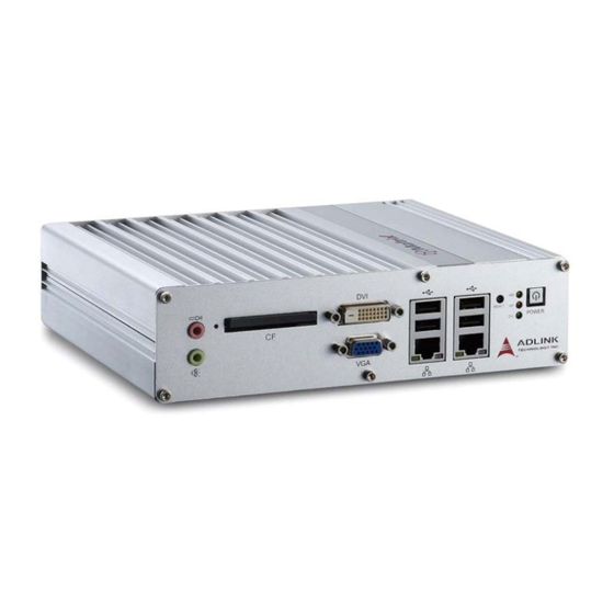
Figure 1-5: Rear View Figure 1-6: Side View 1.6 Front Panel I/O Connectors This section describes the I/O connectors lcoated on the front panel of the MXE-1300. Figure 1-7: Front Panel I/O Introduction... -
Page 21: Power Button
MXE-1300 Power Button LED Indicators Reset Button USB 2.0 connectors (Type A) Gigabit Ethernet connectors VGA connector DVI connector Compact-flash socket MIC & speaker jacks Table 1-1: MXE-1300 Front Panel I/O Connector Legend 1.6.1 Power Button The power button is a non-latched push button with a blue LED indicator. -
Page 22: Reset Button
1.6.3 Reset Button The reset button is used to perform hard reset for the MXE-1300. 1.6.4 VGA Connector The MXE-1300 provides one VGA connector for display on exter- nal (D-sub 15P) monitor. 1.6.5 DVI-D Connector The MXE-1300 provides one DVI-D connector for display on an external (DVI-D) monitor. -
Page 23: Gigabit Ethernet (Intel 82574L)
MXE-1300 powerup. For installation details, see “Installing a CF Card” on page 32.. 1.6.8 Gigabit Ethernet (Intel 82574L) The MXE-1300 provides two Gigabit Ethernet ports on the front panel, and one on the rear, via the Intel 82574L controller. The Ethernet controller supports the following features: Advanced error reporting Message signaled interrupts... -
Page 24: Mic & Speaker Jacks
Color Status Description Ethernet port is disconnected Ethernet port is connected and no Yellow data transmission is underway Ethernet port is connected and Flashing transmitting/receiving data. Table 1-3: Active/Link LED Color Status Description 10 Mbps Green/Orange Green 100 Mbps Orange 1000 Mbps Table 1-4: Speed LED 1.6.10... -
Page 25: Rear Panel I/O Connectors
MXE-1300 1.7 Rear Panel I/O Connectors Figure 1-9: Rear Panel I/O DC power supply connector COM port connectors (DB9 x4) USB 2.0 connectors (Type A) Gigabit Ethernet connector Digital I/O connector Antenna connector (optional) Table 1-5: MXE-1300 Rear Panel I/O Connector Legend 1.7.1 DC Power Supply Connector The DC power supply connector consists of three pins, V+, chas-... -
Page 26: Com Ports
Please ensure that DC power supply is within the input voltage range defined in the specification, stable and low-noise, and provides sufficient operating current. WARNING: Over- or under-voltage, unstable, or insufficiently powered DC power supply may cause system instability and physical dam- age. -
Page 27: Digital I/O Connector
MXE-1300 Signal name RS-232 RS-422 RS-485 RTS# CTS# Table 1-6: D-sub 9P signal name of COM1 & COM2 ports 1.7.3 Digital I/O Connector The MXE-1300 provides four channel non-isolation digital input circuits and four digital non-isolation output circuits through a ter- minal slot of pitch 3.81mm. -
Page 28: Table 1-7: Di/O Connector Pin Definition
Description Pin Description DI 0 DO 0 DI 1 DO 1 DI 2 DO 2 DI 3 DO 3 Table 1-7: DI/O Connector Pin Definition output MOSFET Introduction... -
Page 29: Antenna Connector
MXE-1300 Figure 1-11: DO Schematic +3.3V 4.7K MOSFET input Figure 1-12: DI Schematic 1.7.4 Antenna Connector The MXE-1300 provides two SMA type antenna connectors suit- able for Wireless LAN and Wireless WAN modules of an internal Mini PCI Express card. Introduction... -
Page 30: Internal I/O Connectors
1.8 Internal I/O Connectors Figure 1-13: Internal I/O A SATA slot F Mini PCI Express slot & USIM Socket B LVDS interface connector G Extra +3.3V voltage internal connector C Clear CMOS jumper H Extra +5V voltage internal connector LVDS backlight power Reset button extend internal connector connector LVDS voltage select... -
Page 31: Sata Slot
MXE-1300 1.8.1 SATA Slot The MXE-1300 provides a Gen 2 SATA port at 3.0 Gbit/s, compat- ible with SATA Gen 1 1.5Gbit/s. The SATA host controller sup- ports legacy mode using I/O space and AHCI mode using memory space. This SATA connector accepts 2.5” and 3.5” (optional) HDD or solid state disk (SSD). -
Page 32: Clear Cmos Jumper
Signal Signal +LVDS_VCC +LVDS_VCC LVDS_CLK+ LVDS_TXP2 LVDS_CLK- LVDS_TXN2 LVDS_TXP0 LVDS_TXP3 LVDS_TXN0 LVDS_TXN3 LVDS_TXP1 LVDS_DCLK LVDS_TXN1 LVDS_DDAT Table 1-9: LVDS Interface Connector Pin Definition 1.8.3 Clear CMOS Jumper Upon encountering an abnormal condition preventing the MXE-1300 from booting, the jumper can clear the BIOS content stored in CMOS and restore default settings. -
Page 33: Lvds Backlight Power Connector (Option)
MXE-1300 1.8.4 LVDS Backlight Power Connector (option) The MXE-1300 internal LVDS backlight power connector supports +5V and +12V, with numbering and pin definitions as follows. Figure 1-15: LVDS Backlight Power Connector Pin Numbering Description Backlight Enable Backlight Control +12V Table 1-11: LVDS Backlight Power Connector Pin Definition Introduction... -
Page 34: Lvds Voltage Selected Jumper (Optional)
1.8.5 LVDS Voltage Selected Jumper (optional) The MXE-1300 can support +3.3V and +5V for the LVDS power panel, with power of the LVDS interface (+LVDS_VCC) selected by internal jumper. default jumper setting is 5 V, as follows. +LVDS_VCC: +5V +LVDS_VCC: +3.3V Table 1-12: LVDS Voltage Selected Jumper 1.8.6 Mini PCI Express Slot &... -
Page 35: Reset/Power Button Extension Internal Connector
MXE-1300 Figure 1-16: +3.3 V/ +5 V Voltage Internal Connectors Pin Numbering Description +3.3V Table 1-13: +3.3 V/ +5 V Voltage Internal Connectors Pin Definition 1.8.8 Reset/Power Button Extension Internal Connector Internal reset and power button extension connectors extend power and reset button function to external controllable devices, with pin numbering and definition of the two connectors as follows. -
Page 36: Table 1-14: Reset/Power Button Extension Internal Connector Pin Definitions
Figure 1-17: Reset/Power Button Extension Internal Connector Pin Numbering Description Power button Reset button Table 1-14: Reset/Power Button Extension Internal Connector Pin Definitions Introduction... -
Page 37: Getting Started
MXE-1300 Getting Started This chapter demonstrates installation of a hard disk drive and CompactFlash card. In addition to connection and use of DI/O, wall-mounting instruction is also provided. 2.1 Installing a Hard Disk Drive Before installing a hard disk drive, remove the bottom cover of the chassis as follows. - Page 38 3. Remove the 6 screws from the rear panel. 4. Remove the 8 fixing members from the rear panel and remove the panel. Getting Started...
- Page 39 MXE-1300 5. Remove the bottom chassis by sliding it off the top chas- sis. 6. The MXE-1300 ships with an attached empty HDD bracket. Unscrew the 4 screws and remove the HDD bracket. Getting Started...
- Page 40 7. Use the 4 M3-F head screws provided to fix a 2.5” HDD or SSD to the bracket. 8. Connect the 2.5’’ HDD or SSD to the SATA connector. Getting Started...
- Page 41 MXE-1300 9. Fasten the 4 screws to fix the HDD bracket to the fixing members. Getting Started...
- Page 42 10.Align the sliding parts as shown and reassemble the bot- tom chassis to the top chassis. Getting Started...
- Page 43 MXE-1300 11. Reinstall the front and rear panels and fasten 12 screws (M3 hex bolts) and 12 fixing members into the front and rear panels. Getting Started...
-
Page 44: Installing A Cf Card
2.2 Installing a CF Card The MXE-1300 series provides a CompactFlash socket on the front panel to accommodate one CF card. A SATA HDD or SSD and CF card can further be simultaneously installed, and boot device preferences set in the BIOS. To install the CF card: 1. -
Page 45: Connecting Di/O Device
3. Rotate the CF cover to its original position and replace. 2.3 Connecting DI/O Device The MXE-1300 series controller provides 4 digital input and 4 digi- tal output ports. The two pluggable terminals provided enable con- nection to the DI/O device. -
Page 46: Connecting Dc Power
2.4 Connecting DC power Before providing DC power to the MXE-1300, ensure voltage and polarity provided are compatible with the DC input. Improper input voltage and/or polarity can be responsible for WARNING: system damage. The MXE-1300 DC power input connector utilizes V+, V- , and chassis ground pins, and accepts input voltage as discussed. -
Page 47: Wall-Mounting The Mxe-1300
100 mm, allowing fixture to any VESA 100 compati- ble mounting mechanism. The mounting bracket enables the MXE-1300 series controller to be mounted on a wall or the back of a monitor. To wall-mount the MXE-1300: 1. - Page 48 2. Fasten the 4 screws to fix the bracket to the desired mounting surface (wall or monitor) as shown. Getting Started...
- Page 49 MXE-1300 3. Fasten the 4 dedicated mounting screws provided into the holes on the bottom of the MXE-1300. Getting Started...
-
Page 50: Cooling Configuration
4. Depress the MXE-1300 until a click is heard. The chas- sis is now locked to the mounting bracket 2.6 Cooling Configuration Heat-generating components of the MXE-1300 (such as CPU and PCH) are all situated on the left side of the system. These compo- nents directly contact the heat sink via thermal pads and dissipate heat generated by the components. -
Page 51: Driver Installation
MXE-1300 Driver Installation After installing the operating system, all related drivers must be installed for the system to function properly. This section describes the drivers needed for Windows operating systems and the procedures to install them. For other OS support, please contact ADLINK for further information. -
Page 52: Installing The Graphics Driver
The following steps install the chipset driver for the MXE-1300 1. Close any running applications. 2. Insert the ADLINK All-in-One DVD. The chipset driver is located in the directory x:\Driver Installation\Matrix\MXE-1300\Chipset where x: denotes the DVD-ROM drive. 3. Execute Setup.exe and follow onscreen instructions to complete the setup. -
Page 53: Installing The Audio Driver
MXE-1300 x:\Driver Installation\Matrix\MXE-1300\LAN-Intel\ where x: denotes the DVD-ROM drive. 3. Execute setup.exe and follow onscreen instructions to complete the setup. 4. After installation is complete, reboot the system. 3.4 Installing the audio driver This section describes installation of the audio driver for the MXE-1300. - Page 54 Insert the ADLINK All-in-One DVD. The WDT driver is located in the directory: x:\Driver Installation\Matrix\MXE-1300\WDT_DI/O\ where x denotes the DVD-ROM drive. Run Setup.exe and follow the onscreen instructions to complete setup. After complete installation, reboot the system. WDT, DI/O API library and sample programs are located in the MXE1300_WDT folder, default...
-
Page 55: A Appendix: Watchdog Timer (Wdt)
Matrix WDT API library files and a demo program (incl. source code) can be found on the included driver CD or downloaded from http://www.adlinktech.com. To use the WDT function library for MXE-1300 series, include the header file WDT.h and linkage library WDT.lib in the C++ project. InitWDT Initializes watchdog timer function of MXE-1300. -
Page 56: Setwdt
SetWDT Sets the timeout value of the watchdog timer. There are two parameters for this function to indicate the timeout ticks and unit. ResetWDT or StopWDT should be called before the expi- ration of watchdog timer, or the system will reset. @ Syntax C/C++ BOOL SetWDT(BYTE tick, BYTE unit) - Page 57 MXE-1300 @ Parameters None @ Return codes TRUE if watchdog timer is successfully started. FALSE if watchdog timer is failed to start. ResetWDT Resets the watchdog timer. The invocation of ResetWDT allows restoration of the watchdog timer to the initial timeout value specified in SetWDT function.
-
Page 58: Di/O With Api/Windows
FALSE if watchdog timer fails to stop. A.2 DI/O with API/Windows Matrix DI/O API library files and a demo program (incl. source code) are located on the included driver CD or downloaded from http://www.adlinktech.com. DI/O functions are as follows. GPIO_Init Reserves system resources for digital input/output API ser- vice.It is necessary to call this function before using other MXE- 1300 DI/O functions. -
Page 59: Gpo_Write()
MXE-1300 NoError ErrorOpenDriverFailed ErrorDeviceIoctl GPO_Write() Sets the digital logic state of the digital output line. @ Syntax C/C++ I16 GPO_Write(U16 wState) @ Parameters State Sets the digital logic state of MXE-1300 digital output channels 1~4 (bit 0~3) to 0 or 1. @ Return code NoError ErrorOpenDriverFailed... - Page 60 This page intentionally left blank. Watchdog Timer (WDT) & DI/O Function Libraries...
-
Page 61: B Appendix: Bios Setup
MXE-1300. The BIOS setup program includes menus for configuring settings and enabling features of the MXE-1300 series. Most users do not need to use the BIOS setup program, as the MXE-1300 ships with default settings that work well for most configurations. -
Page 62: Main
B.1 Main Contains basic system information for the MXE-1300. B.1.1 BIOS Information BIOS Vendor: Provider of the BIOS code Core Version BIOS Version: Current BIOS version B.1.2 PC Health Status Indicates CPU Temperature and voltages for CPU, VGFX, +1.05V, +3.3V, +1.5V, +5V, +12.0V, VBAT. B.1.3 System Time/System Date This option changes the system time and date. -
Page 63: Advanced
MXE-1300 Enter new values using the keyboard then press <Enter> key. Press the < Tab > key to move between fields. The date must be entered in MM/DD/YY format. The time is entered in HH:MM:SS format. The time is in 24-hour format. For example, 5:30 A.M. appears as 05:30:00, and 5:30 P.M. -
Page 64: Cpu Configuration
B.2.1 CPU Configuration Displays: Processor Type EMT64 Support Processor Speed System Bus Speed Ratio Status Actual Ratio Processor Stepping Microcode Revision L1 Cache RAM L2 Cache RAM Processor Core Hyper-threading Support BIOS Setup... -
Page 65: Hyper-Threading
MXE-1300 And settings for Hyper-Threading Enabled for Windows XP and Linux (OS is optimized for Hyper- Threading Technology) and disabled for other OS (OS not opti- mized for Hyper-Threading Technology). Execute Disable Bit Enabled in XP, can prevent certain classes of malicious buffer overflow attacks when combined with a supporting OS. -
Page 66: Serial Port 1~4 Configuration
Serial Port 1~4 Configuration Port type (RS-232/422/485) is controllable for Serial Ports 1 and 2 only. Intel 82574L LAN #1 Enables/Disables onboard Intel 82574L LAN controller. Launch Intel 82574 LAN PXE OpROM Enables/Disables execution of LAN boot-rom to add boot option for legacy network devices. -
Page 67: Legacy Usb Support
MXE-1300 Legacy USB Support Enables Legacy USB Support, with AUTO disabling if no USB devices are connected, and DISABLE maintaining USB devices available only for EFI applications. B.2.3 Advanced Power Management Restore AC Power Loss Determines the state the computer will enter when power is restored after a power loss, from among Last State, Power On and Power Off, as follows Option... -
Page 68: System Watchdog
Option Description When enabled, powers the system off or on Last State depending on the previous system power state while power is restored. System Watchdog Enables/disables system internal watchdog to prevent boot failure at system POST stage. Wake System With Fixed Time Enables/disables system wake on alarm event. -
Page 69: Serial Port Console Redirection
MXE-1300 Displays status ionformation for: SATA Port CF Port And allows setting of CF Port Hot Plug. B.2.5 Serial Port Console Redirection Provides redirection and settings for COMs 1 to 4. Also displays current status of miscellaneous parameters for COM Ports. -
Page 70: Console Redirection
Console Redirection Enables Console Redirection function for remote management of a Windows Server OS through the port selected by Out-of-Band Mgmt Port. Out-of-Band Mgmt Port Selects the COM Port for remote management of a Windows OS. Terminal Type Selects the transmission protocol for remote terminal console. B.3 Chipset Primary IGFX Boot Display Selects the video device to be activated during POST. -
Page 71: Active Lfp
MXE-1300 Active LFP Selects the Active LFP configuration. B.4 Boot Setup Prompt Timeout Sets the number of seconds for the setup activation key (“DEL”) to remain active. Bootup Num-Lock State Allows the Number Lock setting to be modified during boot. Quiet Boot When disabled, BIOS displays POST messages, and when enabled, BIOS displays the OEM logo. -
Page 72: Fast Boot
Fast Boot When disabled, BIOS performs all POST tests. When enabled, BIOS to skips selected POST tests to boot faster. While enabling Fast Boot can reduce the ready time of system, some startup parameters will be assumed and may not func- tion as expected. -
Page 73: Security
MXE-1300 B.5 Security If only the Administrator’s password is set, only access to Setup is limited and requests the password. If only User’s password is set, the password is requested at power up to boot or enter Setup, in which the user is grated Administrator rights. Administrator Password Sets Setup Administrator password User Password... -
Page 74: Save & Exit
B.6 Save & Exit Discard Changes and Exit Discards all changes and exits BIOS setup. Save Changes and Reset Saves all changes and reboots the system to activate new set- tings. Discard Changes Resets system setup without saving any changes. Restore Defaults Resets all BIOS options to the complete default settings. -
Page 75: Save As User Defaults
MXE-1300 performance. Restore Defaults Setup is indicated if the computer encounters system configuration problems. Save as User Defaults Saves all changes made as user defaults. Restore User Defaults Restores the user defaults to all setup options. Launch EFI Shell from filesystem device Attempts to launch an EFI Shell application (Shellx64.efi) from one available filesystem device. - Page 76 This page intentionally left blank. BIOS Setup...
-
Page 77: Important Safety Instructions
MXE-1300 Important Safety Instructions For user safety, please read and follow all instructions, WARNINGS, CAUTIONS, and NOTES marked in this manual and on the associated equipment before handling/operating the equipment. Read these safety instructions carefully. Keep this user’s manual for future reference. Read the specifications section of this manual for detailed information on the operating environment of this equipment. - Page 78 Never attempt to fix the equipment. Equipment should only be serviced by qualified personnel. A Lithium-type battery may be provided for uninterrupted, backup or emergency power. There is risk of explosion if the battery is replaced with an incorrect type. Dispose of used batteries appropriately. WARNING: Equipment must be serviced by authorized technicians when:...
-
Page 79: Getting Service
Address: 5215 Hellyer Avenue, #110, San Jose, CA 95138, USA Tel: +1-408-360-0200 Toll Free: +1-800-966-5200 (USA only) Fax: +1-408-360-0222 Email: info@adlinktech.com ADLINK Technology (China) Co., Ltd. Address: (201203) 300 Fang Chun Rd., Zhangjiang Hi-Tech Park, Pudong New Area, Shanghai, 201203 China Tel: +86-21-5132-8988 Fax:... - Page 80 84 Genting Lane #07-02A, Cityneon Design Centre, Singapore 349584 Tel: +65-6844-2261 Fax: +65-6844-2263 Email: singapore@adlinktech.com ADLINK Technology Singapore Pte. Ltd. (Indian Liaison Office) Address: 1st Floor, #50-56 (Between 16th/17th Cross) Margosa Plaza, Margosa Main Road, Malleswaram, Bangalore-560055, India Tel: +91-80-65605817, +91-80-42246107 Fax: +91-80-23464606 Email: india@adlinktech.com...
Need help?
Do you have a question about the MXE-1300 Series and is the answer not in the manual?
Questions and answers