Table of Contents
Advertisement
Quick Links
Advertisement
Table of Contents

Related Manuals for ADLINK Technology MVP-5000 Series


Summary of Contents for ADLINK Technology MVP-5000 Series
- Page 1 MVP-5000 Series ® High Performance 6th Generation Intel Core™ i7/i5/i3 Fanless Computer MVP-5001/MVP-5002/MVP-5003 User’s Manual 2.00 Manual Rev.: February 21, 2016 Revision Date: 50-1Z228-2000 Part No: Advance Technologies; Automate the World.
- Page 2 Revision History Revision Release Date Description of Change(s) 2.00 February 21, 2016 Initial Release...
- Page 3 MVP-5000 Preface Copyright 2017 ADLINK Technology, Inc. This document contains proprietary information protected by copy- right. All rights are reserved. No part of this manual may be repro- duced by any mechanical, electronic, or other means in any form without prior written permission of the manufacturer.
- Page 4 Conventions Take note of the following conventions used throughout this manual to make sure that users perform certain tasks and instructions properly. Additional information, aids, and tips that help users perform tasks. NOTE: NOTE: Information to prevent minor physical injury, component dam- age, data loss, and/or program corruption when trying to com- plete a task.
-
Page 5: Table Of Contents
MVP-5000 Table of Contents Preface ..................iii List of Tables................xi List of Figures ..............xiii 1 Introduction ................ 1 Overview................1 Features................1 Specifications............... 2 Schematics and Dimensions ..........5 Front Panel I/O Connectors ..........9 1.5.1 Power Button ............10 1.5.2 LED Indicators ............ - Page 6 1.7.3 USB 2.0 Connector........... 23 1.7.4 Mini PCIe Socket ............23 1.7.5 SATA Connector............23 1.7.6 9V Fan Connector............. 24 1.7.7 Clear CMOS Jumper ..........24 1.7.8 Extended PWR/RESET header ........ 25 1.7.9 USIM Slot..............25 2 Getting Started ..............27 Unpacking Checklist ............
- Page 7 MVP-5000 Intel TXT(LT) Support ........... 43 TCC Activation Offset ........... 43 B.2.2 Memory Configuration ..........44 B.2.3 System Agent (SA) Configuration......45 VT-d ................45 B.2.4 Graphics Configuration..........46 GTT Size ............... 46 Aperture Size ..............46 DVMT Pre-Allocated ............. 46 DVMT Total Gfx Mem ...........
- Page 8 B.2.8 SATA Configuration ..........52 SATA Port and CFast Card .......... 52 B.2.9 CSM Configuration ........... 53 CSM Support ..............53 GateA20 Active ............. 53 Option ROM Messages ..........53 Boot option filter ............53 Network ................. 54 Storage ................. 54 Video ................
- Page 9 MVP-5000 C Appendix: Watchdog Timer (WDT) Function Library..............63 WDT with API/Windows............. 63 AwlWatchdogGetCount ..........63 AwlWatchdogSetTrigger ..........63 D Appendix: Digital Input/Output Function Library..............65 DI/O with API/Windows............65 Important Safety Instructions ..........69 Getting Service..............73 Table of Contents...
- Page 10 This page intentionally left blank. Table of Contents...
-
Page 11: List Of Tables
MVP-5000 List of Tables Table 1-1: LED Indicators ............10 Table 1-2: DisplayPort Pin Assignments ........11 Table 1-3: Applicable Cable Types..........11 Table 1-4: Maximum Available Resolutions with 2-Display Configuration........12 Table 1-5: Digital Input Connector Pin Legend......13 Table 1-6: Digital Output Connector Pin Legend ....... - Page 12 This page intentionally left blank. List of Tables...
-
Page 13: List Of Figures
MVP-5000 List of Figures Figure 1-1: MVP-5000 Functional Block Diagram......4 Figure 1-2: Front View................ 5 Figure 1-3: Left Side View..............6 Figure 1-4: Top View................7 Figure 1-5: Rear View ................ 7 Figure 1-6: Underside View..............8 Figure 1-7: Front Panel ..............9 Figure 1-8: DisplayPort Connector........... - Page 14 This page intentionally left blank. List of Figures...
-
Page 15: Introduction
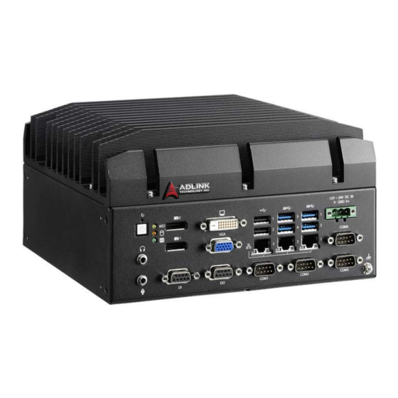
MVP-5000 Introduction 1.1 Overview ADLINK’s MVP-5000 series of value line fanless embedded com- ® ™ puting platforms, incorporating the 6th Generation Intel Core processor, provides single-side access for I/O ports, optimizing easy maintenance in industrial automation environments. The series retains the robust design of all ADLINK MXC/MXE lines, at a new extremely cost-effective price point. -
Page 16: Specifications
Fanless operation from 0°C to 50°C (w/ industrial SSD) This option guarantees cold boot of the system at 0°c and operation with 100% loading at 50° without sacrific- ing CPU frequency. The industrial solid-state drive stor- NOTE: NOTE: age option is required. 1.3 Specifications MVP-5001 MVP-5002... - Page 17 MVP-5000 MVP-5001 MVP-5002 MVP-5003 Built-in wide-range 12 to 24V DC input DC Input 3P pluggable connectors with latch (GND, V-, V+) AC Input Optional 160 W external AC-DC adapter for AC input Storage Internal SATA-III port for 2.5" HDD/SSD installation SATA High speed SATA 6 Gb/s support CFast...
-
Page 18: Figure 1-1: Mvp-5000 Functional Block Diagram
Under Windows 10 IoT Enterprise desktop with no application programs executed **Under Windows 10 IoT Enterprise with 100% CPU utilization ***Under conditions in which excessive environmental vibration may occur, it is recommended that an optional bracket be installed to secure USB and cable connectivity DDR4 Channel A DDR4 260 pin SODIMM... -
Page 19: Schematics And Dimensions
MVP-5000 1.4 Schematics and Dimensions All dimensions shown are in mm (millimeters). NOTE: NOTE: 131.5 Figure 1-2: Front View Introduction... -
Page 20: Figure 1-3: Left Side View
Figure 1-3: Left Side View Introduction... -
Page 21: Figure 1-4: Top View
MVP-5000 Figure 1-4: Top View Figure 1-5: Rear View Introduction... -
Page 22: Figure 1-6: Underside View
Figure 1-6: Underside View Introduction... -
Page 23: Front Panel I/O Connectors
MVP-5000 1.5 Front Panel I/O Connectors Figure 1-7: Front Panel I/O connectors and controls on the MVP-5000 front panel, as labeled, are as follows Power Button LED Indicators Audio (Mic, Phones) Reset Button DisplayPort x2 Digital Input ... -
Page 24: Power Button
1.5.1 Power Button The power button is a non-latched push button with a blue LED indicator. System is turned on when the button is depressed, and the power LED lights. If the system hangs, depress the button for 5 seconds to turn off the system completely. 1.5.2 LED Indicators In addition to the LED of the power button, three LEDs on the front... -
Page 25: Display Options
MVP-5000 Signal Pin Signal CN_DDPx0+ 11 CN_DDPx3- CN_DDPx0- CN_DDPx_AUX_SEL CN_DDPx1+ 14 CN_DDPx_CONFIG2 CN_DDPx_AUX+ CN_DDPx1- CN_DDPx2+ 17 CN_DDPx_AUX- CN_DDPx_HPD CN_DDPx2- CN_DDPx3+ 20 +V3.3_DDPx_PWR_CN Table 1-2: DisplayPort Pin Assignments Description 30-01119-0010 Active DisplayPort to HDMI adapter cable 30-01120-0010 Active DisplayPort to DVI adapter cable 30-01121-0010 Active DisplayPort to VGA adapter cable Table 1-3: Applicable Cable Types Display Options... -
Page 26: Digital I/O Connector
Display Option 1 Display Option 2 DisplayPort2 DVI-D 4096x2304@60Hz 1920X1080@60Hz DisplayPort2 4096x2304@60Hz 1920x1080@60Hz DVI-D 1920X1080@60Hz 1920x1080@60Hz Table 1-4: Maximum Available Resolutions with 2-Display Configuration 1.5.5 Digital I/O Connector The MVP-5000 provides 8 channels of non-isolation digital input and 8 channels of non-isolation digital output circuits, with spec and circuits as follows. -
Page 27: Table 1-5: Digital Input Connector Pin Legend
MVP-5000 Figure 1-9: Digital I/O Connector Pin Assignment Signal DI_GND Table 1-5: Digital Input Connector Pin Legend Signal Introduction... -
Page 28: Table 1-6: Digital Output Connector Pin Legend
Signal DO_GND Table 1-6: Digital Output Connector Pin Legend Figure 1-10: Digital Input Circuit Figure 1-11: Digital Output Circuit Introduction... -
Page 29: Dvi-D Connector
MVP-5000 1.5.6 DVI-D Connector The MVP-5000 provides one DVI-D connector for connection to an external monitor. Figure 1-12: DVI-D Connector Pin Assignment Pin Signal Pin Signal Pin Signal DVIdata 2- DVIdata 1- DVIdata 0- DVIdata 2+ DVIdata 1+ DVIdata 0+ DVIDC clock DVIDC data DVI clock +... -
Page 30: Usb 2.0 Ports
Signal G_VGA_R G_VGA_G G_VGA_B CRT_DDAT_CN G_VGA_HSYNC G_VGA_VSYNC CRT_DCLK_CN Table 1-8: VGA Connector Pin Legend 1.5.8 USB 2.0 Ports The MVP-5000 provides two USB 2.0 ports supporting Type A USB connection on the front panel. All USB ports are compatible with high-speed, full-speed and low-speed USB devices. The MVP-5000 supports multiple boot devices, including USB flash drive, USB external hard drive, USB floppy, USB CD-ROM and others. -
Page 31: Table 1-9: Active/Link Led Indicators
MVP-5000 IEEE 1588/802.1AS precision time synchronization IEEE 802.3Qav traffic shaper Interrupt moderation, VLAN support, IP checksum offload RSS and MSI-X to lower CPU utilization in multi-core sys- tems ECC - error correcting memory in packet buffers ... -
Page 32: Usb 3.0 Ports
1.5.10 USB 3.0 Ports The MVP-5000 provides four USB 3.0 ports supporting Type A USB3.0 connection on the front panel. All USB3.0 ports are com- patible with super-speed, high-speed, full-speed and low-speed USB devices. 1.5.11 DC Power Connector The DC power supply connector of the MVP-5000 is on the front panel. -
Page 33: Com Port Connectors
MVP-5000 1.5.12 COM Port Connectors The MVP-5000 provides four COM ports through D-sub 9 pin con- nectors. The COM1 & COM2 ports support RS-232/422/485 modes by BIOS setting, while COM3 and COM4 support only RS- 232. Figure 1-16: COM Port Signal Name RS-232 RS-422... -
Page 34: Figure 1-17: Cfast Host Connector (On Rear Panel)
I/O space, and an AHCI operating mode using memory space. The CFast card can function as a storage device for system instal- lation. Figure 1-17: CFast Host Connector (on rear panel) Introduction... -
Page 35: Internal I/O Connectors
MVP-5000 1.7 Internal I/O Connectors C D E Figure 1-18: Mainboard I/O Connectors 5V GPS module power header 3.3V GPS module power header USB2.0 connector Mini PCIe socket SATA connector 9V fan connector Jumpers: Clear CMOS (upper) N/C (lower) ... -
Page 36: Gps Module Power Header
Figure 1-19: CFast Board Connectors CFast socket 12V fan (optional) PCIe slot (connects to mainboard) Table 1-14: CFast Board Connector Legend 1.7.1 5V GPS Module Power Header 5V power supply via cable for mini PCIE GPS module cards. Introduction... -
Page 37: Gps Module Power Headers
MVP-5000 +V5_GPS 1.7.2 3.3V GPS Module Power Headers 3.3V power supply via cable for mini PCIE GPS module cards. +V3.3_GPS 1.7.3 USB 2.0 Connector One onboard USB 2.0 Type-A connector is provided for the inter- nal USB dongle, with only the upper port functional. 1.7.4 Mini PCIe Socket The internal Mini PCIe socket (Rev. -
Page 38: Fan Connector
1.7.6 9V Fan Connector DC 9V fan module power supply is provided through the connec- tor, to which the optional fan module connects when installed in the chassis. Signal FAN_GND P_+9V0_FAN1 FAN_TACH_CN FAN_PWM_CN 1.7.7 Clear CMOS Jumper Upon encountering an abnormal condition preventing the MVP- 5000 from booting, the jumper can clear the BIOS content stored in CMOS and restore default settings. -
Page 39: Extended Pwr/Reset Header
MVP-5000 1.7.8 Extended PWR/RESET header An internal header is provided for the Power and Reset buttons, with pin assignment as shown. Signal PWR_BTN-L RESET_BTN-L 1.7.9 USIM Slot The USIM slot connects to the Mini PCIe slot. Introduction... - Page 40 This page intentionally left blank. Introduction...
-
Page 41: Getting Started
MVP-5000 Getting Started 2.1 Unpacking Checklist Before unpacking, check the shipping carton for any damage. If the shipping carton and/or contents are damaged, inform your dealer immediately. Retain the shipping carton and packing materials for inspection. Obtain authorization from your dealer before returning any product to ADLINK. - Page 42 Getting Started...
- Page 43 MVP-5000 2. Remove the bottom cover by lifting. 3. Use 4 of the included M3 screws to fix a 2.5" HDD or SSD unit to the bracket from the accessory pack.. Getting Started...
- Page 44 4. Gently seat the drive into the SATA connector on the PCB. 5. Use 4 of the included M3 screws to mount the drive.. 6. Replace the bottom cover and refasten screws. Getting Started...
-
Page 45: Installing Cfast Cards
MVP-5000 2.3 Installing CFast Cards 1. Remove the screws fixing the CFast socket cover on the rear panel and remove the cover. 2. True the CFast card with the alignment guide. Getting Started... - Page 46 3. Gently insert the CFast card until it is firmly seated in the socket. Getting Started...
-
Page 47: Wall-Mounting The Mvp-5000
MVP-5000 4. Replace the socket cover and screws. 2.4 Wall-mounting the MVP-5000 All dimensions shown are in mm (millimeters). NOTE: NOTE: Due to the presence of ventilation holes, for safety, the device should ONLY be wall-mounted with the front and rear panels on the sides, NEVER on the top or underside. - Page 48 2. Use the 6 M4 screws shipped with the controller to fix the 2 wall-mount brackets, also included, to the chassis, according to the spacing dimensions of the screw holes and brackets, as shown. Getting Started...
-
Page 49: Driver Installation
MVP-5000 (R2.6) 3. Once final assembly as shown is complete, mount the MVP-5000 on the wall via screw holes. 2.5 Driver Installation Download requisite drivers, as follows, for your system from http:// www.adlinktech.com and install. The following drivers must be installed: Chipset driver ... -
Page 50: Adapter
2.6 Adapter The MVP-5000 with verified adapter meets the following specifica- tions. 12-24VDC/12.5-6.25A or 24VDC/6.25A Output Rating min. 2000m max. Operating Elevation Operating 0-50°C (32-122°F) Temperature Listed certified Getting Started... -
Page 51: A Appendix: Power Consumption
MVP-5000 Appendix A Power Consumption Information in this Appendix is for power budget planning and design purposes only. Actual power consumption may differ based on final application. NOTE: NOTE: A.1 Power Consumption Reference Power consumption as follows is based on lab data in which 24V DC is applied and current is measured by the DC power supply. - Page 52 This page intentionally left blank. Power Consumption...
-
Page 53: B Appendix: Bios Setup
MVP-5000 Appendix B BIOS Setup The Basic Input/Output System (BIOS) is a program that provides a basic level of communication between the processor and peripherals. In addition, the BIOS also contains codes for various advanced features applied to the MVP-5000. The BIOS setup program includes menus for configuring settings and enabling features of the MVP-5000. -
Page 54: Bios Information
BIOS Information Shows current system BIOS Vendor, Core Version, BIOS Version, Board Version and Product Name. Platform Information Shows current system Platform Name, CPU Stepping, PCH SKU, PCH Stepping and GT information. FW Information Shows current system Memory RC version, Microcode Path, IGFX VBIOS version and ME FW version. -
Page 55: System Time/System Date
MVP-5000 System Time/System Date Allows adjustment of system time and date, as follows. 1. Highlight System Time or System Date using the up and down <Arrow> keys 2. Enter new values using the keyboard and select <Enter> 3. Select < Tab > to move between fields. The date must be entered in MM/DD/YY format, ... -
Page 56: Cpu Configuration
B.2.1CPU Configuration BIOS Setup... -
Page 57: Hyper-Threading
MVP-5000 Hyper-Threading Enabled for Windows 7, 10 IoT Enterprise, and Linux (optimized for Hyper-Threading Technology). When Disabled only one thread per enabled core is enabled. Active Processor Cores Number of cores to enable in each processor package. Intel Virtualization Technology When enabled, a VMM can utilize the additional hardware capabil- ities provided by Vanderpool Technology. -
Page 58: Memory Configuration
B.2.2 Memory Configuration Shows current system Memory RC Version and values for mem- ory frequency, total memory, DIMM#0, and DIMM#1. BIOS Setup... -
Page 59: System Agent (Sa) Configuration
MVP-5000 B.2.3 System Agent (SA) Configuration VT-d Enables/disables VT-d capability. BIOS Setup... -
Page 60: Graphics Configuration
B.2.4 Graphics Configuration GTT Size Sets GTT size. Aperture Size Sets aperture size, with MMIO BIOS assignment exceeding 4GB automatically enabled when 2048MB aperture is selected, avail- able when CSM Support is disabled. DVMT Pre-Allocated Sets size of DVMT 5.0 pre-allocated (fixed) graphics memory used by the internal graphics device. -
Page 61: Onboard Device Configuration
MVP-5000 B.2.5 Onboard Device Configuration Serial Port 1 to 4 Configuration Sets port type (RS-232/422/485) for Serial Ports 1 and 2 only. LAN #1 (Intel I211AT) Enables/Disables onboard Intel I211AT LAN controller. LAN #1(I211AT) Launch PXE OpROM Enables or disables execution of LAN boot-rom to add boot option for legacy network devices. -
Page 62: Lan #2(I211At) Launch Pxe Oprom
LAN #2(I211AT) Launch PXE OpROM Enables or disables execution of LAN boot-rom to add boot option for legacy network devices. LAN #3 (Intel I211AT) Enables/Disables onboard Intel I211AT LAN controller. LAN #3(I211AT) Launch PXE OpROM Enables or disables execution of LAN boot-rom to add boot option for legacy network devices. -
Page 63: Advanced Power Management
MVP-5000 Console Redirection Settings Sets miscellaneous parameters for COM Ports 1 to 4 and EMS COM. B.2.6 Advanced Power Management State After G3 Determines the state the computer enters when power is restored after power loss, from among Last State, Power On, and Power Option Description Retains system power off after power is... -
Page 64: State After G3
State After G3 Sets the state entered when power is re-applied after a power fail- ure (G3 state). RTC Wake system from S5 Enable or disable system wake on alarm event, with FixedTime waking the system at the hr/min/sec specified, and DynamicTime waking the system at the current time + Increase minute(s). -
Page 65: Xhci Hand-Off
MVP-5000 XHCI Hand-off A workaround for OS without XHCI hand-off support, where XHCI ownership change should be claimed by the XHCI driver. USB Mass Storage Driver Support Enable/Disable USB mass storage driver support. Port 60/64 Emulation Enables I/O port 60h/64h emulation support, should be enabled for complete USB keyboard legacy support for OS not recognizing USB ports. -
Page 66: Sata Configuration
B.2.8 SATA Configuration SATA Port and CFast Card Enable or Disable SATA Port and CFast Card. for Hub port the delay is taken from the Hub descriptor. BIOS Setup... -
Page 67: Csm Configuration
MVP-5000 B.2.9 CSM Configuration CSM Support Enable or Disable CSM Support. GateA20 Active UPON REQUEST disables GA20 using BIOS services, and ALWAYS prevents GA20 from being disabled, useful when any RT code exceeding 1MB is executed. Option ROM Messages Sets display mode for Option ROM. Boot option filter Controls Legacy/UEFI ROM priority. -
Page 68: Network
Network Controls execution of UEFI and Legacy PXE OpROM. Storage Controls execution of UEFI and Legacy Storage OpROM. Video Controls execution of UEFI and Legacy Video OpROM. Other PCI devices Determines OpROM execution policy for devices other than Net- work, Storage, and Video. B.2.10 Network Stack Configuration Enables/disables UEFI Ipv4/Ipv6 network stack function. -
Page 69: Pc Health Status
MVP-5000 B.2.11 PC Health Status (Opens from Advanced/NCT6106D HW Monitor) Hardware monitor based on Super I/O shows Board Temperature, CPU Temperature, Fan Speed, Fan Control Mode, and Voltage values. BIOS Setup... -
Page 70: Security
B.3 Security If only the Administrator password is set, access s limited and the password requested on Setup. If User password is set, it acts as a power-on password and must be entered to boot or enter setup. In Setup the user receives Administrator Password Sets Administrator Password. -
Page 71: Bios Lock
MVP-5000 BIOS Lock Enable/Disable the PCH BIOS Lock (BLE bit). B.4 Boot Setup Prompt Timeout Number of seconds before setup activation key is launched, with 65535(0xFFFF) setting indefinite waiting. Bootup Num-Lock State Sets keypad Number Lock status following boot. BIOS Setup... -
Page 72: Quiet Boot
Quiet Boot Option Description Disabled Directs BIOS to display POST messages Enabled Directs BIOS to display the OEM logo. Fast Boot Option Description Disabled Directs BIOS to perform all POST tests. Directs BIOS to skip certain POST tests to boot Enabled faster. - Page 73 MVP-5000 Hard Drive BBS Priorities Specifies the priority of boot devices. All installed boot devices are detected during POST and displayed. Target Boot Option # and click to select the desired device. BIOS Setup...
-
Page 74: Save & Exit
B.5 Save & Exit Discard Changes and Exit Discards all changes and exits BIOS setup Save Changes and Reset Saves all changes and reboots the system, with new settings tak- ing effect Discard Changes Resets system setup without saving any changes Restore Defaults Sets all BIOS options to default settings, designed for maximum system stability but less than maximum performance. -
Page 75: Save As User Defaults
MVP-5000 Restore Defaults if the computer encounters system configuration problems. Save as User Defaults Saves all changes to this point as user defaults Restore User Defaults Restores user defaults to all setup options Launch EFI Shell from filesystem device Attempts to launch EFI Shell application (Shell.efi) from one of the available filesystem devices BIOS Setup... - Page 76 This page intentionally left blank. BIOS Setup...
-
Page 77: C Appendix: Watchdog Timer (Wdt)
MVP-5000 Appendix C Watchdog Timer (WDT) Function Library This appendix describes use of the watchdog timer (WDT) func- tion library for the MVP-5000 controller. The watchdog timer is a hardware mechanism provided to reset the system if the operating system or an application stalls. After starting, the watchdog timer in the application must be periodically reset before the timer expires. - Page 78 C/C++ int __stdcall AwlWatchdogSetTrigger(int Time, int isEnbaled) Parameters Time The period (in seconds) before WDT is triggered. isEnabled Directs WDT whether to start run timer, where 0 stops run- ning or doesn't run, 1 starts running timer. Return codes 0: Operation successful -1: Operation failed AwlWatchdogSetTrigger_ex Sets/disables WDT allows counter unit to be set to seconds or...
-
Page 79: D Appendix: Digital Input/Output
Matrix DI/O API library files and a demo program (incl. source code) can be downloaded from http://www.adlinktech.com. To use the DI/O function library for MVP-5000 series, include the header file matrix_dio.h and linkage library matrix_dio.lib (matrix_diox64.lib for x64 OS) in the C++ project. DI/O func- tions are as follows. - Page 80 Indexes MVP-5000 digital input channels 1 to 8 (corresponding value 0 to 7) Index of MVP-5000 digital input channels 9 to 16 (correspond- ing value 8 to 15). Return codes Corresponding input/output line is HIGH Corresponding input/output line is LOw AwlDioGetInfo Reads the info string of a digital input/output line.
- Page 81 MVP-5000 Return codes 0: Operation Success -1: Operation Failed Digital Input/Output Function Library...
- Page 82 This page intentionally left blank. Digital Input/Output Function Library...
-
Page 83: Important Safety Instructions
MVP-5000 Important Safety Instructions For user safety, please read and follow all instructions, Warnings, Cautions, and Notes marked in this manual and on the associated device before handling/operating the device, to avoid injury or damage. S'il vous plaît prêter attention stricte à tous les avertissements et mises en garde figurant sur l'appareil , pour éviter des blessures ou des dommages. - Page 84 Never attempt to repair the device, which should only be serviced by qualified technical personnel using suitable tools A Lithium-type battery may be provided for uninterrupted backup or emergency power. Risk of explosion if battery is replaced with one of an incorrect type;...
- Page 85 MVP-5000 BURN HAZARD Touching this surface could result in bodily injury. To reduce risk, allow the surface to cool before touching. RISQUE DE BRÛLURES Ne touchez pas cette surface, cela pourrait entraîner des blessures. Pour éviter tout danger, laissez la surface refroidir avant de la toucher.
- Page 86 This page intentionally left blank. Important Safety Instructions...
-
Page 87: Getting Service
San Jose, CA 95138, USA Tel: +1-408-360-0200 Toll Free: +1-800-966-5200 (USA only) Fax: +1-408-360-0222 Email: info@adlinktech.com ADLINK Technology (China) Co., Ltd. Address: (201203) 300 Fang Chun Rd., Zhangjiang Hi-Tech Park Pudong New Area, Shanghai, 201203 China Tel: +86-21-5132-8988 Fax: +86-21-5132-3588 Email: market@adlinktech.com... - Page 88 84 Genting Lane #07-02A, Cityneon Design Centre Singapore 349584 Tel: +65-6844-2261 Fax: +65-6844-2263 Email: singapore@adlinktech.com ADLINK Technology Singapore Pte. Ltd. (Indian Liaison Office) Address: #50-56, First Floor, Spearhead Towers Margosa Main Road (between 16th/17th Cross) Malleswaram, Bangalore - 560 055, India Tel: +91-80-65605817, +91-80-42246107 Fax:...
Need help?
Do you have a question about the MVP-5000 Series and is the answer not in the manual?
Questions and answers