Danish Interpretation Systems DCS 6000 User Manual
Digital conference system digital infrared wireless audio distribution system
Hide thumbs
Also See for DCS 6000:
- User manual (66 pages) ,
- User manual (42 pages) ,
- User manual (19 pages)

Related Manuals for Danish Interpretation Systems DCS 6000


Summary of Contents for Danish Interpretation Systems DCS 6000
- Page 1 DCS 6000 User Manual Digital Conference System DCS 6000 Digital Infrared Wireless Audio Distribution System...
- Page 2 User Manual User Manual DCS 6000 Digital IR System rev H.docx Copyright © 2009-2012 DIS 15-11-2012 No part of this publication may be reproduced or utilised in any form or by any means without permission in writing from the publisher.
-
Page 3: Table Of Contents
Planning radiators ......15 4.5.2 Main menu ..........31 User Manual DCS 6000 Digital IR System rev H.docx Copyright © 2009-2012 DIS 15-11-2012 No part of this publication may be reproduced or utilised in any form or by any means without permission in writing from the... - Page 4 Guaranteed footprints ....... 59 Operation ..........46 Reception test mode ......46 User Manual DCS 6000 Digital IR System rev H.docx Copyright © 2009-2012 DIS 15-11-2012 No part of this publication may be reproduced or utilised in any form or by any means without permission in writing from the...
-
Page 5: Important
If there is any sign of leakage or corrosion, replace the battery The individual units in the DCS 6000 system are pack. Ensure that only the battery pack BP 6001 Warranty minimum covered by 12 months warranty is used. -
Page 6: System Description And Planning
The DCS 6000 Digital IR system can also be used for music distribution (mono as well as stereo). Three multi-channel infra-red receivers are 3.1.3... -
Page 7: Signal Processing
For music the HI-FI quality mode gives information that can be distributed on each near CD quality. carrier. The compression factor is also related to the required audio quality. User Manual DCS 6000 Digital IR System rev H.docx... -
Page 8: Carriers And Channels
User Manual Figure 3.2-B Overview of the signal processing (for one carrier) The DCS 6000 Digital IR system can transmit up 3.2.4 Carriers and channels to 8 different carrier signals (depending on the transmitter type). Each carrier can contain up to 4 different audio channels. -
Page 9: Aspects Of Ir Distribution Systems
As on the coverage area can be seen in Figure 3.3-A shown, the size and position of the footprint and Figure 3.3-B. The radiation pattern is the User Manual DCS 6000 Digital IR System rev H.docx... -
Page 10: Ambient Lighting
Dark or rough surfaces absorb large proportions of the infra-red signal (see Figure 3.3-F). With few exceptions it cannot pass through materials that are opaque to visible light. User Manual DCS 6000 Digital IR System rev H.docx... -
Page 11: Positioning The Radiators
(see Figure 3.3-G and Figure 3.3-H). Figure 3.3-I Combination of direct and reflected radiation Figure 3.3-G Infra-red signal blocked by a person in front of the participant User Manual DCS 6000 Digital IR System rev H.docx... - Page 12 ‘shaded’ area with an additional radiator (see Figure 3.3-M). The figures below illustrate the positioning of the radiators: Figure 3.3-L Radiator positioning in a conference hall with auditorium seating and podium User Manual DCS 6000 Digital IR System rev H.docx...
-
Page 13: Overlapping Footprints And
The lower the carrier frequency, the less susceptible the receiver is differences in signal delays. The signal delays can be compensated by using the delay compensation switches on the radiators (see section 3.5). User Manual DCS 6000 Digital IR System rev H.docx... -
Page 14: Planning An Dcs 6000 Digital Infra-Rectangular Footprints
1.4 approximately (see Figure 3.4-C). Figure 3.4-A A typical rectangular footprint for a mounting angle of 15° The effect of overlapping footprints Figure 3.4-C User Manual DCS 6000 Digital IR System rev H.docx... -
Page 15: Planning Radiators
Figure 3.4-E Asymmetrical arrangement of radiator cabling (to be avoided) DIS_FCPv5.3_.xlt eases the work planning radiator coverage. The Program is to be found at the ‘DCS 6000 Digital IR System User Manual CD’ Signal delay differences can occur due to 3.4.3... -
Page 16: Setting Radiator Delay Switches
8. Set the delay switches to the calculated In these cases set the delay switches on all switch positions. radiators to zero and determine whether to compensate for radiation signal delay (see section 3.5.3). User Manual DCS 6000 Digital IR System rev H.docx... - Page 17 4. Reconnect the cable to the radiator and repeat steps 2 to 4 for the other radiators User Manual DCS 6000 Digital IR System rev H.docx...
-
Page 18: System With Two Or More
delay switch positions in a master-slave 4. Add the master-to-slave signal delay to each configuration: radiator connected to the slave transmitter. 5. Determine the maximum signal delay. User Manual DCS 6000 Digital IR System rev H.docx... - Page 19 593-481 = 112 112/33 = 3.39 = 3 Slave 313+280 = 593 593-593 = 0 0/33 = 0 Table 3.5-4 Calculation of the delay switch positions of a system with two transmitters User Manual DCS 6000 Digital IR System rev H.docx...
-
Page 20: System With More Than 4 Carriers
2. Set the transmitter in the Test-mode (see blocking obstacle or add an extra radiator to section 4.5.7). For each channel, a different cover the shaded area. test tone frequency will be transmitted. User Manual DCS 6000 Digital IR System rev H.docx... -
Page 21: Black Spots
Black spots can occur in case a transmitter is (see section 4.5.11) and re-check the reception. located in the same room as the radiators. In that case, disable the mini IR radiator of the User Manual DCS 6000 Digital IR System rev H.docx... -
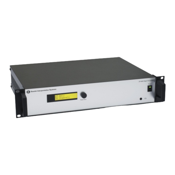
Page 22: Dt 6008 & Dt 6032 Transmitters
6000 Digital IR system. It accepts asymmetrical audio sources from a maximum of 32 external channels (dependent on the transmitter type) and can be used with the DCS 6000 Digital Note: The mini IR-radiator and the headphone output Conference System. It can also be used with... -
Page 23: Installation
60xx range transmitter: Connecting the DCS 6000 Conference System Connecting other external audio sources Connecting an emergency signal switch Connecting another transmitter User Manual DCS 6000 Digital IR System rev H.docx... -
Page 24: Connecting An Emergency Signal
If the auxiliary input is 'Stereo' or 'Stereo to Mono', the audio signals on the Aux-Left and Aux-Right inputs are distributed to all output channels, overriding all other audio inputs. Figure 4.3-D Connecting another transmitter User Manual DCS 6000 Digital IR System rev H.docx... -
Page 25: Using The Configuration Menu
4.5. Figure 4.4-A gives an overview of the menu structure. A general description of how to use Figure 4.4-A Menu overview User Manual DCS 6000 Digital IR System rev H.docx... -
Page 26: Navigate Through The Menu
(when available) and configuration options. The value of an option can repeat steps 3 to 5. be changed by selecting a value from a list of available values. User Manual DCS 6000 Digital IR System rev H.docx... -
Page 27: Examples
Each example starts at the reached the first item (A) of the sub-menu. Transmitter Status screen. Example: 3 Enquiry 4 Setup 4 C Nr. of Ch. 4 A Transmission 32 Channels User Manual DCS 6000 Digital IR System rev H.docx... - Page 28 4 Setup ... Push to confirm 4G Carrier 2 Enabled 7 Turn to move the < Back ... cursor Ready to the second line. 4G Carrier 2 Enabled Transmitter 32 Channels User Manual DCS 6000 Digital IR System rev H.docx...
- Page 29 9 Turn clockwise until channel name < Back ... changes to: • - - - 4F Channel 12 Ready Spanish Push to confirm. Transmitter 4F Channel 12 32 Channels • - - - User Manual DCS 6000 Digital IR System rev H.docx...
- Page 30 Push to confirm 4D Channel 11 Turn to move the < Back ... Mono SQ In 00 cursor to the quality Ready option. 4D Channel 11 Transmitter Mono SQ In 10 32 Channels User Manual DCS 6000 Digital IR System rev H.docx...
-
Page 31: Configuration And Operation
4 Setup . . . Go to the ‘Setup’ sub-menu (see sections 4.5.7 and higher) Note: To enter the Setup sub-menu, push and hold the button for at least 3 seconds User Manual DCS 6000 Digital IR System rev H.docx... -
Page 32: View Fault Status
Radiator Fault No Radiators No Network Network Error Push the menu button to remove the fault message from the screen and to go back to the User Manual DCS 6000 Digital IR System rev H.docx... -
Page 33: Set Monitoring Options
The monitoring headphone output is transmitter firmware. switched off during normal operation, but is active when the sensitivity of one of the inputs is being changed. Volume: “dd” dB {-31 ... 0} User Manual DCS 6000 Digital IR System rev H.docx... -
Page 34: Set Transmission Mode
Set number of channels that will be used can be set. Note that the maximum number of channels depends on the transmitter type (8 or 32 channels) and the chosen quality modes. User Manual DCS 6000 Digital IR System rev H.docx... -
Page 35: Set Channel Quality And Assign
Select this option to go to the ‘Per Channel Settings’ menu. Note: An asterisk (*) is shown behind the channel number when the channel in the configured quality does not fit on the available carriers (see section 3.2.4). User Manual DCS 6000 Digital IR System rev H.docx... -
Page 36: Set Channel Names
Normally channels automatically 4.5.11 Disable or enable carriers assigned to the available carriers. However, when the reception quality of a specific carrier is not good, that carrier can be disabled manually. User Manual DCS 6000 Digital IR System rev H.docx... -
Page 37: View Carrier Assignments
When the option ‘Stereo’ is chosen, the signals on both Aux. inputs are distributed as a stereo signal to all channels. This setting can for instance be used to transmit a music signal during breaks in a conference. User Manual DCS 6000 Digital IR System rev H.docx... -
Page 38: Set Sensitivity Of The Inputs
Set the sensitivity of all audio inputs to a user defined level. Level “xx” dB: {-6 ... +6} Per Input ... Select this option to go to the ‘Per Input Sensitivity Settings’ menu. User Manual DCS 6000 Digital IR System rev H.docx... -
Page 39: Enable / Disable Ir-Monitoring
The transmitter can be assigned a user-defined 4.5.17 Choose transmitter name name. This name is used in the Transmitter User Manual DCS 6000 Digital IR System rev H.docx... -
Page 40: Digital Radiators
1. Mains input - Male Euro mains connector. Figure 5.1-B RA 6013 and RA 6025 front view The radiators have automatic mains voltage selection. 2. IR signal input/loop-through - Two HF BNC connectors for connecting the radiator User Manual DCS 6000 Digital IR System rev H.docx... -
Page 41: Radiator Status Indication
Radiators in permanent installations can be 5.1.3 Mounting the radiators either fixed to a wall, hung under a ceiling or balcony or secured to any sturdy material, using User Manual DCS 6000 Digital IR System rev H.docx... - Page 42 Attaching the plate to the suspension bracket Figure 5.1-E Attaching the stud of a floor stand to the Figure 5.1-D Attaching the suspension bracket to the radiator suspension bracket of the radiator User Manual DCS 6000 Digital IR System rev H.docx...
- Page 43 200 kg The bolts and plugs delivered with the WB 6000 (440 lb). wall bracket are only intended for mounting the unit on a solid brick or concrete wall. User Manual DCS 6000 Digital IR System rev H.docx...
-
Page 44: Connecting Radiators To The
When connecting infra-red radiators, do not split the cable, else the system will not function correctly. Figure 5.1-I Attaching the radiator to the wall mounting bracket User Manual DCS 6000 Digital IR System rev H.docx... -
Page 45: Digital Receivers
This ensures that the receiver is totally 2. Headphone connector - A 3.5 mm (0.14 switched-of and no energy is consumed from the inch) stereo jack output socket for the batteries or the battery pack. User Manual DCS 6000 Digital IR System rev H.docx... -
Page 46: Operation
The infra-red receivers can operate with The test mode is deactivated when the receiver disposable batteries (2x AA-size alkaline cells) is switched off. or with a rechargeable battery pack (not available yet). User Manual DCS 6000 Digital IR System rev H.docx... -
Page 47: Receiver Headphones
6021 Stereo headphones (recommended) The headphones connect with the receivers via a Receiver headphones Any other compatible type 3.5 mm (0.14 inch) stereo jack connector. Suitable headphone types are: User Manual DCS 6000 Digital IR System rev H.docx... -
Page 48: Ct 6056 Charging Tray
3. Receiver positions - One charging unit can 2. Mains on/off switch the receiver or battery pack. Receivers can therefore charge up to 56 receivers simultaneously safely be left in their charging positions when they are not used. User Manual DCS 6000 Digital IR System rev H.docx... - Page 49 If there is any sign of leakage or corrosion, replace the battery pack. Ensure that only the battery pack BP 6001 is used. The battery pack has to be replaced at least every five years User Manual DCS 6000 Digital IR System rev H.docx...
-
Page 50: Troubleshooting
Switch the receiver on and check whether the display indicates a channel. Ensure that the receiver picks up sufficient IR signal and check whether the antenna symbol becomes visible. User Manual DCS 6000 Digital IR System rev H.docx... - Page 51 Receiver discharges very quickly: Replace the battery pack and check whether the problem is resolved. Bad coverage: Do the tests as described in section 3.6. User Manual DCS 6000 Digital IR System rev H.docx...
-
Page 52: Typical Schematics
User Manual 9 Typical schematics The following schematic is showing a typical application with various units in the DCS 6000 system: User Manual DCS 6000 Digital IR System rev H.docx... -
Page 53: 10 Technical Specifications
Maximum number of radiators ............notice. 30 per HF output Maximum cable length 900 m (2,970 feet) per HF output. Working condition ....Fixed, stationary or System Environmental Conditions transportable Temperature range User Manual DCS 6000 Digital IR System rev H.docx... -
Page 54: Digital Transmitter
Mains voltage ..100 to 240 V, 50 to 60 Hz Power consumption maximal ..........55 W Power consumption (standby) ......................29 W Specifications are subject to change without notice. User Manual DCS 6000 Digital IR System rev H.docx... -
Page 55: High Power Radiators
11 Wrms 22 Wpp (RA 6013), 21 Wrms 42 Wpp (RA 6025) Total optical peak intensity 12 W/sr (RA 6013), 24 W/sr (RA 6025) Angle of half intensity ..........+/- 22° User Manual DCS 6000 Digital IR System rev H.docx... -
Page 56: Digital Ir Receivers
........ 50 g (0.11 lb) Voltage ..........2.4 V Electrical characteristics Capacity ........1100 mAh Specified lifetime: ..Minimum 2 years or 500 cycles (under normal conditions) Specifications are subject to change without notice. User Manual DCS 6000 Digital IR System rev H.docx... -
Page 57: Mains Cables
Specifications are subject to change without notice. Pin 1 Signal + Cinch (RCA phone) connector (male) Pin 2 Signal – 3.5 mm Jack plug 10.6.3 Earphones Tip (1) Signal left Ring (2) Signal Right User Manual DCS 6000 Digital IR System rev H.docx... -
Page 58: Accessories
DH 6021 Stereo headphones ........14 11 03055 Headphones Cable – XLR to RCA phone ........... 10 03 15001 Audio Cables Specifications are subject to change without notice Brackets & Stands User Manual DCS 6000 Digital IR System rev H.docx... -
Page 59: Guaranteed Footprints
[m2] 1643 11,5 1440 10,5 1026 -0,5 -6,5 1519 12,5 1189 -1,5 -10,5 1364 1140 -1,5 -10,5 -0,5 -5,5 -6,5 -1,5 -7,5 -10,5 -0,5 -4,5 -5,5 -7,5 -0,5 -0,5 -3,5 -4,5 User Manual DCS 6000 Digital IR System rev H.docx...
Need help?
Do you have a question about the DCS 6000 and is the answer not in the manual?
Questions and answers