Danish Interpretation Systems DCS 6000 User Manual
Digital infrared wireless language distribution system
Hide thumbs
Also See for DCS 6000:
- User manual (66 pages) ,
- User manual (64 pages) ,
- User manual (19 pages)
Table of Contents
Advertisement
Quick Links
See also:
User Manual
Advertisement
Table of Contents

Related Manuals for Danish Interpretation Systems DCS 6000


Summary of Contents for Danish Interpretation Systems DCS 6000
- Page 1 DCS 6000 User Manual Digital Conference System DCS 6000 Digital Infrared Wireless Language Distribution System Danish Interpretation Systems...
- Page 2 Danish Interpretation Systems User Manual Copyright © 2005 DIS DCS6000 DIGITAL IR SYSTEM REV B.DOC 03-05-2006 No part of this publication may be reproduced or utilised in any form or by any means without permission in writing from the publisher.
-
Page 3: Table Of Contents
Positioning the radiators ....... 11 4.4.3 Examples ..........26 3.3.6 Overlapping footprints and multipath Configuration and operation ....30 effects 4.5.1 Start-up ..........30 Planning an DCS 6000 Digital infra-red 4.5.2 Main menu..........30 radiation system ............13 3.4.1 Rectangular footprints......13 4.5.3 View transmitter status ......30 3.4.2 Planning radiators ......... - Page 4 Danish Interpretation Systems User Manual 4.5.7 Set transmission mode......33 Receiver headphones......... 45 4.5.8 Set number of channels ......33 Troubleshooting ..........46 4.5.9 Set channel quality and assign inputs to Typical schematics ..........48 channels 34 Technical Specifications ........49 4.5.10 Set channel names .........35...
-
Page 5: Important
To avoid moisture condensations do not install the unit The individual units in the DCS 6000 system are where the temperature may rise rapidly. minimum covered by 12 months warranty against defects in materials or workmanship. -
Page 6: System Description And Planning
3.1.3 Infra-red receivers it through headphones. The DCS 6000 Digital IR system can also be used for Three multi-channel infra-red receivers are available: music distribution (mono as well as stereo). -
Page 7: Signal Processing
Infra-red radiation spectrum in relation to other analogue audio channels . spectra 3.2.3 Quality modes 3.2.2 Signal Processing The DCS 6000 Digital IR system can transmit audio in The DCS 6000 Digital IR system uses high frequency four different quality modes: carrier signals... -
Page 8: Carriers And Channels
Danish Interpretation Systems User Manual 3.2.4 Carriers and channels The DCS 6000 Digital IR system can transmit up to 8 different carrier signals (depending on the transmitter type). Each carrier can contain up to 4 different audio channels. The maximum number of channels per carrier is dependent on the selected quality modes. -
Page 9: Aspects Of Infra-Red Distribution Systems
Danish Interpretation Systems User Manual 3.3 Aspects of infra-red distribution systems A good infra-red distribution system ensures that all delegates in a conference venue receive the distributed signals without disturbance. This is achieved by using enough radiators, placed at well planned positions, so that the conference venue is covered with uniform Irradiation of adequate strength. -
Page 10: Ambient Lighting
Danish Interpretation Systems User Manual 3.3.3 Ambient lighting The DCS 6000 Digital IR system is practically immune for the effect of ambient lighting. Fluorescent lamps (with or without electronic ballast or dimming facility), such as TL lamps or energy saving lamps give no problems with the DCS 6000 Digital IR system. -
Page 11: Positioning The Radiators
Danish Interpretation Systems User Manual Problems caused by shadows from walls or furniture can The figures below illustrate how infra-red radiation can be solved by ensuring that there are sufficient radiators be directed to conference participants. In Figure 3.3-I, and that they are well positioned, so that a strong enough... -
Page 12: Overlapping Footprints And Multipath
Danish Interpretation Systems User Manual always directed towards the radiators, you do not need radiators at the back (see Figure 3.3-L). If the path of the infra-red signals is partially blocked, e.g. under balconies, you should cover the ‘shaded’ area with an additional radiator (see Figure 3.3-M). -
Page 13: Planning An Dcs 6000 Digital Infra-Red Radiation System
The signal delays can be compensated by using the delay compensation switches on the radiators (see section 3.5). 3.4 Planning an DCS 6000 Digital infra- red radiation system 3.4.1 Rectangular footprints Determining the optimal number of infra-red radiators required to give 100% coverage of a hall can normally only be done by performing a site test. -
Page 14: Planning Radiators
Tip: The Footprint Calculation Program DIS_FCPv5.3_.xlt eases the work planning radiator coverage. The Program is to be found at the ‘DCS 6000 Digital IR System User Manual CD’ 3.4.3 Cabling Signal delay differences can occur due to differences in the cable length from the transmitter to each radiator. -
Page 15: Setting The Radiator Delay Switches
Tip: The Delay Switch Calculation tool DIS_DSCv5.3a_.XLT eases the calculation of the delay switch positions. The Program is to be found at the ‘DCS 6000 Digital IR System User Manual CD’ Manual 01 18 05675... - Page 16 Danish Interpretation Systems User Manual Note: The used cable signal delay per meter is an example. Use the actual signal delay per meter in this calculation as specified by the manufacturer. Caution: Turn the delay switches carefully to a new...
-
Page 17: System With Two Or More Transmitters In
Danish Interpretation Systems User Manual Figure 3.5-B and Table 3.5-2 illustrate the calculation of the signal delays and the delay switch positions. Note The calculated delay switch positions based on impulse response time can differ from the calculated 584 ns 350 ns delay switch positions based on cable lengths. - Page 18 Danish Interpretation Systems User Manual Note: When a master-slave configuration is used for rooms which are always separated, the delay switch positions can be determined per system and the delay caused by transmission from master to slave transmitter can be ignored.
-
Page 19: System With More Than 4 Carriers And A Radiator Under A Balcony
Danish Interpretation Systems User Manual 3.5.3 System with more than 4 carriers 3.6.2 Testing during a meeting and a radiator under a balcony Set a receiver in the Test-mode and select the highest available carrier. The quality of the received Figure 3.5-D illustrates a situation in which a radiation... -
Page 20: Interference From Ir Systems
Danish Interpretation Systems User Manual a surface with a high reflectabiliy can also cause problem and/or add an extra radiator. Note that due to the multipath problems. physical characteristics of the signal distribution, it is not always possible to completely avoid multi path effects. -
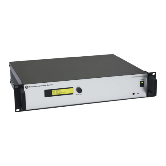
Page 21: Dt 6008 & Dt 6032 Transmitters
Digital IR system. It accepts asymmetrical audio sources from a maximum of 32 external channels (dependent on the transmitter type) and can be used with the DCS 6000 Digital Conference System. It can also be used with analogue discussion and interpretation systems (e.g. CIE 9000), or as a stand-alone system distributing external audio sources. -
Page 22: Installation
Connecting another transmitter 4.3.1 Connecting the DCS 6000 Conference System The transmitter is connected to DCS 6000 Conference System to an AO 6008 Audio Output Unit. Each AO 6080 can feed up to 8 ‘Audio Signal Inputs’ in the transmitter. -
Page 23: Connecting To Another Transmitter
Danish Interpretation Systems User Manual closed switch depends on the configuration of the 4.3.4 Connecting to another transmitter auxiliary inputs (see also section 0): If the auxiliary input is 'Mono + Emergency', the The transmitter can be operated in slave mode to loop audio signal on the Aux-Right input is distributed to through the IR radiator signals from a master transmitter. -
Page 24: Using The Configuration Menu
Danish Interpretation Systems User Manual 4.4 Using the configuration menu 4.4.1 Overview All configuration and operation options of the transmitter section 4.4.2. Some examples are given in section 4.4.3. are set via an interactive menu, using a 2x16 character The detailed descriptions of all menu items can be found LCD display and a ‘turn-and-push’... -
Page 25: Navigate Through The Menu
Danish Interpretation Systems User Manual To navigate through the Main menu: 4.4.2 Navigate through the menu Turn the button to move through the Main menu items. The item number and title starts blinking. (The first item, Operating the menu is always a sequence of alternating Transmitter Status, doesn’t blink.) -
Page 26: Examples
Danish Interpretation Systems User Manual To jump back from a sub-menu to an item of the To jump back from an item of the Main menu to the Main menu: Transmitter Status: Turn the button to move the cursor to the Main Turn the button to the <... - Page 27 Danish Interpretation Systems User Manual 4.4.3.1 Example 1: Disable carrier 2. (See also section 4.5.11). Turn button Turn to select Transmitter 4G Carrier 2 select the ‘Setup’ item ‘Disabled’. 32 Channels Enabled (4) in the Main menu. Push to confirm...
- Page 28 Danish Interpretation Systems User Manual 4.4.3.2 Example 2: Assign a user defined name to ch. 12. (See also section 0.) Turn button Push to confirm. Transmitter 4F Channel 12 select the ‘Setup’ item 32 Channels • - - - (4) in the Main menu.
- Page 29 Danish Interpretation Systems User Manual 4.4.3.3 Example 3: Set channel 11 to transmit a Stereo signal in Premium Quality, using audio inputs 14 (L) and 15 (R) as source. (See also section 4.5.9.) Turn button Turn to select the Transmitter 4D Channel 11 select the ‘Setup’...
-
Page 30: Configuration And Operation
Danish Interpretation Systems User Manual 4.5 Configuration and operation The next sections give descriptions of the possible 4.5.3 View transmitter status configuration options. Each description is followed by the relevant menu items with detailed information per The first screen of the Main menu gives information menu option. -
Page 31: View Fault Status
Danish Interpretation Systems User Manual 4.5.4 View fault status The fault status of the radiators can be seen in the second screen of the Main menu: 1 Fault Status 1 Fault Status No Faults Options Description No Faults The connected radiators function without problems. -
Page 32: Set Monitoring Options
Danish Interpretation Systems User Manual When the headphone output is disabled (see section 4.5.5 Set monitoring options 4.5.16), the output level can not be changed and the level indicator is not visible. The Monitoring sub-menu (2) is used to set which signal The ‘Source/volume’... -
Page 33: Set Transmission Mode
Danish Interpretation Systems User Manual 4.5.7 Set transmission mode 4.5.8 Set number of channels The Transmission Mode menu item (4A) is used to select Via sub-menu item 4B the number of channels that will which signals will be distributed over the channels. It is be used can be set. -
Page 34: Set Channel Quality And Assign Inputs To Channels
Danish Interpretation Systems User Manual 4.5.9.1 Per Channel Settings 4.5.9 Set channel quality and assign inputs to channels 4 Setup/4C Ch. Quality The audio quality of the channels (mono/stereo, 4C Channel 01 standard/premium) can be set in sub-menu 4D. The... -
Page 35: Set Channel Names
Danish Interpretation Systems User Manual Note An asterisk (*) is shown behind the channel 4.5.11 Disable or enable carriers number when the channel in the configured quality does not fit on the available carriers (see section 3.2.4). Normally the channels are automatically assigned to the available carriers. -
Page 36: View Carrier Assignments
Danish Interpretation Systems User Manual The ‘Stereo to Mono’ and ‘Mono+ Emergency’ options 4.5.12 View carrier assignments can be selected when the transmitter is used in combination with an interpretation system. With menu option 4H the carrier assignment can be seen, The Aux. -
Page 37: Set Sensitivity Of The Inputs
Danish Interpretation Systems User Manual 4.5.14.1 Per Input Sensitivity settings 4.5.14 Set sensitivity of the inputs 4 Setup/4K Level Inputs The sensitivity of the audio and Aux. inputs can be set in the Input Sensitivity menus (4I, 4J, 4K). 4K Sens. Input 00... -
Page 38: Enable / Disable Ir-Monitoring
Danish Interpretation Systems User Manual 4 Setup/4N Unit Name 4.5.15 Enable / disable IR-monitoring 4M Headphone The mini IR-radiator at the front of the transmitter can be DT 6008 used for monitoring the IR-signal. When required (e.g. for security reasons) this option can... -
Page 39: Digital Radiators
Danish Interpretation Systems User Manual 5 Digital Radiators 5.1 Medium and High Power Radiators 5.1.1 Description These units accept the carrier signals generated by the transmitter and emit infra-red radiation carrying up to 32 audio distribution channels. They are connected to one or more of the six HF BNC outputs of the IR transmitter. -
Page 40: Radiator Status Indication
Danish Interpretation Systems User Manual transmitter and for loop-through connection to other 5.1.3.1 Attaching the suspension radiators. Automatic cable termination is achieved bracket by a built-in switch in the BNC connectors. First assemble the supplied suspension bracket and Output power selection switch - The radiators can connect it to the radiator (see Figure 5.1-C and Figure... - Page 41 Danish Interpretation Systems User Manual metric and Whitworth threaded plates, and is therefore compatible with most standard floor stands. For floor stands, the mounting angle can be set at 0°, 15° or 30°. Figure 5.1-C Attaching the plate to the suspension bracket Figure 5.1-E...
-
Page 42: Wall Mounting
Danish Interpretation Systems User Manual Figure 5.1-G WB 6000 wall mounting bracket showing dimensions and drilling pattern The radiator (plus suspension bracket) is attached to the wall bracket by sliding the mounting bolt over the slot on the wall bracket and then tightening it (see Figure 5.1-I). -
Page 43: Connecting Radiators To The Transmitter
Danish Interpretation Systems User Manual 5.1.3.4 Ceiling mounting The radiators can be attached to the ceiling using the supplied suspension bracket. This ensures enough space for a proper air flow around the radiator. Mounting a radiator in the ceiling will in most cases require a forced air flow by means of a ventilator to prevent overheating. -
Page 44: Digital Receivers
Danish Interpretation Systems User Manual 6 Digital Receivers LCD Display - A two digit display showing the 6.1 Description selected channel. An antenna symbol is visible when the receiver picks up an infra red signal of adequate quality. A battery symbol is visible when the battery The receivers are available for 4, 8 or 32 channels. -
Page 45: Reception Test Mode
Danish Interpretation Systems User Manual Push it to the up- or down-position to increase or 6.3 Reception test mode decrease the channel number. The highest channel number is automatically matched to the number of channels that has been set on the transmitter (see section The receivers can be switched to a test-mode to get an 4.5.8). -
Page 46: Troubleshooting
Danish Interpretation Systems User Manual 7 Troubleshooting In this chapter a simple fault-finding guide is given. problems arise the installer should contact a qualified technician. This is intended to be used to remedy the consequences of incorrect installation. If more serious faults or... - Page 47 Danish Interpretation Systems User Manual The charging indicator LED on the Check that the charging unit is used under the specified working receiver is blinking: conditions (see technical data). Check that the receiver contains a battery pack which is connected correctly.
-
Page 48: Typical Schematics
Danish Interpretation Systems User Manual 8 Typical schematics The following schematic is showing a typical application with various units in the DCS 6000 system: Manual 01 18 05675... -
Page 49: Technical Specifications
Danish Interpretation Systems User Manual 9 Technical Specifications +5 to +55 °C (41 to 131 °F) for 9.1 System Specification DT 6008 & DT 6032 Maximum relative humidity ........< 93% Overall system characteristics Safety According 60065, Conforms to IEC 60914, the international standard for... -
Page 50: Infra Red Transmitters System Specification
Danish Interpretation Systems User Manual 9.2 Infra Red Transmitters System Specification 9.2.1 DT 6008 and DT 6013 Infrared Digital Transmitter Physical Characteristics Mounting Brackets 19” rack mounting Detachable feet free- standing use on a table top Dimensions 425 (483) x 87 x 317 (357) mm (dimensions in brackets are incl. -
Page 51: Radiators And Accessories
Danish Interpretation Systems User Manual Angle of half intensity ........+/- 22° 9.3 Radiators and Accessories HF input nominal ..1Vpp, minimal 10 mVpp Mains voltage ..90 to 260 V, 50 to 60 Hz 9.3.1 RA 6013 Medium and RA 6025 Power consumption .... -
Page 52: Receivers & Battery Packs
Danish Interpretation Systems User Manual 9.4 Receivers & Battery Packs 9.4.1 DR 6004, DR 6008 & DR 6032 Digital IR Receivers Physical Characteristics Dimensions (H x W x D) 155 x 45 x 30 mm (6.1 x 1.8 x 1.2 in) Weight excl. -
Page 53: Connection Details
Danish Interpretation Systems User Manual Sleeve (3) Electrical earth/screen 9.5 Connection details 9.5.1 Mains cables Blue Neutral Brown Live Green/Yellow Earth/Ground 9.5.4 Emergency switch 9.5.2 Audio cables Terminal block 3-pole XLR connector (female) Connect the emergency switch to pin 1 and 2. -
Page 54: Accessories (To Be Ordered Separately)
Danish Interpretation Systems User Manual WB 6000 Wall Mounting Bracket......14 09 04035 9.6 Accessories (to be ordered FS 6000 Floor Stand..........14 09 04045 separately) Transportation Boxes Box for DR 6004, 08 or 32 (for 50 pieces)....14 10 58681 RG59 Connection Cables Box for one DT 6008 or DT 6032 ......13 11 05527... -
Page 55: Guaranteed Rectangular Footprints
Danish Interpretation Systems User Manual 9.7 Guaranteed rectangular footprints RA 6013 at full power RA 6025 at full power number mounting mounting area length width offset area length width offset height angle carriers [degrees] [m2] [m2] 1269 1196 1288 1080 -3.5... - Page 56 Danish Interpretation Systems User Manual Manual 01 18 05675...
Need help?
Do you have a question about the DCS 6000 and is the answer not in the manual?
Questions and answers