Table of Contents
Advertisement
Quick Links
Advertisement
Table of Contents

Related Manuals for Lantronix SecureBox SDS2100


Summary of Contents for Lantronix SecureBox SDS2100
-
Page 1: User Guide
SecureBox SDS2100 User Guide Part No. 900-345 Rev. A April 2004... -
Page 2: Copyright & Trademark
SDS2100 User Guide Copyright & Trademark © 2004, Lantronix. All rights reserved. No part of the contents of this book may be transmitted or reproduced in any form or by any means without the written permission of Lantronix. Printed in the United States of America. -
Page 3: Disclaimer & Revisions
Changes or modifications to this device not explicitly approved by Lantronix will void the user's authority to operate this device. -
Page 4: Declaration Of Conformity
Declaration of Conformity (according to ISO/IEC Guide 22 and EN 45014) Manufacturer’s Name & Address: Lantronix 15353 Barranca Parkway, Irvine, CA 92618 USA Declares that the following product: Product Name Model: SecureBox Device Server SDS2100 Conforms to the following standards or other normative documents:... -
Page 5: Warranty
If the product is not under warranty, the customer may have Lantronix repair the unit on a fee basis or return it. No services are handled at the customer's site under this warranty. This warranty is voided if the customer uses the product in an unauthorized or improper way, or in an environment for which it was not designed. -
Page 6: Table Of Contents
Contents___________________________________________________________ 6 1: Introduction __________________________________________________ 9 Features___________________________________________________________ 9 Protocol Support ____________________________________________________ 9 Connections and Pinouts _____________________________________________ 10 SDS2100 Serial Ports ___________________________________________________ 10 Serial Connector Pinouts _________________________________________________ 10 Network Port___________________________________________________________ 11 Ethernet Connector Pinouts _______________________________________________ 11 LEDs ____________________________________________________________ 11 Product Information Label ____________________________________________ 12... - Page 7 SDS2100 User Guide 3: Configuring the Unit___________________________________________ 24 Configuring via Web Browser _________________________________________ 24 Configuring via the Setup Mode Window ________________________________ 27 Using a Telnet Connection ________________________________________________ 27 Using the Serial Ports ____________________________________________________ 29 Server Configuration (Network Configuration)_____________________________ 30 IP Address_____________________________________________________________ 30...
- Page 8 SDS2100 User Guide Factory Default Settings______________________________________________ 44 Exit Configuration Mode______________________________________________ 44 4: Updating Firmware____________________________________________ 45 Obtaining Firmware _________________________________________________ 45 Reloading Firmware_________________________________________________ 45 Via DeviceInstaller ______________________________________________________ 45 Via TFTP _____________________________________________________________ 47 Via Another Unit ________________________________________________________ 48 Via the Serial Port ______________________________________________________ 49...
-
Page 9: 1: Introduction
IP protocol family (TCP for connection-oriented stream applications and UDP for datagram applications). The SDS2100 Secure Device Server offers secure data communications using Rijndael Advanced Encryption Standards (AES) and are certified by the National Institute of Standard and Technology (NIST) to meet Federal Information Processing Standards (FIPS) required for data communication on US government and government contractor’s networks. -
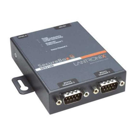
Page 10: Connections And Pinouts
Connections and Pinouts SDS2100 Serial Ports The SDS2100 has two male DB9 DTE serial ports that support RS-232 serial standards up to 115 Kbps. Figure 1-1. Serial Interface Male DB9 Serial Ports... -
Page 11: Network Port
Figure 1-3. Network Interface RJ45 Ethernet Port Power Plug Ethernet Connector Pinouts Figure 1-4. RJ45 Ethernet Connector LEDs The SDS2100 contains the following LEDs: Power 10 Mbps Link/Activity (green) 100 Mbps Link/Activity (green) Diagnostics (red) Status Channel 1 (green) Status Channel 2 (green) Simultaneously lit red and green LEDs mean something is wrong. -
Page 12: Product Information Label
SDS2100 User Guide 1: Introduction Table 1-1. SDS2100 LEDs LEDs Meaning 10 Mbps link/activity steady green Valid 10 Mbps network connection 10 Mbps link/activity blinking Network packets transmitting and receiving 100 Mbps link/activity steady green Valid 100 Mbps network connection... -
Page 13: Technical Specifications
SDS2100 User Guide 1: Introduction Technical Specifications CPU, Memory Lantronix DSTni-LX 186 CPU, 48 MHz 1 MByte FLASH ROM 256 Kbytes zero wait state RAM Serial Interface 2 Male DB9 Connectors (DTE pinout) Speed software selectable (300 to 115 kBaud) -
Page 14: 2: Getting Started
The Ethernet address is also referred to as the hardware address or the MAC address. The first three bytes of the Ethernet Address are fixed and read 00-20-4A, identifying the unit as a Lantronix product. The fourth, fifth, and sixth bytes are unique numbers assigned to each unit. -
Page 15: Physically Connecting The Unit
2: Getting Started Physically Connecting the Unit The following diagram shows a properly installed unit: Figure 2-2. SDS2100 Connected to Serial Device and Network To install the unit, complete the following steps in order. Refer to the numbers in the previous figure. -
Page 16: Methods Of Assigning The Ip Address
Provided a DHCP server exists on the network, it will provide the unit with an IP address, gateway address, and subnet mask when the unit boots up. The SDS2100 has acquired an IP address if the red LED stops flashing and the green Status LED is on continuously. -
Page 17: Autoip
You can manually assign the IP address using the DeviceInstaller, which is on the product CD. Install the DeviceInstaller 1. Insert the product CD into your CD-ROM drive. The Lantronix SDS2100 DeviceServer window displays. 2. If the CD does not launch automatically: 3. -
Page 18: Assign Ip Address And Network Class
SDS2100 User Guide 2: Getting Started Assign IP Address and Network Class 1. Click the Start button on the Task Bar and select Programs Lantronix Device Installer Device Installer. The DeviceInstaller window displays. Figure 2-3. DeviceInstaller Window 2. Click the Assign IP icon... - Page 19 SDS2100 User Guide 2: Getting Started Figure 2-4. Assign IP Address Window (Device Identification) 3. Enter the Hardware or Ethernet address of the device. The following Assign IP Address window appears. Figure 2-5. Assign IP Address Window (Assignment Method) 4. Select Assign a specific IP address to assign a static IP address to the device or select Obtain an IP address automatically to enable BOOTP, DHCP, or Auto IP on the device.
- Page 20 SDS2100 User Guide 2: Getting Started Figure 2-6. Assign IP Address Window (IP Settings) 6. Enter the IP address, subnet mask, and gateway being assigned to the device. Enter this information in XXX.XXX.XXX.XXX format. 7. Click Next. The following Assign IP Address window appears.
-
Page 21: Add The Unit To The Manage List
2: Getting Started Add the Unit to the Manage List Now add the unit to the list of similar Lantronix devices on the network so that you can manage and configure it. To perform this step, click the Search icon: The device should be located by DeviceInstaller and added into the Device List. -
Page 22: Arp And Telnet
SDS2100 User Guide 2: Getting Started ARP and Telnet The unit’s IP address must be configured before a network connection is available. If the unit has no IP address, you can use the Address Resolution Protocol (ARP) method from UNIX and Windows-based systems to assign a temporary IP address. If you want to initially configure the unit through the network, follow these steps: 1. -
Page 23: Serial Port Login
SDS2100 User Guide 2: Getting Started Serial Port Login If you want to initially configure the unit through a serial connection, follow these steps: 1. Connect a console terminal or PC running a terminal emulation program to the unit’s Channel 1 serial port. The default serial port settings are 9600 baud, 8 bits, no parity, 1 stop bit, no flow control. -
Page 24: 3: Configuring The Unit
You must configure the unit so that it can communicate on a network with your serial device. For example, you must set the way the unit will respond to serial and network traffic, how it will handle serial packets, and when to start or close a connection. You can configure your unit locally or remotely using the following procedures: Use a standard Web browser to access the unit’s internal Web pages and configure the unit over the network. - Page 25 SDS2100 User Guide 3: Configuring the Unit Figure 3-2. SDS Configuration Guidelines Page SDS settings opens a configuration window to configure the SDS2100, as shown in Figure 3-3. Serial cabling lets you view pinouts for the SDS serial port. View SDS Configuration Tutorials provide step-by-step instructions for configuring encryption, serial tunneling, and the Com Port Redirector.
- Page 26 SDS2100 User Guide 3: Configuring the Unit Figure 3-3. Lantronix WEB-Manager To configure the unit via a Web browser, select SDS Settings and perform the following steps. 1. Use the menu (pushbuttons) to navigate to sub pages where you can configure server settings.
-
Page 27: Configuring Via The Setup Mode Window
SDS2100 User Guide 3: Configuring the Unit Figure 3-4. Server Properties Configuration on the Web Browser 3. In the Telnet Password field, enter a password to prevent unauthorized access to the Setup Mode via a Telnet connection to port 9999. The password is limited to 4 characters. - Page 28 SDS2100 User Guide 3: Configuring the Unit Note: Be sure to include a space before the IP address and before 9999. 2. Click OK. The Setup Mode window displays. To remain in Setup Mode, you must press Enter within 5 seconds.
-
Page 29: Using The Serial Ports
SDS2100 User Guide 3: Configuring the Unit 5. When you are finished, save the new configurations (option 9). The unit will reboot. For example, to set Channel 1 parameters: Type 1 in the Your choice? field and press Enter. Figure 3-7. Channel 1 Configuration 2. -
Page 30: Server Configuration (Network Configuration)
SDS2100 User Guide 3: Configuring the Unit 3. Select an option on the menu by entering the number of the option in the Your choice ? field and pressing Enter. 4. To enter a value for a parameter, type the value and press Enter, or to confirm a default value, just press Enter. -
Page 31: Change Telnet Configuration Password
SDS2100 User Guide 3: Configuring the Unit Table 3-1. Standard IP Network Netmasks Network Class Host Bits Netmask 255.0.0.0 255.255.0.0 255.255.255.0 Table 3-2. Netmask Examples Netmask Host Bits 255.255.255.252 255.255.255.248 255.255.255.240 255.255.255.224 255.255.255.192 255.255.255.128 255.255.255.0 255.255.254.0 255.255.252.0 255.255.248.0 255.128.0.0 255.0.0.0... -
Page 32: Channel 1 Configuration (Serial Port Parameters)
SDS2100 User Guide 3: Configuring the Unit Channel 1 Configuration (Serial Port Parameters) Using this option, define how the serial port will respond to network and serial communications. Figure 3-10. Channel 1 Configuration Baudrate The unit and attached serial device, such as a modem, must agree on a speed or baud rate to use for the serial connection. -
Page 33: Flow
SDS2100 User Guide 3: Configuring the Unit Table 3-4. Common Interface Mode Settings Common I/F Mode Setting Binary RS-232C, 8-bit, No Parity, 1 stop bit 0100 1100 4C RS-232C, 7-bit, Even Parity, 1 stop bit 0111 1000 78 Flow Flow control sets the local handshake method for stopping serial input/output. - Page 34 SDS2100 User Guide 3: Configuring the Unit Note: If you do not want to convert the binary numbers to hexadecimals yourself, look up the values in Table 6-2. Connect Mode Options in the Binary to Hexadecimal chapter. Table 3-6. Connect Mode Options...
- Page 35 SDS2100 User Guide 3: Configuring the Unit Hostlist: If you enable this option, the Lantronix unit scrolls through the hostlist until it connects to a device listed in the hostlist table. Once it connects, the unit stops trying to connect to any others. If this connection fails, the unit continues to scroll through the table until it is able to connect to another IP in the hostlist.
- Page 36 SDS2100 User Guide 3: Configuring the Unit 5. For Retrytimeout, enter the number of seconds the unit should wait before failing an attempted connection. Modem (Emulation) Mode: In Modem Mode, the unit presents a modem interface to the attached serial device. It accepts AT-style modem commands, and handles the modem signals correctly.
-
Page 37: Remote Ip Address
SDS2100 User Guide 3: Configuring the Unit Modem Mode Command Function Enables or disables connections from the network going to the serial port. n=0 disables the ability to make a connection from the ATS0=n network to the serial port. n=1-9 enables the ability to make a connection from the network to the serial port. -
Page 38: Flush Mode (Buffer Flushing)
SDS2100 User Guide 3: Configuring the Unit Table 3-9. Disconnect Mode Options Disconnect Mode Option Bit 7 6 5 4 3 2 1 0 Disconnect with DSR drop Ignore DSRa Telnet mode and terminal type setup Channel (port) password Hard disconnect... -
Page 39: Disconntime (Inactivity Timeout)
SDS2100 User Guide 3: Configuring the Unit Pack control settings are enabled in Flush Mode. Set this value to 00 if specific functions are not needed. Note: If you do not want to convert the binary numbers to hexadecimals yourself, look up the values in Table 6-7. -
Page 40: Telnet Terminal Type
SDS2100 User Guide 3: Configuring the Unit characters, it is sent immediately, along with any awaiting characters, to the TCP connection. This minimizes the response time for specific protocol characters on the serial line (for example, ETX, EOT, etc.). Setting the first sendchar to 00 disables the recognition of the characters. -
Page 41: Tcp Keepalive Time In S
SDS2100 User Guide 3: Configuring the Unit TCP Keepalive time in s This option allows you to change how many seconds the unit will wait during a silent connection before attempting to see if the currently connected network device is still on the network. -
Page 42: Disable Telnet Setup
Disable Port 77FE (Hex) Port 77FE is a setting that allows the Lantronix Device Installer utility to configure the unit remotely. Disabling Port 77FE will prevent remote access to the unit from the Lantronix Device Installer utility. You can configure the unit only by using Web pages, Telnet, or serial configuration. - Page 43 AES encryption protocols. To communicate successfully, products and applications on the peer side must use the same protocols and the same shared key as the SDS. To ease the development process, Lantronix provides an AES encryption DLL for Windows and protocol source code samples.
-
Page 44: Factory Default Settings
SDS2100 User Guide 3: Configuring the Unit Factory Default Settings Select 7 to reset the unit’s serial port to the factory default settings. The server configurations (IP address information) remain unchanged. Exit Configuration Mode Select 8 to exit the configuration mode without saving any changes or rebooting, OR... -
Page 45: 4: Updating Firmware
Obtaining Firmware You can obtain the most up-to-date firmware and release notes for the unit from the Lantronix Web site (http://www.lantronix.com/) or by using anonymous FTP (ftp://ftp.lantronix.com/). Reloading Firmware There are several ways to update the unit's internal operational code (SDS*.ROM or SD21*.HEX): via DeviceInstaller (the preferred way), via TFTP, via another unit, or... - Page 46 SDS2100 User Guide 4. Updating Firmware 3. Click the Search the network for devices icon. The Search Network window displays. Figure 4-2. Search Network Window 4. Once located by DeviceInstaller, highlight the device in the device list and click the Upgrade button (which displays after you select the device). Select a custom installation by specifying the individual files and clicking Next.
-
Page 47: Via Tftp
SDS2100 User Guide 4. Updating Firmware Figure 4-4. Device Upgrade Wizard (Window 2) 6. Select Do not copy or replace any files and click Next. 7. Click Next again. The status of the upgrade is shown in the window. 8. After the upgrade completes, click Close. -
Page 48: Via Another Unit
SDS2100 User Guide 4. Updating Firmware Figure 4-5. TFTP Dialog Box C:\SDSxxxx.ROM 172.19.23.55 The unit performs a power reset after the firmware has been loaded and stored. Via Another Unit To distribute firmware to another unit over the network: 1. Enter the host unit's Monitor Mode (see... -
Page 49: Via The Serial Port
SDS2100 User Guide 4. Updating Firmware Via the Serial Port The following procedure is for using the HyperTerminal software application. This procedure takes about 10 minutes. Note: Do not switch off the power supply during the update. A loss of power while reprogramming will result in a corrupt program image and a nonfunctional unit. - Page 50 SDS2100 User Guide 4. Updating Firmware...
-
Page 51: 5: Troubleshooting
This chapter discusses how you can diagnose and fix errors quickly without having to contact a dealer or Lantronix. It helps to connect a terminal to the serial port while diagnosing an error to view summary messages that may be displayed. When troubleshooting, always ensure that the physical connections (power cable, network cable, and serial cable) are secure. - Page 52 SDS2100 User Guide 5.Troubleshooting When you report a problem, please provide the following information: Your name, your company name, address, and phone number Lantronix SDS model number Lantronix SDS serial number Software version (on the first screen shown when you Telnet to port 9999)
- Page 53 If this does not fix the problem, into power properly. contact your dealer or Lantronix Technical Support for a replacement. The SDS2100 will not power up Various Consult the LEDs section in the properly, and the LEDs are flashing.
- Page 54 SDS2100 User Guide 5.Troubleshooting Problem/Message Reason Solution You can ping the SDS, but not There may be an IP address conflict Turn the SDS off and then issue the Telnet to the SDS on port 9999. on your network following commands at the DOS prompt of your computer: ARP -D You are not Telneting to port 9999.
-
Page 55: Monitor Mode
To enter Monitor Mode using a Telnet connection: 1. First establish a Telnet session. The following message displays: Figure 5-1. Entering Monitor Mode Via the Network *** Lantronix Secure Device Server *** MAC address 00204A0250AF Software Version 05.6b3 <040311> SDS2100 AES library version 1.8.2.1... - Page 56 SDS2100 User Guide 5.Troubleshooting Table 5-2. Monitor Mode Commands Command Command Name Function SF x.x.x.x Send Firmware Sends firmware to unit with IP address x.x.x.x Queries software header record (16-byte) of unit with IP address VS x.x.x.x Version x.x.x.x GC x.x.x.x Get Configuration Gets configuration of unit with IP address x.x.x.x as hex records...
-
Page 57: 6: Binary To Hexadecimal
Many of the unit 's configuration procedures require you to assemble a series of options (represented as bits) into a complete command (represented as a byte). The resulting binary value must be converted to a hexadecimal representation. Use this chapter to learn how to convert binary values to hexadecimals or to look up values in the tables listing all configuration options in hexadecimal notation. -
Page 58: Connect Mode Options
SDS2100 User Guide 6. Binary to Hexadecimal Table 6-1. Binary to Hexadecimal Conversions Decimal Binary Hex 0000 0001 0010 0011 0100 0101 0110 0111 1000 1001 1010 1011 1100 1101 1110 1111 Connect Mode Options Note: Character response codes are C=conn, D=disconn, N=unreachable Table 6-2. - Page 59 SDS2100 User Guide 6. Binary to Hexadecimal Accept Incoming Serial Active Connection Hostlist Connections Response Upon Startup Connection With DSR None (quiet) With DSR Character No active startup With DSR Character Any character With DSR Character Active DSR With DSR...
- Page 60 SDS2100 User Guide 6. Binary to Hexadecimal Accept Incoming Serial Active Connection Hostlist Connections Response Upon Startup Connection With DSR Character Autostart Hostlist With DSR Character Hostlist Unconditionally None (quiet) No active startup Hostlist Unconditionally None (quiet) Any character Hostlist...
-
Page 61: Disconnect Mode Options
SDS2100 User Guide 6. Binary to Hexadecimal The following connect mode options are for when you use modem emulation: Table 6-3. Connect Mode Options for Modem Emulation Accept Incoming Response Connections Never Echo Never Without echo Never 1-character response With DSR... - Page 62 SDS2100 User Guide 6. Binary to Hexadecimal Disconnect with Telnet Mode Channel (port) Hard State LED Off Disconnect DSR Drop and Terminal Password Disconnect with with EOT (^D) Type Setup Connection Enable Enable Enable Enable Enable Enable Enable Enable Enable...
-
Page 63: Flush Mode (Buffer Flushing) Options
SDS2100 User Guide 6. Binary to Hexadecimal Flush Mode (Buffer Flushing) Options Table 6-5. Flush Mode Options Serial to Network Network to Serial Alternate Packing Clear input buffer upon: Clear output buffer upon: Algorithm None Active connection Passive connection Active connection... - Page 64 SDS2100 User Guide 6. Binary to Hexadecimal Serial to Network Network to Serial Alternate Packing Clear input buffer upon: Clear output buffer upon: Algorithm Passive connection Active connection Enable Disconnect Active connection Active connection Enable Passive connection Disconnect Passive connection...
- Page 65 SDS2100 User Guide 6. Binary to Hexadecimal Serial to Network Network to Serial Alternate Packing Clear input buffer upon: Clear output buffer upon: Algorithm Active connection Active connection Enable Passive connection Passive connection Disconnect Active connection Enable Passive connection Active connection...
- Page 66 SDS2100 User Guide 6. Binary to Hexadecimal Serial to Network Network to Serial Alternate Packing Clear input buffer upon: Clear output buffer upon: Algorithm Active connection Enable Disconnect Active connection Active connection Enable Disconnect Passive connection Active connection Enable Disconnect...
- Page 67 SDS2100 User Guide 6. Binary to Hexadecimal Serial to Network Network to Serial Alternate Packing Clear input buffer upon: Clear output buffer upon: Algorithm Passive connection Active connection Passive connection Disconnect Active connection Active connection Passive connection Passive connection Disconnect...
-
Page 68: Interface Mode Options
SDS2100 User Guide 6. Binary to Hexadecimal Interface Mode Options Table 6-6. Interface Mode Options Interface Bits Parity Stop Bits RS-232C RS-232C RS-232C Even RS-232C Even RS-232C RS-232C RS-232C RS-232C RS-232C Even RS-232C Even RS-232C RS-232C... -
Page 69: Pack Control Options
SDS2100 User Guide 6. Binary to Hexadecimal Pack Control Options Table 6-7. Pack Control Options Sendcharacter Trailing Idle Time Send Immediately Defined by a: Characters Force Transmit: after Sendcharacter 1-Byte Sequence 12ms 1-Byte Sequence 52ms 1-Byte Sequence 250ms 1-Byte Sequence... - Page 70 SDS2100 User Guide 6. Binary to Hexadecimal Sendcharacter Trailing Idle Time Send Immediately Defined by a: Characters Force Transmit: after Sendcharacter 2-Byte Sequence 12ms 2-Byte Sequence 52ms 2-Byte Sequence 250ms 2-Byte Sequence 5sec...
Need help?
Do you have a question about the SecureBox SDS2100 and is the answer not in the manual?
Questions and answers