Table of Contents
Advertisement
Quick Links
Advertisement
Table of Contents

Related Manuals for Lantronix SDS1101


Summary of Contents for Lantronix SDS1101
- Page 1 SDS1101/2101 User Guide Part Number 900-451 Revision C February 2010...
- Page 2 Copyright & Trademark © 2009 and 2010, Lantronix. All rights reserved. No part of the contents of this book may be transmitted or reproduced in any form or by any means without the written permission of Lantronix. Printed in the United States of America.
- Page 3 Revisions Date Rev. Comments 8/06 Initial document 1/09 Include SDS2101 product; updated to firmware v6.5.0.0 2/10 Update document with corrections. SDS1101/2101 User Guide...
-
Page 4: Table Of Contents
Installing DeviceInstaller __________________________________________ 18 Assigning an IP Address __________________________________________ 18 Adding the Unit to the Manage List __________________________________ 19 Accessing the SDS1101/2101 Using DeviceInstaller ____________________ 19 Viewing the Current Configuration ___________________________________ 19 Next Step ______________________________________________________ 21 Assigning the IP Address: Serial Port Login _______________________________ 21... - Page 5 HTTP Port Number ______________________________________________ 60 MTU Size ______________________________________________________ 60 Enable alternate MAC ____________________________________________ 60 Ethernet connection type __________________________________________ 60 Security Settings (Option 6) ___________________________________________ 60 Disable SNMP __________________________________________________ 61 SNMP Community Name __________________________________________ 61 Disable Telnet Setup _____________________________________________ 61 SDS1101/2101 User Guide...
- Page 6 SDS1101 LEDs ____________________________________________________ 71 SDS2101 LEDs ____________________________________________________ 72 Problems and Error Messages _________________________________________ 72 Technical Support ___________________________________________________ 74 12: SDS1101 Connections and Pinouts Serial Port _____________________________________________________ 76 Serial Connector Pinouts __________________________________________ 76 Modem Cable ___________________________________________________ 77 Network Port ___________________________________________________ 78...
- Page 7 Figure 2-1. Serial Tunneling Example _____________________________________ 12 Figure 2-2. Direct TCP/IP or Redirector Configuration _________________________ 12 Figure 2-3. Sample Hardware Address ____________________________________ 14 Figure 3-1. SDS1101 Connected to Serial Device and Network _________________ 16 Figure 4-1. Lantronix Web-Manager ______________________________________ 24 Figure 4-2. Network Settings ____________________________________________ 24 Figure 4-3.
- Page 8 Table 10-2. Command Response Codes ___________________________________ 70 Table 11-1. SDS1101 LEDs _____________________________________________ 71 Table 11-2. SDS2101 LEDs _____________________________________________ 72 Table 11-3. Problems and Error Messages _________________________________ 72 Table 14-1. SDS1101 Technical Specifications ______________________________ 82 Table 15-1. SDS2101 Technical Specifications ______________________________ 84 SDS1101/2101 User Guide...
-
Page 9: 1: Using This Guide
Purpose and Audience This guide provides the information needed to configure, use, and update the SDS1101 & SDS2101 device servers. It is for system administrators and those responsible for installing and maintaining the SDS. Chapter Summary The remaining chapters in this guide include:... -
Page 10: Additional Documentation
SDS1101 & SDS2101 Quick Start Provides the steps for getting the SDS1101/2101 up and running. DeviceInstaller Online Help Provides instructions for using the Windows-based utility to configure the SDS1101/2101 and other Lantronix device servers. -
Page 11: 2: Introduction
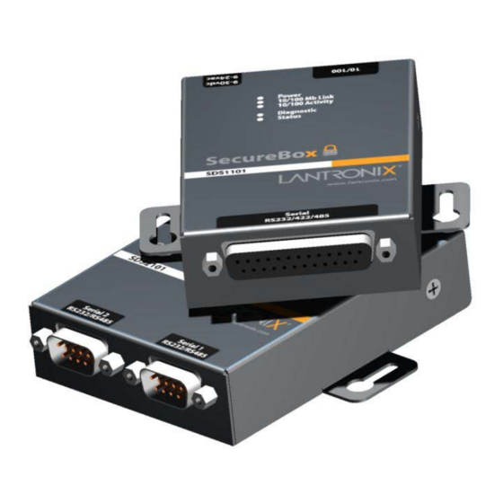
The SDS1101 is a single-port device server and the SDS2101 is a dual port device server that provide a quick, simple, and cost-effective way to bring the advantages of data accessibility and remote management to devices not currently connected to a network. -
Page 12: Figure 2-1. Serial Tunneling Example
Figure 2-2. Direct TCP/IP or Redirector Configuration Device Server Note: For step-by-step instructions on configuring the SDS for serial tunneling or for use with the Com Port Redirector, see SDS Configuration Tutorials on the Lantronix web site: www.lantronix.com/support. SDS1101/2101 User Guide... -
Page 13: Protocol Support
Setup Mode: making a Telnet connection to the network port (9999) or connecting a terminal (or a PC running a terminal emulation program) to the unit’s serial port. (See 5: Configuration via Telnet or Serial Port (Setup Mode). SDS1101/2101 User Guide... -
Page 14: Product Information Label
Hardware address (also referred to as the Ethernet or MAC address) The first three bytes of the hardware address are fixed and read 00-20-4A, identifying the unit as a Lantronix product. The fourth, fifth, and sixth bytes are unique numbers assigned to each unit. -
Page 15: 3: Getting Started
This chapter describes how to get your SDS up and running in the shortest possible time. Package Contents Verify and inspect the contents of the SDS1101/2101 package using the following list. If any item is missing or damaged, contact your place of purchase immediately. ... -
Page 16: Installing The Sds
3: Getting Started Installing the SDS Figure 3-1. SDS1101 Connected to Serial Device and Network To install the unit: Complete the following steps in order. Refer to the numbers in the figure above. Note: See the sections that follow for details about connectors and pinouts. -
Page 17: Required Information
This chapter provides information about using the DeviceInstaller (graphical user interface) and serial port login (command line interface) methods. Note: For information about other methods of assigning the IP address, such as DHCP, AutoIP, ARP, and Telnet, see Alternative Ways to Assign an IP Address. SDS1101/2101 User Guide... -
Page 18: Assigning The Ip Address: Deviceinstaller
3: Getting Started Assigning the IP Address: DeviceInstaller This chapter covers the steps for getting the SDS1101/2101 device server online and for viewing its current configuration. Note: DeviceInstaller online Help provides more detailed information on using DeviceInstaller. Installing DeviceInstaller To use the DeviceInstaller utility, first install it from the product CD. -
Page 19: Adding The Unit To The Manage List
9. Click the Close button to close the dialog box and return to the main window. Adding the Unit to the Manage List Now add the unit to the list of similar Lantronix devices on the network so you can manage and configure it. To perform this step, click the Search icon DeviceInstaller locates the unit and adds it to the list. - Page 20 3: Getting Started Device Family Non-configurable field. Displays the SDS1101’s and SDS2101’s device family type as SDS. Type Non-configurable field. Displays the device type as SDS1101 or SDS2101. Non-configurable field. Displays the SDS’s ID embedded within the box. Hardware Address Non-configurable field.
-
Page 21: Next Step
Stream Supports 485 Non-configurable field. Displays True. The SDS supports the RS-485 protocol. Non-configurable field. Displays False for SDS1101 which Supports 920K Baudrate supports baud rates up to 230400. Displays True for SDS2101 which supports a baud rate of 921600. - Page 22 4. Enter the new IP address, subnet mask, and gateway (if applicable). 5. Do one of the following: Continue with 5: Configuration via Telnet or Serial Port (Setup Mode). Select 9 to save and exit Setup Mode. The unit performs a power reset. SDS1101/2101 User Guide...
-
Page 23: 4: Configuration Using Web-Manager
2. Click the SDS folder. The list of available SDS products displays. 3. Expand the list of SDS1101s by clicking the + symbol next to the SDS1101 icon. Likewise, expand the list of SDS2101s by clicking the + symbol next to the SDS2101 icon. -
Page 24: Network Configuration
4: Configuration Using Web-Manager Figure 4-1. Lantronix Web-Manager The main menu is in the left pane of the Web-Manager window for both the SDS1101 and SDS2101. Network Configuration The unit’s network values display when you select Network from the main menu. The following sections describe the configurable parameters on the Network Settings page. -
Page 25: Automatic Ip Address Configuration
The gateway address, or router, allows communication to other LAN segments. The gateway address should be the IP address of the router connected to the same LAN segment as the unit. The gateway address must be within the local network. SDS1101/2101 User Guide... -
Page 26: Ethernet Configuration
3. When you are finished, click the OK button. 4. On the main menu, click Apply Settings. Server Configuration The unit’s server values display when you select Server from the main menu. The following sections describe the configurable parameters on the Server Settings page. SDS1101/2101 User Guide... -
Page 27: Figure 4-3. Server Settings
TCP Keepalive time defines how many seconds the unit waits during an inactive connection before checking its status. If the unit does not receive a response, it drops that connection. Enter a value between 0 and 60 seconds. 0 disables keepalive. The default setting is 45. SDS1101/2101 User Guide... -
Page 28: Host List Configuration
The host list is disabled for Manual and Modem Mode. The unit does not accept a data connection from a remote device when the hostlist option is enabled. To configure the host list: 1. On the main menu, click Hostlist. SDS1101/2101 User Guide... -
Page 29: Channel 1 & Channel 2 (Sds2101 Only) Configuration
4. On the main menu, click Apply Settings. Channel 1 & Channel 2 (SDS2101 only) Configuration The Channel configuration defines how the serial port responds to network and serial communication. Serial Settings To configure the channel’s serial settings: SDS1101/2101 User Guide... -
Page 30: Figure 4-5. Channel Serial Settings
Valid baud rates are 300, 600, 1200, 2400, 4800, 9600 (default), 19200, 38400, 57600, 115200, and 230400 baud. The SDS2101 also supports 460800 and 921600 baud. The SDS1101/2101 User Guide... - Page 31 The default setting is No. At Time of Disconnect Select Yes to clear the input buffer when the network connection to or from the device is disconnected. The default setting is No. SDS1101/2101 User Guide...
-
Page 32: Connection Settings - Tcp
3. When you are finished, click the OK button. 4. On the main menu, click Apply Settings. Connection Settings - TCP To configure a channel’s TCP settings: 1. On the main menu, click Connection. The Connection Settings window for the channel displays. SDS1101/2101 User Guide... -
Page 33: Figure 4-6. Tcp Connection Settings
Determines whether a password is required for an incoming passive connection. This field is not available when a password is set for Telnet mode. The default setting is No. Password If Password Required was set to Yes, enter the password for passive connections. SDS1101/2101 User Guide... - Page 34 Com Port Redirector (CPR) utility. (See the CPR online Help for details.) Terminal Name This field is available for configuration only when Telnet Com Port Cntrl is set to Enable. SDS1101/2101 User Guide...
-
Page 35: Connection Settings - Udp
Set to Yes for the network connection to or from the serial port On Mdm_Ctrl_In Drop to disconnect (drop) when Modem Control In (DSR for SDS1101) transitions from a high state to a low state. The default setting is No. When set to Yes, the TCP connection closes even if the Hard Disconnect remote site does not acknowledge the disconnect request. -
Page 36: Figure 4-7. Udp Connection Settings
Enter 01 for directed or broadcast UDP. The default setting is 00. Accept Incoming Select Yes to accept incoming UDP datagrams. The default setting is Yes. Endpoint Configuration Local Port Enter the local port number. SDS1101/2101 User Guide... -
Page 37: Apply Settings
1 and 255 to identify units on the local network of device servers. Note: Lantronix Tech Support supports Datagram type 01. Datagram Type FD is for OEM use. 3. When you are finished, click the OK button. 4. On the main menu, click Apply Settings. -
Page 38: 5: Configuration Via Telnet Or Serial Port (Setup Mode)
1. From the Windows Start menu, click Run and type the following command, where x.x.x.x is the IP address, and 9999 is the unit’s fixed network configuration port number: Windows: telnet x.x.x.x 9999 UNIX: telnet x.x.x.x 9999 2. Click OK. The following information displays. SDS1101/2101 User Guide... -
Page 39: Serial Port Connection
At this point, the screen display is the same as when you use a Telnet connection. To continue, go to step 3 in Telnet Connection, above. Exiting Setup Mode To exit setup mode, use one of the following two options: SDS1101/2101 User Guide... - Page 40 To save all changes and reboot the device, select option 9 Save and exit from the Change Setup menu. All values are stored in nonvolatile memory. To exit the configuration mode without saving any changes or rebooting. select option 8 Exit without save from the Change Setup menu. SDS1101/2101 User Guide...
-
Page 41: 6: Setup Mode: Server Configuration
The gateway address, or router, allows communication to other LAN segments. The gateway address should be the IP address of the router connected to the same LAN segment as the unit. The gateway address must be within the local network. The SDS1101/2101 User Guide... -
Page 42: Netmask: Number Of Bits For Host Part
DeviceInstaller network search feature or Monitor Mode (see 10: Monitor Mode). Note: When you enter Monitor Mode from the serial port with network connection enabled and issue the NC (Network Communication) command, you see the unit’s IP configuration. SDS1101/2101 User Guide... - Page 43 YY is what you chose for the last octet of the IP address. If the IP address you specify is 0.0.0.12, then the DHCP name is LTX12. This method only works with 2 digit numbers (01-99). SDS1101/2101 User Guide...
-
Page 44: 7: Setup Mode: Channel Configuration
Valid baud rates are 300, 600, 1200, 2400, 4800, 9600 (default), 19200, 38400, 57600, 115200, and 230400 baud. The SDS2101 also supports 460800 and 921600 baud. Baudrate (9600) ? _ SDS1101/2101 User Guide... -
Page 45: I/F (Interface) Mode
RS-485 2-wire, 8-bit, No Parity, 1 stop bit 0100 1111 RS-422, 8-bit, Odd Parity, 1 stop bit 0101 1101 Flow Flow control sets the local handshaking method for stopping serial input/output. The default setting is 00. Flow (00) ? _ SDS1101/2101 User Guide... -
Page 46: Port Number
Enter Connect Mode options in hexadecimal notation. The default setting is C0. Note: All bit positions in the table that are blank represent “don’t care” bits for that particular option, which can be set to either a 0 or 1 value. SDS1101/2101 User Guide... -
Page 47: A) Incoming Connection
Rejects all external connection attempts. Accept with DTR Active Accepts external connection requests only when the DTR input is asserted. Cannot be used with Modem Mode. Always Accept Accepts any incoming connection when a connection is not SDS1101/2101 User Guide... -
Page 48: B) Response
129.1.2.3, then an example command string would be C3/7. (This would connect to 129.1.2.3 and port 7.) You may also use a different ending for the connection string. For example, C50.1/23 would connect you to 129.1.50.1 and port 23. SDS1101/2101 User Guide... -
Page 49: Table 7-6. Manual Connection Address Example
Each entry contains the IP address and the port number. The hostlist is disabled for Manual and Modem Modes. The unit does not accept a data connection from a remote device when the hostlist option is enabled. SDS1101/2101 User Guide... -
Page 50: Figure 7-2. Hostlist Option
7: Setup Mode: Channel Configuration Figure 7-2. Hostlist Option SDS1101/2101 User Guide... -
Page 51: D) Datagram Type
3. After completing the hostlist, repeat the previous step if necessary to edit the hostlist again. 4. For Retrycounter, enter the number of times the Lantronix unit should try to make a good network connection to a hostlist entry that it has successfully ARPed. -
Page 52: Table 7-7. Modem Mode Messages
"OK" message and takes no further action. If the Numeric Response option is in effect, the unit responds to an unrecognized command string that is otherwise formatted correctly with a "0" message and takes no further action. SDS1101/2101 User Guide... -
Page 53: Table 7-8. Modem Mode Commands
Enables or disables character echo and responses. ATEn n=0 disables character echo and responses. n=1 enables character echo and responses. Enables numeric response or full verbose. ATVn n=0 enables numeric response. n=1 enables full verbose. SDS1101/2101 User Guide... -
Page 54: Send The Escape Sequence (+++) In Modem Mode
This option does not display when Hostlist is enabled from the ConnectMode prompt (see Connect Mode for more information). DisConnMode This setting determines the conditions under which the unit will cause a network connection to terminate. The default setting is 00. SDS1101/2101 User Guide... -
Page 55: Flush Mode (Buffer Flushing)
You can also select between two different packing algorithms. Note: All bit positions in the table that are blank represent “don’t care” bits for that particular option, which can be set to either a 0 or 1 value. SDS1101/2101 User Guide... -
Page 56: Pack Control
0 or 1 value. Table 7-11. Pack Control Options Option Packing Interval Interval: 12 msec Interval: 52 msec Interval: 250 msec Interval: 5 sec Trailing Characters None Send Characters SDS1101/2101 User Guide... -
Page 57: Packing Interval
TCP connection. This action minimizes the response time for specific protocol characters on the serial line (for example, ETX, EOT). Setting the first sendchar to 00 SDS1101/2101 User Guide... -
Page 58: Telnet Terminal Type
Channel (Port) Password This parameter appears only if the channel (port) password option is enabled in Disconnect Mode. With this option enabled, you can set a password on the serial port. The default setting is all 0s. SDS1101/2101 User Guide... -
Page 59: 8: Setup Mode: Advanced Settings
CPU performance (0=Regular, 1=Low, 2=High): (0) Disable Monitor Mode at bootup This option allows you to disable all entries into Monitor Mode during startup, except for the ‘xxx’ sequence. This prevents entry using yyy, zzz, xx1, and yy1 key SDS1101/2101 User Guide... -
Page 60: Http Port Number
Caution: Disabling both Telnet Setup and Port 77FE will prevent users from accessing the setup menu from the network. Disabling Port 77FE also disables the Web from configuring the device. Select 6 to configure security settings. SDS1101/2101 User Guide... -
Page 61: Disable Snmp
This setting defaults to the N (No) option. The Y (Yes) option disables the use of TFTP to perform network firmware upgrades. With this option, you can download firmware upgrades over the serial port using DeviceInstaller’s Recover Firmware procedure. (See 9: Firmware Upgrades.) Disable TFTP Firmware Update (N) : SDS1101/2101 User Guide... -
Page 62: Disable Port 77Fe (Hex)
Technology (NIST) as the Advanced Encryption Standard (AES) to be used by the US government. The SDS supports 128-, 192-, and 256-bit encryption key lengths. NOTE: Configuring encryption should be done through a local connection to the serial port of the SDS, or via a secured network connection. Initial SDS1101/2101 User Guide... -
Page 63: Figure 8-3. Encryption Keys
Third-party application to SDS-encrypted communication: SDS uses standard AES encryption protocols. To communicate successfully, products and applications on the peer side must use the same protocols and the same encryption key as the SDS. Developers can license the Lantronix Encryption Library suite. ... -
Page 64: Default Settings (Option 7)
Hostlist retry timeout 250 (msec) Start character for serial channel 2 0x0D (CR) All other parameters Expert Settings Defaults TCP Keepalive time in s ARP Cache timeout in s Disable Monitor Mode @ bootup HTTP Port Number SDS1101/2101 User Guide... -
Page 65: Security Settings Defaults
Ethernet Connection Type 0 (auto-negotiate) Security Settings Defaults Disable SNMP SNMP community name public Disable Telnet setup Disable TFTP Firmware Update Disable Port 77FEh Disable Web Server Disable Web Setup Disable ECHO ports Enable Encryption Enable Enhanced Password SDS1101/2101 User Guide... -
Page 66: 9: Firmware Upgrades
DeviceInstaller (the preferred way), using TFTP, or using the serial port. You can also update the unit's internal Web interface (*.COB) using TFTP or DeviceInstaller. Here are typical names for those files. Check the Lantronix web site for the latest versions and release notes. -
Page 67: Using Tftp: Command Line Interface
If for some reason the firmware is damaged, you can recover the firmware file by using DeviceInstaller to download the *.ROM file over the serial port. To recover firmware: 1. Start DeviceInstaller. If your PC has more than one network adapter, a message displays. Select an adapter and click OK. SDS1101/2101 User Guide... - Page 68 3. For Port on PC, enter the COM port on the PC that is connected to the serial port of the Lantronix unit. 4. For Device Model, be sure the appropriate device (e.g. SDS1101) displays. 5. For Firmware File, click the Browse button and go to the location where the firmware file resides.
-
Page 69: 10: Monitor Mode
IP address. If you do not enter the IP address, the command is executed locally. Note: All commands must be in capital letters. Responses to some of the commands are in Intel Hex format. SDS1101/2101 User Guide... -
Page 70: Table 10-1. Monitor Mode Commands
Entering any of the commands listed above generates one of the following command response codes: Table 10-2. Command Response Codes Response Meaning 0> OK; no error 1> No answer from remote device 2> Cannot reach remote device or no answer 8> Wrong parameter(s) 9> Invalid command SDS1101/2101 User Guide... -
Page 71: 11: Troubleshooting And Contact Information
This chapter discusses how you can diagnose and fix errors quickly without having to contact a dealer or Lantronix. It helps to connect a terminal to the serial port while diagnosing an error to view summary messages that may display. When troubleshooting, always ensure that the physical connections (power cable, network cable, and serial cable) are secure. -
Page 72: Sds2101 Leds
Have someone from your IT command in Windows, the "ARP user does not have the department log you in with sufficient entry addition failed: 5" message correct rights to use this rights. displays. command on this PC. SDS1101/2101 User Guide... - Page 73 The default serial settings for the device server are RS-232, 9600 baud, 8 character bits, no parity, 1 stop bit, no flow control. SDS1101/2101 User Guide...
-
Page 74: Technical Support
SDS. The device server appears to be If you are sure that the On SDS1101 you can check to see set up correctly, but you are not serial port setting is whether there is a socket connection... - Page 75 Software version (on the first screen shown when you Telnet to port 9999) Description of the problem Status of the unit when the problem occurred (please try to include information on user and network activity at the time of the problem) SDS1101/2101 User Guide...
-
Page 76: 12: Sds1101 Connections And Pinouts
Serial Port The SDS1101 has a female DCE DB25 serial port that supports RS-232 and RS- 485/422 serial standards (software selectable) up to 230 Kbaud. Figure 12-1. Serial Interface DB25 Serial Port Serial Connector Pinouts The unit’s female DB25 connector provides an RS-232C, RS-485, or RS-422 DCE serial port. -
Page 77: Modem Cable
Figure 12-4. DB25 Female Interface RS485 (2 wire mode) Modem Cable When attaching the DB25 of the SDS1101 to the DB9 com port on a PC, use a standard straight-through serial cable. The figure below shows the pinouts for a DB25 to DB9 straight-through cable, often referred to as a "Modem Cable". -
Page 78: Network Port
12: SDS1101 Connections and Pinouts Figure 12-5. Modem Cable Network Port The unit's back panel contains a power plug and an RJ45 (10/100) Ethernet port. Figure 12-6. Network Interface RJ45 Ethernet Port Power Plug SDS1101/2101 User Guide... -
Page 79: Ethernet Connector Pinouts
12: SDS1101 Connections and Pinouts Ethernet Connector Pinouts The SDS1101 supports 10/100 Mbps half or full duplex Ethernet through an RJ45 connector. Figure 12-7. RJ45 Ethernet Connector Power Plug Power input on the power plug is 9 -30 VDC (center +) or 10-24 VAC (1.5W maximum power required). -
Page 80: 13: Sds2101 Connections And Pinouts
The two Male DB9 DTE connectors provide an RS-232C/RS-422 (4-wire)/ RS-485 (2-wire) interface. The default serial port settings are 9600 baud, 8 bits, no parity, 1 stop bit, no flow control. Figure 13-2. DB9 Male RS232 Serial DTE Connector SDS1101/2101 User Guide... -
Page 81: Network Port
2. Release the button and remove the paper clip. The firmware restores factory default settings to the configuration and invokes a reset (internally). Ethernet Connector Pinouts Power Plug Power input on the power plug is 9-30 VDC (center +) (1.8W maximum power). SDS1101/2101 User Guide... -
Page 82: 14: Sds1101 Technical Specifications
0.20 kg (0.45 lb) Temperature Operating range: 0° to 60° C (32° to 140° F) Note: Operating range for SDS1101-IAP only: -40° to 70° C (-40° to 158° F) Storage -40° to 85° C (-40 to 185° F) Relative Humidity... - Page 83 14: SDS1101 Technical Specifications Category Description Telnet login DeviceInstaller software System Software DeviceInstaller, Windows® 95/98/ME/NT/2000/XP-based configuration software Com Port Redirector, Windows® 98/NT/2000/XP-based virtual com port software LEDs Power 10/100 Mb Link 10/100 Activity Diagnostic Status Emissions FCC Part 15 Subpart B Class A Radiated Emissions 30MHz –...
-
Page 84: 15: Sds2101 Technical Specifications
Table 15-1. SDS2101 Technical Specifications Category Description Lantronix DSTNI-EX 48 MHz clock Internal CPU 256 KB zero wait state SRAM Memory Flash 2 MB Flash EEPROM 2 KB EEPROM Serial Interface 2 DB9M DTE serial ports Software-selectable baud rate from 300 to 921K baud (when High... - Page 85 25 periods), (>95%, 250 periods) Isolation Designed with protections against transients and ESD for use under harsh environments Serial Port: 15 KV ESD protection on RS232 and RS422/485 transceivers Power Input: Up to non-repeated 600 W 10/100 usec pulse protection against SDS1101/2101 User Guide...
- Page 86 15: SDS2101 Technical Specifications Category Description transient over voltages Ethernet Port: 1500 VAC isolation shielded with shield connected to chassis ground for signal integrity and ESD protection Agency Approvals UL, CSA, FCC, CE, TUV, CTick, VCCI SDS1101/2101 User Guide...
-
Page 87: A: Alternative Ways To Assign An Ip Address
If a DHCP server is found, but it denies the request for an IP address, the unit does not attach to the network, but waits and retries. AutoIP can be disabled by setting the unit’s IP address to 0.0.1.0. This setting enables DHCP but disables AutoIP. SDS1101/2101 User Guide... -
Page 88: Bootp
191.12.3.77 9999 Note: The IP address you just set is temporary and reverts to the default value when the unit’s power is reset, unless you configure the unit with a static IP address and store the changes permanently. SDS1101/2101 User Guide... -
Page 89: B: Binary To Hexadecimal Conversions
(in this case, 4C). Use the following table to convert values from binary to hexadecimal. Decimal Binary 0000 0001 0010 0011 0100 0101 0110 0111 1000 1001 1010 1011 1100 1101 1110 1111 SDS1101/2101 User Guide... -
Page 90: Scientific Calculator
Windows’ operating systems. For example: 1. On the Windows’ Start menu, click ProgramsAccessoriesCalculator. 2. On the View menu, select Scientific. The scientific calculator displays. 3. Select Bin (Binary), and type the number to convert. 4. Click Hex. The hexadecimal value displays. SDS1101/2101 User Guide... -
Page 91: C: Warranty
For details on the Lantronix warranty replacement policy, please go to our Web site at www.lantronix.com/support/warranty. SDS1101/2101 User Guide... -
Page 92: D: Compliance And Disclaimer
Manufacturer’s Name & Address Lantronix 167 Technology Drive Irvine, CA 92618 USA Declares that the following product: Product Name Model: SDS1101 and SDS2101 Device Servers Conforms to the following standards or other normative documents: Safety UL 60950-1 CSA 22.2. No 60950-1-03 EN 60950-1... - Page 93 D:Compliance and Disclaimer IEC 61000-4-11: 1994 RoHS Notice All Lantronix products in the following families are China RoHS-compliant and free of the following hazardous substances and elements: • • • Lead (Pb) Mercury (Hg) Polybrominated biphenyls (PBB) • • •...
- Page 94 D:Compliance and Disclaimer Manufacturer’s Contact 167 Technology Drive Irvine, CA 92618 USA Toll Free: 800-526-8766 Phone: 949-453-3990 Fax: 949-450-7249 SDS1101/2101 User Guide...
-
Page 95: Index
Installation, 16 accessing by serial port connection, 39 Internal web server, 13 accessing by Telnet. See IP address SNMP, 61 assigning, 18, 25, 41 TCP settings, 32 automatic assignment, 25 Technical specifications factory default, 17 Technical Support, 74 SDS1101/2101 User Guide... - Page 96 TFTP, 66 Warranty, 91 Troubleshooting, 9, 71 Web-Manager, 23 UDP settings, 35 SDS1101/2101 User Guide...
Need help?
Do you have a question about the SDS1101 and is the answer not in the manual?
Questions and answers