Lantronix SGX 5150 Manual
Serial device server
Hide thumbs
Also See for SGX 5150:
- User manual (142 pages) ,
- Quick start manuals (2 pages) ,
- Command reference manual (372 pages)
Table of Contents
Advertisement
Quick Links
5 Gould Road, PO Box 2155
New London, NH 03257 USA
Voice: (603) 526-9800
info@canarysystems.com
www.canarysystems.com
Using the Lantronix SGX 5150 Serial Device Server
Application Note #28 - Revision 01/2021
Overview
The Lantronix
industrial wireless device serial servers and Ethernet Bridge/Routers are built for networking
equipment in an array of machine-to-machine (M2M) applications. The SGX 5150 features an industrial
strength enclosure and operates over a wide temperature range (-40° to 70°C) to withstand challenging M2M
environments. Dual port design allows connection of up to 2 devices. Dual-band Wi-Fi supports both 2.4GHz
and 5GHz networking.
Security features include wireless security; network security; and device security (multi-level encryption
capability to protect configuration data).
This Application Note details the configuration steps necessary to use the Lantronix SGX 5150 Device Server
®
with several Campbell Scientific
data loggers including the CR2XX, CR3XX, CR800, CR1000 and CR6 and
the Canary Systems
MLGPS
module.
Definitions
Ad-Hoc Network: An ad-hoc network is one of the two types of wireless networks (the other is "Infrastructure")
and is not very common. Ad-hoc networks do not require a wireless network access point and are considered
"de-centralized". Ad-hoc networks are convenient to allow devices and/or PC's to communicate with each other
in the absence of a centralized network.
DHCP: Dynamic Host Configuration Protocol (DHCP) is a mechanism used in computer networks to assign IP
addresses automatically.
Infrastructure Network: An infrastructure network is one of the two types of wireless networks (the other is
"Ad-Hoc") and is the most common. Infrastructure networks require a wireless network access point to manage
and forward traffic to and from the wireless network.
SSID: Service Set Identifier (SSID) is the unique identifier for a wireless network, either infrastructure or ad-
hoc. The SSID is used to configure each device or PC to select the wireless network that you want it to
communicate on.
Wireless Network Access Point (AP): A wireless network access point is a Wi-Fi router that is used to setup
a wireless network. Access Points support "Infrastructure" networks as opposed to "Ad-Hoc" networks. The AP
is responsible for forwarding network to and from connected wireless devices and PC's.
Serial Interface: Typically, the data loggers are connected to one of the serial interface connectors on the
Lantronix SGX 5150. The serial interface port support baud rates up to 921.6Kbps and RS-232 or Multi-
protocol RS-232/422/485. The default serial port settings are 9600 baud, No parity, 8 data bits, 1 stop bit and
no flow control.
Using the Lantronix SGX 5150 Serial Device Server
1
Advertisement
Table of Contents

Related Manuals for Lantronix SGX 5150


Summary of Contents for Lantronix SGX 5150
- Page 1 Serial Interface: Typically, the data loggers are connected to one of the serial interface connectors on the Lantronix SGX 5150. The serial interface port support baud rates up to 921.6Kbps and RS-232 or Multi- protocol RS-232/422/485. The default serial port settings are 9600 baud, No parity, 8 data bits, 1 stop bit and no flow control.
-
Page 2: Required Equipment And Software
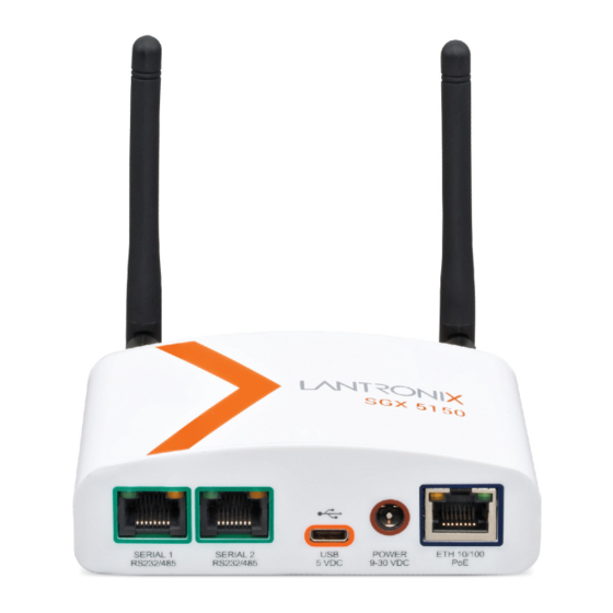
4. Data logger (normally installed in the data logger enclosure) − Note The data logger system should have the serial cable which connects the SGX 5150 serial port to the data logger serial port already installed. SGX 5150 Connections (Figure 1 - Front view of the Lantronix SGX 5150) (Figure 2 - Rear view of the Lantronix SGX 5150) Note - Serial 1 and Serial 2 are sometimes referred to as “Line 1”... - Page 3 (Table 1 - Note: ‘n’ can be any digit 0 to 9) − Note The SGX 5150 does include support for DHCP but it is NOT recommended to use this as IP addresses can be re-assigned which will require MultiLogger configuration to be updated.
- Page 4 Blue text indicates command responses from the SXG 5150. For brevity, not all SGX 5150 responses are shown. Connection is complete once WLAN and SIGNAL lights on the SGX 5150 turn on, this may take a few minutes. Using the Lantronix SGX 5150 Serial Device Server...
- Page 5 Confirm Connection The SGX 5150 should now be configured for your wireless network. This can be tested by opening a web browser and typing the SGX 5150 IP address into the address bar. When prompted for a username, enter "admin". The password, for devices manufactured after January 1, 2020, is the last 8 characters of the Device ID, or for older units use “PASS”.
- Page 6 Be sure to use the settings utilized with your infrastructure. The ports for the Serial Ports are as follows: ▪ Serial Port 1: 10001 (Serial Port 1 is Line 1 on the SGX 5150) ▪ Serial Port 2: 10002 (Serial Port 2 is Line 2 on the SGX 5150) ...
- Page 7 Press the Monitor button on the Logger toolbar to start the Monitor mode. This initiates a socket connection to the device and attempts to start the Monitor mode. If successful, the Datalogger Clock starts updating to indicate successful communication. (Figure 6) Using the Lantronix SGX 5150 Serial Device Server...
-
Page 8: Appendix A - Sgx 5150 Reset
Appendix A – SGX 5150 Reset To reset the SGX 5150 and restore the manufacturer default settings: Press the Reset button as shown in the figure below for 6 seconds. The SGX 5150 configuration automatically reboots as the button is released. -
Page 9: Appendix B - Troubleshooting Pc Wireless
Appendix B – Troubleshooting PC Wireless If your PC’s wireless adapter will not connect to the SGX 5150, then these steps may help resolve the lack of connectivity: 1. After the device connects, go to the PC’s Network and Internet settings. - Page 10 4. Select Use the following IP address and enter a Default gateway, Subnet mask and unique IP address for your network. (Example shown in Figure 11) (Figure 12) 5. Then click on OK. Using the Lantronix SGX 5150 Serial Device Server...
-
Page 11: Appendix C - Diagnostic Lights
Appendix C – Diagnostic Lights The lights on the front of the SGX 5150 can be used for basic network troubleshooting: WPS Status Blink Pattern WPS is enabled and on Short, continuous WPS has a profile error Long, long, long, short, short, 2 seconds off, continuous... -
Page 12: Appendix D - Gui Based Configuration Via Wi-Fi
1. Connect the SGX 5150 to a PC with a Web Browser. The following steps assume the SGX 5150 is new and has not been configured. (If the unit has been configured a wireless network, please see Appendix A for instructions to reset the device.) 2. - Page 13 7. On the Quick Setup status page in your browser, set the following options: ▪ DHCP Client OFF ▪ Enter the desired IP address for the SGX 5150 (example indicated) ▪ Enter the Default Gateway address (example indicated) ▪ IPv6 State Disabled ▪...
- Page 14 9. Select the Network tab on the top menu, expand Wireless Network and Link on the left side menu and select Configuration. In this window choose "Antenna 1" from the Antenna Diversity. (Figure 19) 10. At the bottom of the SGX 5150 Wireless Network page, click the Submit button. (Figure 20) Using the Lantronix SGX 5150 Serial Device Server...
- Page 15 Follow the matrix below for the proper setting for your system: Datalogger Baud Rate Setting CR2xx 9600 CR300/CR800/CR1000/CR6/ 115200 MLGPS/TM50 & TM30 Robots SlideMinder 38400 (Table 3) 12. Press Submit at the bottom of the page. (Figure 22) Using the Lantronix SGX 5150 Serial Device Server...
- Page 16 Wait 2 or 3 minutes for the device to reboot and access your chosen wireless network at the new IP address. Note - Most likely you will have to reconnect to your PC to the chosen network to connect to the SX 5150. Using the Lantronix SGX 5150 Serial Device Server...
-
Page 17: Appendix E - Gui Based Configuration Via Ethernet
Device Installer - a free program from Lantronix. This program is available at www.lantronix.com/support/downloads 1. Connect the Ethernet port of the SGX 5150 to a network adapter to a local PC. Make sure the adapter is set to DHCP (see Appendix B). -
Page 18: Appendix F - Switched Power Control For Campbell Dataloggers
Appendix F – Switched Power Control for Campbell Dataloggers Campbell Scientific dataloggers include programmable power outputs, such as Switch 12 (SW12), which can be used to control power to connected devices, such as the Lantronix SGX 5150. (Figure 28) SW12 provides a programmable output of 12 volts to the connected device and by doing so, the following can be achieved: •... - Page 19 5. Save the Program Configuration once the desired functionality is selected and return to the Device Configuration form. 6. To push the updated program to the datalogger, first verify the program, then Update Using the Lantronix SGX 5150 Serial Device Server...
- Page 20 1. Open the logger form for the datalogger and navigate to the Program tab. 2. SW12 power configuration is enabled by selecting an Output Device from the drop-down menu, highlighted in the figure below. a. For a CR300 select “Turn On Cell Modem” (Figure 31) Using the Lantronix SGX 5150 Serial Device Server...
- Page 21 For a CR6 select “Cycle Cell Modem Power (SW12-1)” or “Cycle Cell Model Power (SW12-2)” depending how the datalogger has been wired. (Figure 32) Using the Lantronix SGX 5150 Serial Device Server...
- Page 22 Note - It is important to leave the “,3” at the end of the first line of the gage file as it indicates the location of the code within the program. 5. Save the Gage File and build the program by pressing the button. Using the Lantronix SGX 5150 Serial Device Server...
- Page 23 In the code below PortSet(SW12,1) is used to turn on SW12 and PortSet (SW12,0) is used to turn off SW12. The if TIME_HHMM statement is checking whether the current time is between 12pm and 1pm. (Figure 34) Using the Lantronix SGX 5150 Serial Device Server...
- Page 24 3. Units is the parameter used to define the units of the previous two parameters. These units will be time and the following are accepted inputs. a. Msec (milliseconds) b. Sec (seconds) c. Min (minutes) d. Hr (hours) e. Day (days) Mon (months) (Figure 35) Using the Lantronix SGX 5150 Serial Device Server...
- Page 25 SGX-5150 is removed from the charge controller and connected into the CR300/CR6. Below are images of both the CR300 and CR6 dataloggers for reference. The connected device will be powered through the ports labeled as SW12 and G. (Figure 36) (Figure 37) Using the Lantronix SGX 5150 Serial Device Server...
- Page 26 Hint - These example uses a CH200 as the charge controller, however, this could also be a SunSaver. MCLOG The first figure depicts the wire configuration when the MCLOG is shipped, with both the SGX 5150 and the datalogger connecting to the charge controller.
- Page 27 MLDAQ The first figure depicts the wire configuration when the MLDAQ is shipped, with both the SGX 5150 and the datalogger connecting to the charge controller. (Figure 40) In the next figure, the wires previously connecting the SGX 5150 to the charge controller have been disconnected from the CH200 and reconnected directly to one of the SW12 ports of the CR6, sending power to the SGX 5150 through SW12.
Need help?
Do you have a question about the SGX 5150 and is the answer not in the manual?
Questions and answers