Planet IGS-10020MT User Manual
Industrial 8-port 10/100/1000t + 2 100/1000x sfp managed switch
Hide thumbs
Also See for IGS-10020MT:
- Command manual (433 pages) ,
- Quick installation manual (23 pages)

Subscribe to Our Youtube Channel
Related Manuals for Planet IGS-10020MT


Summary of Contents for Planet IGS-10020MT
- Page 1 User’s Manual of IGS-10020MT User’s Manual IGS-10020MT Industrial 8-Port 10/100/1000T + 2 100/1000X SFP Managed Switch...
-
Page 2: Fcc Warning
PLANET is a registered trademark of PLANET Technology Corp. All other trademarks belong to their respective owners. Disclaimer PLANET Technology does not warrant that the hardware will work properly in all environments and applications, and makes no warranty and representation, either implied or expressed, with respect to the quality, performance, merchantability, or fitness for a particular purpose. -
Page 3: Table Of Contents
User’s Manual of IGS-10020MT TABLE OF CONETNTS 1. INTRODUCTION........................20 1.1 Packet Contents ............................20 1.2 Product Description ...........................20 1.3 How to Use This Manual ..........................22 1.4 Product Features............................23 1.5 Product Specification ..........................26 2. INSTALLATION ........................28 2.1 Hardware Description ..........................28 2.1.1 Physical Dimension .............................28... - Page 4 User’s Manual of IGS-10020MT 4. WEB CONFIGURATION ...................... 49 4.1 Main Web Page ............................52 4.2 System.................................54 4.2.1 System Information..............................55 4.2.2 IP Configuration ..............................56 4.2.3 IPv6 Configuration ...............................57 4.2.4 Users Configuration .............................58 4.2.5 Privilege Levels ..............................61 4.2.6 NTP Configuration ...............................63 4.2.7 UPnP ...................................64 4.2.8 DHCP Relay ................................65...
- Page 5 User’s Manual of IGS-10020MT 4.4.3 Port Thermal Protection.............................101 4.4.4 Port Thermal Protection Status ..........................102 4.4.5 Port Statistics Detail............................103 4.4.6 SFP Information..............................105 4.4.7 Port Mirror................................106 4.5 Link Aggregation ............................108 4.5.1 Static Aggregation.............................. 111 4.5.2 LACP Configuration ............................113 4.5.3 LACP System Status ............................114 4.5.4 LACP Port Status...............................
- Page 6 User’s Manual of IGS-10020MT 4.7.9 Port Statistics..............................164 4.8 Multicast ..............................165 4.8.1 IGMP Snooping ..............................165 4.8.2 IGMP Snooping Configuration ...........................169 4.8.3 IGMP Snooping VLAN Configuration.........................170 4.8.4 IGMP Snooping Port Group Filtering .........................172 4.8.5 IGMP Snooping Status ............................173 4.8.6 IGMP Group Information............................174 4.8.7 IGMPv3 Information............................175...
- Page 7 User’s Manual of IGS-10020MT 4.9.16 Voice VLAN OUI Table.............................213 4.10 Access Control Lists..........................214 4.10.1 Access Control List Status ..........................214 4.10.2 Access Control List Configuration........................216 4.10.3 ACE Configuration ............................218 4.10.4 ACL Ports Configuration ..........................226 4.10.5 ACL Rate Limiter Configuration ........................228 4.11 Authentication............................230 4.11.1 Understanding IEEE 802.1X Port-Based Authentication..................231...
- Page 8 User’s Manual of IGS-10020MT 4.14.1 Link Layer Discovery Protocol .........................298 4.14.2 LLDP Configuration ............................298 4.14.3 LLDP-MED Configuration ..........................302 4.14.4 LLDP-MED Neighbor ............................308 4.14.5 Neighbor ................................311 4.14.6 Port Statistics..............................313 4.14.7 LLDP Neighbours EEE Information .........................315 4.15 Diagnostics .............................317 4.15.1 Ping .................................318 4.15.2 IPv6 Ping .................................319...
- Page 9 User’s Manual of IGS-10020MT System Log Server Mode ............................341 System Name..............................342 System Contact ..............................342 System Log Server Address ..........................343 System Location..............................343 System Log Level..............................344 System Timezone..............................345 System Log Lookup.............................345 System Reboot..............................346 System Restore Default............................346 System Load ...............................347 6.2 IP Command..............................347 IP Configuration..............................347...
- Page 10 User’s Manual of IGS-10020MT MAC Add ................................362 MAC Delete .................................363 MAC Lookup................................363 MAC Age Time ..............................364 MAC Learning ..............................364 MAC Dump................................365 MAC Statistics ..............................365 MAC Flush................................366 6.5 VLAN Configuration Command ......................367 VLAN Configuration.............................367 VLAV PVID ................................367 VLAN Frame Type ...............................368 VLAN Ingress Filter .............................369...
- Page 11 User’s Manual of IGS-10020MT Security Switch Privilege Level Current.......................383 Security Switch Auth Configuration ........................383 Security Switch Auth Method..........................384 Security Switch SSH Configuration ........................385 Security Switch SSH Mode..........................385 Security Switch HTTPs Configuration .........................386 Security Switch HTTPs Mode..........................386 Security Switch HTTPs Redirect .........................387 Security Switch Access Configuration .........................387...
- Page 12 User’s Manual of IGS-10020MT Security Switch SNMP User Add .........................404 Security Switch SNMP User Delete........................404 Security Switch SNMP User Changekey ......................405 Security Switch SNMP User Lookup ........................405 Security Switch SNMP Group Add........................406 Security Switch SNMP Group Delete ........................407 Security Switch SNMP Group Lookup .........................407 Security Switch SNMP View Add.........................408...
- Page 13 User’s Manual of IGS-10020MT Security Network ACL Add ..........................427 Security Network ACL Delete ..........................429 Security Network ACL Lookup ..........................429 Security Network ACL Clear ..........................430 Security Network ACL Status..........................430 Security Network DHCP Relay Configuration......................430 Security Network DHCP Relay Mode ........................431 Security Network DHCP Relay Server.........................432 Security Network DHCP Relay Information Mode ....................432...
- Page 14 User’s Manual of IGS-10020MT STP CName ................................449 STP BPDU Filter..............................449 STP BPDU Guard..............................450 STP Recovery ..............................450 STP Status ................................451 STP MSTI Priority..............................452 STP MSTI Map..............................452 STP MSTI Add..............................453 STP Port Configuration............................453 STP Port Mode ..............................454 STP Port Edge ..............................454 STP Port AutoEdge .............................455 STP Port P2P ..............................455...
- Page 15 User’s Manual of IGS-10020MT LLDP Hold ................................468 LLDP Delay .................................469 LLDP Reinit .................................469 LLDP Statistics ..............................470 LLDP Info ................................470 6.12 LLDPMED Command ..........................471 LLDPMED Configuration .............................471 LLDPMED Civic..............................472 LLDPMED ECS ..............................473 LLDPMED Policy Delete............................473 LLDPMED Policy Add............................473 LLDPMED Port Policy ............................474 LLDPMED Coordinates ............................475...
- Page 16 User’s Manual of IGS-10020MT QoS Port Scheduler Weight ..........................487 QoS Port QueueShaper Mode ..........................487 QoS Port QueueShaper Rate..........................488 QoS Port QueueShaper Excess..........................488 QoS Port Shaper Mode ............................489 QoS Port Shaper Rate ............................489 QoS Port TagRemarking Mode..........................490 QoS Port TagRemarking PCP ..........................490 QoS Port TagRemarking DEI..........................491...
- Page 17 User’s Manual of IGS-10020MT UPnP Configuration.............................505 UPnP Mode .................................505 UPnP TTL................................506 UPnP Advertising Duration ..........................506 6.20 MVR Command............................507 MVR Configuration ..............................507 MVR Group .................................508 MVR Status .................................508 MVR Mode ................................508 MVR Port Mode..............................509 MVR Multicast VLAN ............................509 MVR Port Type ..............................510 MVR Immediate Leave ............................510...
- Page 18 User’s Manual of IGS-10020MT IPMC Proxy .................................522 IPMC State ................................522 IPMC Querier ..............................523 IPMC Fastleave..............................523 IPMC Throttling ..............................524 IPMC Filtering..............................525 IPMC Router................................525 IPMC Status ................................526 IPMC Group ................................526 IPMC Version ..............................527 IPMC SSM................................527 IPMC Parameter RV............................528 IPMC Parameter QI.............................528 IPMC Parameter QRI ............................529 IPMC Parameter LLQI ............................529...
- Page 19 User’s Manual of IGS-10020MT SMTP Mailto1..............................537 SMTP Mailto2..............................537 SMTP Test ................................538 7. SWITCH OPERATION ....................... 539 7.1 Address Table ............................539 7.2 Learning ..............................539 7.3 Forwarding & Filtering ..........................539 7.4 Store-and-Forward ...........................539 7.5 Auto-Negotiation ............................540 8. TROUBLE SHOOTING...................... 541 APPENDEX A ........................543 A.1 Switch's Data RJ-45 Pin Assignments - 1000Mbps, 1000Base-T ............543...
-
Page 20: Introduction
1. INTRODUCTION The PLANET Industrial 8-Port 10/100/1000T + 2 100/1000X SFP Managed Switch –IGS-10020MT is all multiple ports Gigabit Ethernet Switched plus two SFP fiber optical connective ability and robust layer 2 features; the description of IGS-10020MT is shown as below:... - Page 21 Environmentally Hardened Design With IP30 aluminum industrial case protection, the IGS-10020MT provides a high level of immunity against electromagnetic interference and heavy electrical surges which are usually found on plant floors or in curb side traffic control cabinets. It also possesses an integrated power supply source with wide range of voltages (12 to 48V DC or 24V AC) for worldwide high availability applications requiring dual or backup power inputs.
-
Page 22: How To Use This Manual
User’s Manual of IGS-10020MT 1.3 How to Use This Manual This User Manual is structured as follows: Section 2, INSTALLATION The section explains the functions of the Industrial Managed Switch and how to physically install the Industrial Managed Switch. Section 3, SWITCH MANAGEMENT The section contains the information about the software function of the Industrial Managed Switch. -
Page 23: Product Features
User’s Manual of IGS-10020MT 1.4 Product Features Physical Port 8-Port 10/100/1000Base-T RJ-45 copper 2 100/1000Base-X mini-GBIC/SFP slots, SFP type auto detection Industrial Case / Installation IP30 Aluminum case protection DIN-Rail and Wall Mount Design ... - Page 24 User’s Manual of IGS-10020MT Traffic classification: IEEE 802.1p CoS IP TOS / DSCP / IP Precedence IP TCP/UDP port number Typical network application Strict priority and Weighted Round Robin (WRR) CoS policies Supports QoS and In/Out bandwidth control on each port ...
- Page 25 User’s Manual of IGS-10020MT NTP (Network Time Protocol) Link Layer Discovery Protocol (LLDP) Protocol Cable Diagnostic technology provides the mechanism to detect and report potential cabling issues Reset button for system reboot or reset to factory default...
-
Page 26: Product Specification
User’s Manual of IGS-10020MT 1.5 Product Specification Model Name IGS-10020MT Hardware Specification 8 10/ 100/1000Base-T RJ-45 Auto-MDI/MDI-X ports Copper Ports 2 1000Base-SX/LX/BX SFP interfaces (Port-9 and Port-10) SFP/mini-GBIC Slots Compatible with 100Base-FX SFP Store-and-Forward Switch Architecture 20Gbps / non-blocking Switch Fabric 14.8Mpps... - Page 27 User’s Manual of IGS-10020MT 8-level priority for switching - Port Number - 802.1p priority - 802.1Q VLAN tag - DSCP/TOS field in IP Packet IGMP (v1/v2/V3) Snooping, up to 255 multicast Groups IGMP Snooping IGMP Querier mode support MLD (v1/v2) Snooping, up to 255 multicast Groups...
-
Page 28: Installation
User’s Manual of IGS-10020MT 2. INSTALLATION 2.1 Hardware Description The Industrial Managed Switch provides three different running speeds – 10Mbps, 100Mbps and 1000Mbps in the same Switch and automatically distinguishes the speed of incoming connection. This section describes the hardware features of Industrial Managed Switch. For easier management and control of the Industrial Managed Switch, familiarize yourself with its display indicators, and ports. -
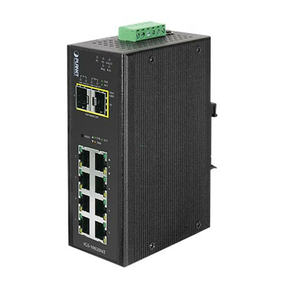
Page 29: Front Panel
User’s Manual of IGS-10020MT 2.1.2 Front Panel Figure 2-1 shows a front panel of Industrial Managed Switch. Figure 2-1: IGS-10020MT Switch Front Panel... - Page 30 User’s Manual of IGS-10020MT ■ Reset Button At the left of front panel, the reset button is designed for reboot the Industrial Managed Switch without turn off and on the power, also can reset the Industrial Managed Switch to factory default mode.
-
Page 31: Led Indicators
User’s Manual of IGS-10020MT 2.1.3 LED Indicators System Color Function Indicate the power 1 has power. Green ndicate the power 2 has power. Green ndicate the either power 1 or power 2 has no power. Fault Green Per 10/100/1000Base-T Port... -
Page 32: Switch Upper Panel
2.1.4 Switch Upper Panel The Upper Panel of the Industrial Managed Switch indicates a DC inlet power socket and consist one terminal block connector within 6-contacts. It accepts input power from 12 to 48V DC, also AC 24V. Figure 2-3: IGS-10020MT Upper Panel... -
Page 33: Install The Industrial Managed Switch
User’s Manual of IGS-10020MT 2.2 Install the Industrial Managed Switch This section describes how to install your Industrial Managed Switch and make connections to the Industrial Managed Switch. Please read the following topics and perform the procedures in the order being presented. To install your Industrial Managed Switch on a desktop or shelf, simply complete the following steps. -
Page 34: Din-Rail Mounting
User’s Manual of IGS-10020MT 2.2.2 DIN-Rail Mounting This section describes how to install the Industrial Managed Switch. There have two methods to install the Industrial Managed Switch. DIN-Rail Mounting and Wall Mount Plate Mounting. Please read the following topics and perform the procedures in the order being presented. - Page 35 User’s Manual of IGS-10020MT Step 3: Check the DIN-Rail is tightly on the track. Please refer to following procedures to remove the Industrial Managed Switch from the track. Step 4: Lightly press the button of DIN-Rail for remove it from the track.
-
Page 36: Wall Mount Plate Mounting
User’s Manual of IGS-10020MT 2.2.3 Wall Mount Plate Mounting To install the Industrial Managed Switch on the wall. Please follow the instructions below. Step 1: Remove the DIN-Rail from the Industrial Managed Switch. Use the screwdriver to loose the screws and remove the DIN-Rail. -
Page 37: Wiring The Power Inputs
User’s Manual of IGS-10020MT 2.3 Wiring the Power Inputs The 6-contacts terminal block connector on the top panel of Industrial Managed Switch is used for two DC redundant power inputs. Please follow the steps to insert the power wire. The PWR1 is 1(-) & 2(+) and PWR2 is 5(-) & 6(+) contact. -
Page 38: Cabling
User’s Manual of IGS-10020MT 1. The wire gauge for the terminal block should be in the range between 12 ~ 24 AWG. 2. Performing any of the procedures like inserting the wires or tighten the wire-clamp screws. Ensure the power is OFF to prevent to get an electric shock. -
Page 39: Installing The Sfp Transceiver
User’s Manual of IGS-10020MT 2.5.1 Installing the SFP Transceiver The sections describe how to insert an SFP transceiver into an SFP slot. The SFP transceivers are hot-pluggable and hot-swappable. You can plug-in and out the transceiver to/from any SFP port without having to power down the Industrial Managed Switch. - Page 40 User’s Manual of IGS-10020MT SFP-Port 1000Base-SX mini-GBIC module - 550m (-40~75℃) MGB-TSX SFP-Port 1000Base-LX mini-GBIC module - 10km (-40~75℃) MGB-TLX SFP-Port 1000Base-LX mini-GBIC module - 30km (-40~75℃) MGB-TL30 SFP-Port 1000Base-LX mini-GBIC module - 70km (-40~75℃) MGB-TL70 Fast Ethernet SFP Transceiver Modules...
-
Page 41: Remove The Module
User’s Manual of IGS-10020MT Make sure both side of the SFP transceiver are with the same media type or WDM pair, for example: 100Base-FX to 100Base-FX, 100Base-BX20-U to 100Base-BX20-D. Check the fiber-optic cable type match the SFP transceiver model. ... -
Page 42: Switch Management
User’s Manual of IGS-10020MT 3. SWITCH MANAGEMENT This chapter explains the methods that you can use to configure management access to the Industrial Managed Switch. It describes the types of management applications and the communication and management protocols that deliver data between your management device (workstation or personal computer) and the system. -
Page 43: Management Access Overview
User’s Manual of IGS-10020MT 3.2 Management Access Overview The Industrial Managed Switch gives you the flexibility to access and manage it using any or all of the following methods: Remote Telnet Interface Web browser Interface An external SNMP-based network management application The Remote Telnet and Web browser interface support are embedded in the Industrial Managed Switch software and are available for immediate use. -
Page 44: Remote Telnet
User’s Manual of IGS-10020MT 3.3 Remote Telnet The Remote Telnet is an IP-based command line user interface for performing system administration such as displaying statistics or changing option settings. Using this method, you can access the Industrial Managed Switch remote telnet interface from personal computer, or workstation in the same Ethernet environment. -
Page 45: Web Management
User’s Manual of IGS-10020MT 3.4 Web Management The Industrial Managed Switch offers management features that allow users to manage the Industrial Managed Switch from anywhere on the network through a standard browser such as Microsoft Internet Explorer. After you set up your IP address for the Industrial Managed Switch, you can access the Industrial Managed Switch’s Web interface applications directly in your... -
Page 46: Snmp-Based Network Management
User’s Manual of IGS-10020MT 3.5 SNMP-Based Network Management You can use an external SNMP-based application to configure and manage the Industrial Managed Switch, such as SNMPc Network Manager, HP Openview Network Node Management (NNM) or What’s Up Gold. This management method requires the SNMP agent on the Industrial Managed Switch and the SNMP Network Management Station to use the same community string. -
Page 47: Planet Smart Discovery Utility
User’s Manual of IGS-10020MT 3.6 PLANET Smart Discovery Utility For easily list the Industrial Managed Switch in your Ethernet environment, the Planet Smart Discovery Utility from user’s manual CD-ROM is an ideal solution. The following install instructions guiding you for run the Planet Smart Discovery Utility. - Page 48 User’s Manual of IGS-10020MT This utility show all necessary information from the devices, such as MAC Address, Device Name, firmware version, Device IP Subnet address, also can assign new password, IP Subnet address and description for the devices. After setup completed, press “Update Device”, “Update Multi” or “Update All” button to take affect. The meaning of the 3 buttons above are shown as below: ...
-
Page 49: Web Configuration
User’s Manual of IGS-10020MT 4. WEB CONFIGURATION This section introduces the configuration and functions of the Web-Based management. About Web-based Management The Industrial Managed Switch offers management features that allow users to manage the Industrial Managed Switch from anywhere on the network through a standard browser such as Microsoft Internet Explorer. - Page 50 User’s Manual of IGS-10020MT Logging on the Industrial Managed Switch Use Internet Explorer 7.0 or above Web browser. Enter the factory-default IP address to access the Web interface. The factory-default IP Address as following: http://192.168.0.100 When the following login screen appears, please enter the default username "admin" with password “admin” (or the username/password you have changed via console) to login the main screen of Industrial Managed Switch.
- Page 51 User’s Manual of IGS-10020MT Figure 4-1-3: Default Main Page Now, you can use the Web management interface to continue the switch management or manage the Industrial Managed Switch by Web interface. The Switch Menu on the left of the web page let you access all the commands and statistics the Managed Switch provides.
-
Page 52: Main Web Page
User’s Manual of IGS-10020MT 4.1 Main Web Page The Industrial Managed Switch provides a Web-based browser interface for configuring and managing it. This interface allows you to access the Industrial Managed Switch using the Web browser of your choice. This chapter describes how to use the Industrial Managed Switch’s Web browser interface to configure and manage it. - Page 53 User’s Manual of IGS-10020MT Main Menu Using the onboard web agent, you can define system parameters, manage and control the Industrial Managed Switch, and all its ports, or monitor network conditions. Via the Web-Management, the administrator can setup the Industrial Managed Switch by select the functions those listed in the Main Function.
-
Page 54: System
User’s Manual of IGS-10020MT 4.2 System Use the System menu items to display and configure basic administrative details of the Industrial Managed Switch. Under System the following topics are provided to configure and view the system information: This section has the following items: The switch system information is provided here. -
Page 55: System Information
User’s Manual of IGS-10020MT 4.2.1 System Information The System Info page provides information for the current device information. System Info page helps a switch administrator to identify the hardware MAC address, software version and system uptime. The screen in Figure 4-2-1 appears. -
Page 56: Ip Configuration
User’s Manual of IGS-10020MT 4.2.2 IP Configuration The IP Configuration includes the IP Address, Subnet Mask and Gateway. The Configured column is used to view or change the IP configuration. Fill up the IP Address, Subnet Mask and Gateway for the device. The screen in Figure 4-2-2 appears. -
Page 57: Ipv6 Configuration
User’s Manual of IGS-10020MT : Click to renew DHCP Client. This button is only available if DHCP Client is enabled. 4.2.3 IPv6 Configuration Configure the switch-managed IPv6 information on this page. The Configured column is used to view or change the IPv6 configuration. The Current column is used to show the active IPv6 configuration. -
Page 58: Users Configuration
User’s Manual of IGS-10020MT Buttons : Click to save changes. : Click to undo any changes made locally and revert to previously saved values. : Click to renew IPv6 Auto Configuration. This button is only available if IPv6 Auto Configuration is enabled. - Page 59 User’s Manual of IGS-10020MT Buttons : Click to add a new user. Add / Edit User This page configures a user – add, edit or delete user. Figure 4-2-5: Add / Edit User Configuration Page Screenshot The page includes the following fields:...
- Page 60 User’s Manual of IGS-10020MT : Delete the current user. This button is not available for new configurations (Add new user) Figure 4-2-6: User Configuration Page Screenshot After change the default password, if you forget the password. Please press the “Reset” button...
-
Page 61: Privilege Levels
User’s Manual of IGS-10020MT 4.2.5 Privilege Levels This page provides an overview of the privilege levels. After setup completed, please press “Save” button to take effect. Please login web interface with new user name and password, the screen in Figure 4-2-7 appears. - Page 62 User’s Manual of IGS-10020MT The page includes the following fields: Object Description Group Name The name identifying the privilege group. In most cases, a privilege level group consists of a single module (e.g. LACP, RSTP or QoS), but a few of them contains more than one.
-
Page 63: Ntp Configuration
User’s Manual of IGS-10020MT 4.2.6 NTP Configuration Configure NTP on this page. NTP is an acronym for Network Time Protocol, a network protocol for synchronizing the clocks of computer systems. NTP uses UDP (data grams) as transport layer. You can specify NTP Servers and set GMT Time zone. The NTP Configuration... -
Page 64: Upnp
User’s Manual of IGS-10020MT 4.2.7 UPnP Configure UPnP on this page. UPnP is an acronym for Universal Plug and Play. The goals of UPnP are to allow devices to connect seamlessly and to simplify the implementation of networks in the home (data sharing, communications, and entertainment) and in corporate environments for simplified installation of computer components. -
Page 65: Dhcp Relay
User’s Manual of IGS-10020MT Figure 4-2-10: UPnP Devices shows on Windows My Network Places 4.2.8 DHCP Relay Configure DHCP Relay on this page. DHCP Relay is used to forward and to transfer DHCP messages between the clients and the server when they are not on the same subnet domain. - Page 66 User’s Manual of IGS-10020MT Configuration screen in Figure 4-2-11 appears. Figure 4-2-11: DHCP Relay Configuration Page Screenshot The page includes the following fields: Object Description Relay Mode Indicates the DHCP relay mode operation. Possible modes are: Enabled: Enable DHCP relay mode operation. When enable DHCP relay mode operation, the agent forward and to transfer DHCP messages between the clients and the server when they are not on the same subnet domain.
-
Page 67: Dhcp Relay Statistics
User’s Manual of IGS-10020MT Buttons : Click to save changes. : Click to undo any changes made locally and revert to previously saved values. 4.2.9 DHCP Relay Statistics This page provides statistics for DHCP relay. The DHCP Relay Statistics screen in Figure 4-2-12 appears. - Page 68 User’s Manual of IGS-10020MT Receive form Client The number of received packets from server. Receive Agent Option The number of received packets with relay agent information option. Replace Agent Option The number of packets which were replaced with relay agent information option.
-
Page 69: Cpu Load
User’s Manual of IGS-10020MT 4.2.10 CPU Load This page displays the CPU load, using a SVG graph. The load is measured as averaged over the last 100ms, 1sec and 10 seconds intervals. The last 120 samles are graphed, and the last numbers are displayed as text as well. -
Page 70: System Log
User’s Manual of IGS-10020MT 4.2.11 System Log The switch system log information is provided here. The System Log screen in Figure 4-2-14 appears. Figure 4-2-14: System Log Page Screenshot The page includes the following fields: Object Description ID The ID (>= 1) of the system log entry. -
Page 71: Detailed Log
User’s Manual of IGS-10020MT 4.2.12 Detailed Log The switch system detailed log information is provided here. The Detailed Log screen in Figure 4-2-15 appears. Figure 4-2-15: Detailed Log Page Screenshot The page includes the following fields: Object Description ID The ID (>= 1) of the system log entry. -
Page 72: Remote Syslog
User’s Manual of IGS-10020MT 4.2.13 Remote Syslog Configure remote syslog on this page. The Remote Syslog screen in Figure 4-2-16 appears. Figure 4-2-16: Remote Syslog Page Screenshot The page includes the following fields: Object Description Server Mode Indicates the server mode operation. When the mode operation is enabled, the syslog message will send out to syslog server. -
Page 73: Smtp Configuration
User’s Manual of IGS-10020MT 4.2.14 SMTP Configuration Configure SMTP Configuration on this page. The SMTP Configuration screen in Figure 4-2-17 appears. Figure 4-2-17: SMTP Configuration Page Screenshot The page includes the following fields: Object Description SMTP Mode Enabled It is for you to enable SMTP mode function. This mode offers you to configure... - Page 74 User’s Manual of IGS-10020MT Buttons : Click to test SMTP server address. : Click to save changes. : Click to undo any changes made locally and revert to previously saved values.
-
Page 75: Eee Power Reduction
User’s Manual of IGS-10020MT 4.2.15 EEE Power Reduction This page allows the user to configure the current EEE port settings. EEE is a power saving option that reduces the power usage when there is low or no traffic utilization. EEE works by powering down circuits when there is no traffic. When a port gets data to be transmitted all circuits are powered up. - Page 76 User’s Manual of IGS-10020MT The page includes the following fields: Object Description Port The switch port number of the logical EEE port, means to select all ports of Industrial Managed Switch. EEE Enable Controls whether EEE is enabled for this switch port.
-
Page 77: Web Firmware Upgrade
User’s Manual of IGS-10020MT 4.2.16 Web Firmware Upgrade This page facilitates an update of the firmware controlling the Industrial Managed Switch. The Web Firmware Upgrade screen Figure 4-2-19 appears. Figure 4-2-19: Web Firmware Upgrade Page Screenshot To open Firmware Upgrade screen perform the folling: Click System ->... -
Page 78: Tftp Firmware Upgrade
User’s Manual of IGS-10020MT 4.2.17 TFTP Firmware Upgrade The Firmware Upgrade page provides the functions to allow a user to update the Industrial Managed Switch firmware from the TFTP server in the network. Before updating, make sure you have your TFTP server ready and the firmware image is on the TFTP server. -
Page 79: Configuration Backup
User’s Manual of IGS-10020MT 4.2.18 Configuration Backup This function allows backup and reload the current configuration of the Industrial Managed Switch to the local management station. The Configuration Backup screen in Figure 4-2-22 appears. Figure 4-2-22: Configuration Save Page Screenshot You can save/view or load the switch configuration. - Page 80 User’s Manual of IGS-10020MT Figure 4-2-23: File Download Screen Chose the file save path in management workstation. Figure 4-2-24: File Save Screen...
-
Page 81: Configuration Upload
User’s Manual of IGS-10020MT 4.2.19 Configuration Upload This function allows backup and reload the current configuration of the Industrial Managed Switch to the local management station. The Configuration Upload screen in Figure 4-2-25 appears. Figure 4-2-25: Configuration Upload Page Screenshot ... -
Page 82: Image Select
User’s Manual of IGS-10020MT 4.2.20 Image Select This function provides dual image deposit in the Industrial Managed Switch, user can select any one of the image as Active image of Industrial Managed Switch. The Image Select screen in Figure 4-2-27 appears. - Page 83 User’s Manual of IGS-10020MT Figure 4-2-30: Image Select Page Screenshot Figure 4-2-31: Image Select Page Screenshot After the system reboot, you can use the Alternate Image of Industrial Managed Switch.
-
Page 84: Factory Default
User’s Manual of IGS-10020MT 4.2.21 Factory Default You can reset the configuration of the stack switch on this page. Only the IP configuration is retained. The new configuration is available immediately, which means that no restart is necessary. The Factory Default screen in Figure 4-2-32 appears. -
Page 85: System Reboot
User’s Manual of IGS-10020MT 4.2.22 System Reboot The Reboot page enables the device to be rebooted from a remote location. Once the Reboot button is pressed, user will re-access the WEB interface about 60 seconds later, the System Reboot screen in Figure 4-2-34 appears. -
Page 86: Simple Network Management Protocol
User’s Manual of IGS-10020MT 4.3 Simple Network Management Protocol 4.3.1 SNMP Overview The Simple Network Management Protocol (SNMP) is an application layer protocol that facilitates the exchange of management information between network devices. It is part of the Transmission Control Protocol/Internet Protocol (TCP/IP) protocol suite. -
Page 87: Snmp System Configuration
User’s Manual of IGS-10020MT Configure SNMPv3 groups table on this page. SNMPv3 Groups Configure SNMPv3 views table on this page. SNMPv3 Views Configure SNMPv3 accesses table on this page. SNMPv3 Accesses 4.3.2 SNMP System Configuration Configure SNMP on this page. The SNMP System Configuration screen in Figure 4-3-1 appears. - Page 88 User’s Manual of IGS-10020MT The allowed string length is 0 to 255, and the allowed content is the ASCII characters from 33 to 126. The field is applicable only when SNMP version is SNMPv1 or SNMPv2c. If SNMP version is SNMPv3, the community string will be associated with SNMPv3 communities table.
- Page 89 User’s Manual of IGS-10020MT separating each field (:). For example, 'fe80::215:c5ff:fe03:4dc7'. The symbol '::' is a special syntax that can be used as a shorthand way of representing multiple 16-bit groups of contiguous zeros; but it can appear only once. It can also represent a legally valid IPv4 address.
-
Page 90: Snmp System Information
User’s Manual of IGS-10020MT 4.3.3 SNMP System Information The switch system information is provided here. The SNMP System Information screen in Figure 4-3-2 appears. Figure 4-3-2: System Information Configuration Page Screenshot The page includes the following fields: Object Description ... -
Page 91: Snmpv3 Configuration
User’s Manual of IGS-10020MT 4.3.4 SNMPv3 Configuration 4.3.4.1 SNMPv3 Communities Configure SNMPv3 communities table on this page. The entry index key is Community. The SNMPv3 Communities screen in Figure 4-3-3 appears. Figure 4-3-3: SNMPv3 Communities Configuration Page Screenshot The page includes the following fields:... -
Page 92: Snmpv3 Users
User’s Manual of IGS-10020MT 4.3.4.2 SNMPv3 Users Configure SNMPv3 users table on this page. The entry index keys are Engine ID and User Name. The SNMPv3 Users screen in Figure 4-3-4 appears. Figure 4-3-4: SNMPv3 Users Configuration Page Screenshot The page includes the following fields:... - Page 93 User’s Manual of IGS-10020MT SHA: An optional flag to indicate that this user using SHA authentication protocol. The value of security level cannot be modified if entry already exists. That means must first ensure that the value is set correctly.
-
Page 94: Snmpv3 Groups
User’s Manual of IGS-10020MT 4.3.4.3 SNMPv3 Groups Configure SNMPv3 groups table on this page. The entry index keys are Security Model and Security Name. The SNMPv3 Groups screen in Figure 4-3-5 appears. Figure 4-3-5: SNMPv3 Groups Configuration Page Screenshot The page includes the following fields:... -
Page 95: Snmpv3 Views
User’s Manual of IGS-10020MT 4.3.4.4 SNMPv3 Views Configure SNMPv3 views table on this page. The entry index keys are View Name and OID Subtree. The SNMPv3 Views screen in Figure 4-3-6 appears. Figure 4-3-6: SNMPv3 Views Configuration Page Screenshot The page includes the following fields:... -
Page 96: Snmpv3 Access
User’s Manual of IGS-10020MT 4.3.4.5 SNMPv3 Access Configure SNMPv3 accesses table on this page. The entry index keys are Group Name, Security Model and Security Level. The SNMPv3 Access screen in Figure 4-3-7 appears. Figure 4-3-7: SNMPv3 Accesses Configuration Page Screenshot... - Page 97 User’s Manual of IGS-10020MT Buttons : Click to add a new access entry. : Click to save changes. : Click to undo any changes made locally and revert to previously saved values.
-
Page 98: Port Management
User’s Manual of IGS-10020MT 4.4 Port Management Use the Port Menu to display or configure the Managed Switch's ports. This section has the following items: Configures port connection settings Port Configuration Lists Ethernet and RMON port statistics Port Statistics Overview ... - Page 99 User’s Manual of IGS-10020MT Select any available link speed for the given switch port. Draw the menu bar to Configured Link Speed select the mode. All- Setup whole ports with the same setting. Auto Copper - Setup Auto negotiation.
-
Page 100: Port Statistics Overview
User’s Manual of IGS-10020MT : Click to refresh the page. Any changes made locally will be undone. 4.4.2 Port Statistics Overview This page provides an ov erview of general traffic statistics for all switch ports. The Port Statistics Overview screen in... -
Page 101: Port Thermal Protection
User’s Manual of IGS-10020MT 4.4.3 Port Thermal Protection This page allows the user to inspect and configure the current setting for controlling thermal protection. Thermal protection is used to protect the chip from getting overheated. When the temperature exceeds the configured thermal protection temperature, ports will be turned off in order to decrease the power consumption. -
Page 102: Port Thermal Protection Status
User’s Manual of IGS-10020MT 4.4.4 Port Thermal Protection Status This page allows the user to inspect status information related to thermal protection. The Port Thermal Protection Status screen Figure 4-4-4 appears. Figure 4-4-4: Thermal Protection Status Page Screenshot The displayed counters are:... -
Page 103: Port Statistics Detail
User’s Manual of IGS-10020MT 4.4.5 Port Statistics Detail This page provides detailed traffic statistics for a specific switch port. Use the port select box to select which switch port details to display. The selected port belong to the currently selected stack unit, as reflected by the page header. The displayed counters are the totals for receive and transmit, the size counters for receive and transmit, and the error counters for receive and transmit. - Page 104 User’s Manual of IGS-10020MT Receive and Transmit Size Counters The number of received and transmitted (good and bad) packets split into categories based on their respective frame sizes. Receive and Transmit Queue Counters The number of received and transmitted packets per input and output queue.
-
Page 105: Sfp Information
User’s Manual of IGS-10020MT 4.4.6 SFP Information You can check the physical or operational status of an SFP module via the SFP Module Information page. This page shows the operational status, such as the transceiver type, speed, and wavelength and supports distance of SFP module on a specific interface. -
Page 106: Port Mirror
User’s Manual of IGS-10020MT 4.4.7 Port Mirror Configure port Mirroring on this page. This function provide to monitoring network traffic that forwards a copy of each incoming or outgoing packet from one port of a network Switch to another port where the packet can be studied. It enables the manager to keep close track of switch performance and alter it if necessary. - Page 107 User’s Manual of IGS-10020MT Mirror Port Configuration The Port Mirror screen in Figure 4-4-8 appears. Figure 4-4-8: Mirror Configuration Page Screenshot The page includes the following fields: Object Description Port to mirror on Port to mirror also known as the mirror port. Frames from ports that have either source (rx) or destination (tx) mirroring enabled are mirrored on this port.
-
Page 108: Link Aggregation
User’s Manual of IGS-10020MT Buttons : Click to save changes. : Click to undo any changes made locally and revert to previously saved values. 4.5 Link Aggregation Port Aggregation optimizes port usage by linking a group of ports together to form a single Link Aggregated Groups (LAGs). Port Aggregation multiplies the bandwidth between the devices, increases port flexibility, and provides link redundancy. - Page 109 User’s Manual of IGS-10020MT Figure 4-5-1: Link Aggregation Topology The Link Aggregation Control Protocol (LACP) provides a standardized means for exchanging information between Partner Systems that require high speed redundant links. Link aggregation lets you group up to eight consecutive ports into a single dedicated connection.
- Page 110 User’s Manual of IGS-10020MT It allows a maximum of 10 ports to be aggregated at the same time. The Managed Switch support Gigabit Ethernet ports (up to 5 groups). If the group is defined as a LACP static link aggregationing group, then any extra ports selected are placed in a standby mode for redundancy if one of the other ports fails.
-
Page 111: Static Aggregation
User’s Manual of IGS-10020MT 4.5.1 Static Aggregation This page is used to configure the Aggregation hash mode and the aggregation group. The aggregation hash mode settings are global, whereas the aggregation group relate to the currently selected stack unit, as reflected by the page header. - Page 112 User’s Manual of IGS-10020MT Static Aggregation Group Configuration The Aggregation Group Configuration screen in Figure 4-5-3 appears. Figure 4-5-3: Aggregation Group Configuration Page Screenshot The page includes the following fields: .Object Description Indicates the group ID for the settings contained in the same row. Group ID Group ID "Normal"...
-
Page 113: Lacp Configuration
User’s Manual of IGS-10020MT 4.5.2 LACP Configuration Link Aggregation Control Protocol (LACP) - LACP LAG negotiate Aggregated Port links with other LACP ports located on a different device. LACP allows switches connected to each other to discover automatically whether any ports are member of the same LAG. -
Page 114: Lacp System Status
User’s Manual of IGS-10020MT each second, while Passive will wait for a LACP packet from a partner (speak if spoken to). Buttons : Click to save changes. : Click to undo any changes made locally and revert to previously saved values. -
Page 115: Lacp Port Status
User’s Manual of IGS-10020MT 4.5.4 LACP Port Status This page provides a status overview for LACP status for all ports. The LACP Port Status screen in Figure 4-5-6 appears. Figure 4-5-6: LACP Status Page Screenshot The page includes the following fields:... -
Page 116: Lacp Port Statistics
User’s Manual of IGS-10020MT 4.5.5 LACP Port Statistics This page provides an overview for LACP statistics for all ports. The LACP Port Statistics screen in Figure 4-5-7 appears. Figure 4-5-7: LACP Statistics Page Screenshot The page includes the following fields:... -
Page 117: Vlan
User’s Manual of IGS-10020MT 4.6 VLAN 4.6.1 VLAN Overview A Virtual Local Area Network (VLAN) is a network topology configured according to a logical scheme rather than the physical layout. VLAN can be used to combine any collection of LAN segments into an autonomous user group that appears as a single LAN. -
Page 118: Ieee 802.1Q Vlan
User’s Manual of IGS-10020MT 4.6.2 IEEE 802.1Q VLAN In large networks, routers are used to isolate broadcast traffic for each subnet into separate domains. This Managed Switch provides a similar service at Layer 2 by using VLANs to organize any group of network nodes into separate broadcast domains. - Page 119 User’s Manual of IGS-10020MT Untagging - The act of stripping 802.1Q VLAN information out of the packet header. ■ 802.1Q VLAN Tags The figure below shows the 802.1Q VLAN tag. There are four additional octets inserted after the source MAC address. Their presence is indicated by a value of 0x8100 in the Ether Type field.
- Page 120 User’s Manual of IGS-10020MT ■ Port VLAN ID Packets that are tagged (are carrying the 802.1Q VID information) can be transmitted from one 802.1Q compliant network device to another with the VLAN information intact. This allows 802.1Q VLAN to span network devices (and indeed, the entire network –...
-
Page 121: Vlan Basic Information
User’s Manual of IGS-10020MT ■ VLAN Classification When the switch receives a frame, it classifies the frame in one of two ways. If the frame is untagged, the switch assigns the frame to an associated VLAN (based on the default VLAN ID of the receiving port). But if the frame is tagged, the switch uses the tagged VLAN ID to identify the port broadcast domain of the frame. -
Page 122: Vlan Port Configuration
User’s Manual of IGS-10020MT Configurable PVID Indicates whether or not configurable PVID tagging is implemented. Tagging 4.6.4 VLAN Port Configuration This page is used for configuring the Managed Switch port VLAN. The VLAN per Port Configuration page contains fields for managing ports that are part of a VLAN. - Page 123 User’s Manual of IGS-10020MT through the infrastructure might be mixed. Assigning a unique range of VLAN IDs to each customer would restrict customer configurations, require intensive processing of VLAN mapping tables, and could easily exceed the maximum VLAN limit of 4095.
- Page 124 User’s Manual of IGS-10020MT VLAN Port Configuration The VLAN Port Configuration screen in Figure 4-6-2 appears. Figure 4-6-2 : VLAN Port Configuration Page Screenshot The page includes the following fields: Object Description This is the logical port number for this row.
- Page 125 User’s Manual of IGS-10020MT Q-in-Q Mode Sets the Managed Switch to QinQ mode, and allows the QinQ tunnel port to be configured. The default is for the Managed Switch to function in Disable mode. - Disable: The port operates in its normal VLAN mode. (This is the default.) - MAN Port: Configures IEEE 802.1Q tunneling (QinQ) for an uplink port to...
-
Page 126: Vlan Membership
User’s Manual of IGS-10020MT 4.6.5 VLAN Membership Adding Static Members to VLANs (VLAN Index) Use the VLAN Static Table to configure port members for the selected VLAN index. The VLAN membership configuration for the selected stack switch / unit switch can be monitored and modified here. Up to 255 VLANs are supported. This page allows for adding and deleting VLANs as well as adding and deleting port members of each VLAN. -
Page 127: Vlan Membership Status
User’s Manual of IGS-10020MT A VLAN without any port members on any stack unit will be deleted when you click "Save". The button can be used to undo the addition of new VLANs. Buttons : Click to add new VLAN. - Page 128 User’s Manual of IGS-10020MT for all the VLAN Users, and this is the default. VLAN membership allows the frames Classified to the VLAN ID to be forwarded to the respective VLAN member ports. A VLAN User is a module that uses services of the VLAN management...
-
Page 129: Vlan Port Status
User’s Manual of IGS-10020MT 4.6.7 VLAN Port Status This page provides VLAN Port Staus. The VLAN Port Status screen in Figure 4-6-5 appears. Figure 4-6-5: VLAN Port Status for Static User Page Screenshot The page includes the following fields: Object Description ... -
Page 130: Private Vlan
User’s Manual of IGS-10020MT Direct conflict between user modules. A VLAN User is a module that uses services of the VLAN management VLAN User functionality to configure VLAN memberships and VLAN port configuration such as PVID, UVID. Currently we support following VLAN : - CLI/Web/SNMP : This are reffered as static. - Page 131 User’s Manual of IGS-10020MT Figure 4-6-6: Private VLAN Membership Configuration Page Screenshot The page includes the following fields: Object Description Delete To delete a private VLAN entry, check this box. The entry will be deleted during the next save.
-
Page 132: Port Isolation
User’s Manual of IGS-10020MT 4.6.9 Port Isolation Overview When a VLAN is configured to be a private VLAN, communication between ports within that VLAN can be prevented. Two application examples are provided in this section: Customers connected to an ISP can be members of the same VLAN, but they are not allowed to communicate with each other within that VLAN. -
Page 133: Vlan Setting Example
User’s Manual of IGS-10020MT The configuration of promiscuous and isolated ports applies to all private VLANs. When traffic comes in on a promiscuous port in a private VLAN, the VLAN mask from the VLAN table is applied. When traffic comes in on an isolated port, the private VLAN mask is applied in addition to the VLAN mask from the VLAN table. -
Page 134: Two Separate 802.1Q Vlan
User’s Manual of IGS-10020MT 4.6.10.1 Two separate 802.1Q VLAN The diagram shows how the Industrial Managed Switch handle Tagged and Untagged traffic flow for two VLANs. VLAN Group 2 and VLAN Group 3 are separated VLAN. Each VLAN isolate network traffic so only members of the VLAN receive traffic from the same VLAN members. - Page 135 User’s Manual of IGS-10020MT Tagged packet entering VLAN 2 While [PC-3] transmit a tagged packet with VLAN Tag=2 enters Port-3, [PC-1] and [PC-2] will received the packet through Port-1 and Port-2. While the packet leaves Port-1 and Port-2, it will be stripped away it tag becoming an untagged packet.
- Page 136 User’s Manual of IGS-10020MT It’s import to remove the VLAN members from VLAN 1 configuration. Or the ports would become overlap setting. ( About the overlapped VLAN configuration, see next VLAN configure sample) Assign PVID for each port: Port-1,Port-2 and Port-3 : PVID=2...
-
Page 137: Vlan Trunking Between Two 802.1Q Aware Switch
User’s Manual of IGS-10020MT 4.6.10.2 VLAN Trunking between two 802.1Q aware Switch The most cases are used for “Uplink” to other switches. VLANs are separated at different switches, but they need to access with other switches within the same VLAN group. The screen in Figure 4-6-11 appears. - Page 138 User’s Manual of IGS-10020MT Assign the VLAN Trunk Port to be the member of each VLAN – which wants to be aggregated. At this sample, add Port-8 to be VLAN 2 and VLAN 3 member port. The screen in Figure 4-6-12 appears.
-
Page 139: Port Isolate
User’s Manual of IGS-10020MT 4.6.10.3 Port Isolate The diagram shows how the Managed Switch handles isolate and promiscuous ports, and the each PCs are not able to access each other PCs of each isolate port. But they all need to access with the same server/AP/Printer. The screen in Figure 4-6-14 appears. -
Page 140: Mac-Based Vlan
User’s Manual of IGS-10020MT 4.6.11 MAC-based VLAN The MAC-based VLAN enties can be configured here. This page allows for adding and deleting MAC-based VLAN entries and assigning the entries to different ports. This page shows only static entries. The MAC-based VLAN screen in Figure 4-6-17 appears. -
Page 141: Mac-Based Vlan Status
User’s Manual of IGS-10020MT 4.6.12 MAC-based VLAN Status This page shows MAC-based VLAN entries configured by various MAC-based VLAN users. The MAC-based VLAN Status screen in Figure 4-6-18 appears. Figure 4-6-18: MAC-based VLAN Membership Configuration for User Static Page Screenshot... -
Page 142: Ip Subnet-Based Vlan
User’s Manual of IGS-10020MT 4.6.13 IP Subnet-based VLAN This page allows for adding, updating and deleting IP subnet-based VLAN entries and assigning the entries to different ports. The IP subnet-based VLAN screen in Figure 4-6-19 appears. Figure 4-6-19: IP subnet-based VLAN Page Screenshot... -
Page 143: Protocol-Based Vlan
User’s Manual of IGS-10020MT 4.6.14 Protocol-based VLAN This page allows you to add new protocols to Group Name (unique for each Group) mapping entries as well as allow you to see and delete already mapped entries for the switch. The Protocol-based VLAN screen in Figure 4-6-20 appears. - Page 144 User’s Manual of IGS-10020MT a.OUI: OUI (Organizationally Unique Identifier) is value in format of xx-xx-xx where each pair (xx) in string is a hexadecimal value ranges from 0x00-0xff. b. PID: If the OUI is hexadecimal 000000, the protocol ID is the Ethernet type (EtherType) field value for the protocol running on top of SNAP;...
-
Page 145: Protocol-Based Vlan Mambership
User’s Manual of IGS-10020MT 4.6.15 Protocol-based VLAN Mambership This page allows you to map a already configured Group Name to a VLAN for the switch. The Group Name to VLAN Mapping Table screen in Figure 4-6-21 appears. Figure 4-6-21: Group Name to VLAN Mapping Table Page Screenshot... -
Page 146: Spanning Tree Protocol
User’s Manual of IGS-10020MT 4.7 Spanning Tree Protocol 4.7.1 Theory The Spanning Tree protocol can be used to detect and disable network loops, and to provide backup links between switches, bridges or routers. This allows the switch to interact with other bridging devices in your network to ensure that only one route exists between any two stations on the network, and provide backup links which automatically take over when a primary link goes down. - Page 147 User’s Manual of IGS-10020MT The switch sends BPDUs to communicate and construct the spanning-tree topology. All switches connected to the LAN on which the packet is transmitted will receive the BPDU. BPDUs are not directly forwarded by the switch, but the receiving switch uses the information in the frame to calculate a BPDU, and, if the topology changes, initiates a BPDU transmission.
- Page 148 User’s Manual of IGS-10020MT Figure 4-7-1: STP Port State Transitions You can modify each port state by using management software. When you enable STP, every port on every switch in the network goes through the blocking state and then transitions through the states of listening and learning at power up. If properly configured, each port stabilizes to the forwarding or blocking state.
- Page 149 User’s Manual of IGS-10020MT Parameter Description Default Value A combination of the User-set priority and 32768 + MAC Bridge Identifier(Not user the switch’s MAC address. configurable The Bridge Identifier consists of two parts: except by setting priority a 16-bit priority and a 48-bit Ethernet MAC...
- Page 150 User’s Manual of IGS-10020MT User-Changeable STA Parameters The Switch’s factory default setting should cover the majority of installations. However, it is advisable to keep the default settings as set at the factory; unless, it is absolutely necessary. The user changeable parameters in the Switch are as follows: Priority –...
- Page 151 User’s Manual of IGS-10020MT Figure 4-7-2: Before Applying the STA Rules In this example, only the default STP values are used. Figure 4-7-3: After Applying the STA Rules...
-
Page 152: Stp System Configuration
User’s Manual of IGS-10020MT The switch with the lowest Bridge ID (switch C) was elected the root bridge, and the ports were selected to give a high port cost between switches B and C. The two (optional) Gigabit ports (default port cost = 20,000) on switch A are connected to one (optional) Gigabit port on both switch B and C. - Page 153 User’s Manual of IGS-10020MT The page includes the following fields: Basic Settings Object Description The STP protocol version setting. Valid values are STP, RSTP and MSTP. Protocol Version Bridge Priority Controls the bridge priority. Lower numeric values have better priority. The bridge priority plus the MSTI instance number, concatenated with the 6-byte MAC address of the switch forms a Bridge Identifier.
-
Page 154: Bridge Status
User’s Manual of IGS-10020MT re-enabled for normal STP operation. The condition is also cleared by a system reboot. The time that has to pass before a port in the error-disabled state can be Port Error Recovery enabled. Valid values are between 30 and 86400 seconds (24 hours). -
Page 155: Cist Port Configuration
User’s Manual of IGS-10020MT Buttons Auto-refresh : Check this box to refresh the page automatically. Automatic refresh occurs every 3 seconds. : Click to refresh the page immediate 4.7.4 CIST Port Configuration This page allows the user to inspect the current STP CIST port configurations, and possibly change them as well. The CIST Port... - Page 156 User’s Manual of IGS-10020MT Controls the port priority. This can be used to control priority of ports having Priority identical port cost. (See above). Default: 128 Range: 0-240, in steps of 16 All means all ports will have one specific setting.
- Page 157 User’s Manual of IGS-10020MT Buttons : Click to save changes. : Click to undo any changes made locally and revert to previously saved values. By default, the system automatically detects the speed and duplex mode used on each port, and configures the path cost according to the values shown below.
-
Page 158: Msti Priorities
User’s Manual of IGS-10020MT 4.7.5 MSTI Priorities This page allows the user to inspect the current STP MSTI bridge instance priority configurations, and possibly change them as well. The MSTI Priority screen in Figure 4-7-7 appears. Figure 4-7-7: MSTI Priority Page Screenshot... -
Page 159: Msti Configuration
User’s Manual of IGS-10020MT 4.7.6 MSTI Configuration This page allows the user to inspect the current STP MSTI bridge instance priority configurations, and possibly change them as well. The MSTI Configuration screen in Figure 4-7-8 appears. Figure 4-7-8: MSTI Configuration Page Screenshot... - Page 160 User’s Manual of IGS-10020MT The page includes the following fields: Configuration Identification Object Description Configuration Name The name identifiying the VLAN to MSTI mapping. Bridges must share the name and revision (see below), as well as the VLAN-to-MSTI mapping configuration in order to share spanning trees for MSTI's.
-
Page 161: Msti Ports Configuration
User’s Manual of IGS-10020MT 4.7.7 MSTI Ports Configuration This page allows the user to inspect the current STP MSTI port configurations, and possibly change them as well. A MSTI port is a virtual port, which is instantiated separately for each active CIST (physical) port for each MSTI instance configured and applicable for the port. - Page 162 User’s Manual of IGS-10020MT Figure 4-7-10: MST1 MSTI Port Configuration Page Screenshot The page includes the following fields: MSTx MSTI Port Configuration Object Description Port The switch port number of the corresponding STP CIST (and MSTI) port. Path Cost The Configuration All with available values will assign to whole items.
-
Page 163: Port Status
User’s Manual of IGS-10020MT Buttons : Click to set MSTx configuration : Click to save changes. : Click to undo any changes made locally and revert to previously saved values. 4.7.8 Port Status This page displays the STP CIST port status for port physical ports in the currently selected switch. -
Page 164: Port Statistics
User’s Manual of IGS-10020MT Forwarding Non-STP Uptime The time since the bridge port was last initialized. Buttons Auto-refresh : Check this box to refresh the page automatically. Automatic refresh occurs every 3 seconds. : Click to refresh the page immediate 4.7.9 Port Statistics... -
Page 165: Multicast
User’s Manual of IGS-10020MT 4.8 Multicast 4.8.1 IGMP Snooping The Internet Group Management Protocol (IGMP) lets host and routers share information about multicast groups memberships. IGMP snooping is a switch feature that monitors the exchange of IGMP messages and copies them to the CPU for feature processing. - Page 166 User’s Manual of IGS-10020MT Figure 4-8-2: Multicast Flooding Figure 4-8-3: IGMP Snooping Multicast Stream Control...
- Page 167 User’s Manual of IGS-10020MT IGMP Versions 1 and 2 Multicast groups allow members to join or leave at any time. IGMP provides the method for members and multicast routers to communicate when joining or leaving a multicast group. IGMP version 1 is defined in RFC 1112. It has a fixed packet size and no optional data.
- Page 168 User’s Manual of IGS-10020MT message, and query messages that are specific to a given group. The states a computer will go through to join or to leave a multicast group are shown below: Figure 4-8-4: IGMP State Transitions IGMP Querier –...
-
Page 169: Igmp Snooping Configuration
User’s Manual of IGS-10020MT 4.8.2 IGMP Snooping Configuration This page provides IGMP Snooping related configuration. The IGMP Snooping Configuration screen in Figure 4-8-5 appears. Figure 4-8-5: IGMP Snooping Configuration Page Screenshot The page includes the following fields: Object Description ... -
Page 170: Igmp Snooping Vlan Configuration
User’s Manual of IGS-10020MT If an aggregation member port is selected as a router port, the whole aggregation will act as a router port. All means all ports will have one specific setting. Fast Leave Enable the fast leave on the port. - Page 171 User’s Manual of IGS-10020MT RV Robustness Variable. The Robustness Variable allows tuning for the expected packet loss on a network. The allowed range is 1 to 255, default robustness variable value is 2. QI Query Interval. The Query Interval is the interval between General Queries sent by the Querier.
-
Page 172: Igmp Snooping Port Group Filtering
User’s Manual of IGS-10020MT 4.8.4 IGMP Snooping Port Group Filtering In certain switch applications, the administrator may want to control the multicast services that are available to end users. For example, an IP/TV service based on a specific subscription plan. The IGMP filtering feature fulfills this requirement by restricting access to specified multicast services on a switch port, and IGMP throttling limits the number of simultaneous multicast groups a port can join. -
Page 173: Igmp Snooping Status
User’s Manual of IGS-10020MT 4.8.5 IGMP Snooping Status This page provides IGMP Snooping status. The IGMP Snooping Status screen in Figure 4-8-8 appears. Figure 4-8-8: IGMP Snooping Status Page Screenshot The page includes the following fields: Object Description The VLAN ID of the entry. -
Page 174: Igmp Group Information
User’s Manual of IGS-10020MT 4.8.6 IGMP Group Information Entries in the IGMP Group Table are shown on this page. The IGMP Group Table is sorted first by VLAN ID, and then by group. Each page shows up to 99 entries from the IGMP Group table, default being 20, selected through the "entries per page" input field. -
Page 175: Igmpv3 Information
User’s Manual of IGS-10020MT 4.8.7 IGMPv3 Information Entries in the IGMP SFM Information Table are shown on this page. The IGMP SFM (Souce-Filtered Multicast) Information Table also contains the SSM (Source-Specific Multicast) information. This table is sorted first by VLAN ID, then by group, and then by Port No. -
Page 176: Mld Snooping Configuration
User’s Manual of IGS-10020MT 4.8.8 MLD Snooping Configuration This page provides MLD Snooping related configuration. The MLD Snooping Configuration screen in Figure 4-8-11 appears. Figure 4-8-11: MLD Snooping Configuration Page Screenshot The page includes the following fields: Object Description ... -
Page 177: Mld Snooping Vlan Configuration
User’s Manual of IGS-10020MT Router Port Specify which ports act as router ports. A router port is a port on the Ethernet switch that leads towards the Layer 3 multicast device or MLD querier. If an aggregation member port is selected as a router port, the whole aggregation will act as a router port. - Page 178 User’s Manual of IGS-10020MT Compatibility Compatibility is maintained by hosts and routers taking appropriate actions depending on the versions of MLD operating on hosts and routers within a network. The allowed selection is MLD-Auto, Forced MLDv1, Forced MLDv2, default compatibility value is MLD-Auto.
-
Page 179: Mld Snooping Port Group Filtering
User’s Manual of IGS-10020MT 4.8.10 MLD Snooping Port Group Filtering In certain switch applications, the administrator may want to control the multicast services that are available to end users. For example, an IP/TV service based on a specific subscription plan. The MLD filtering feature fulfills this requirement by restricting access to specified multicast services on a switch port, and MLD throttling limits the number of simultaneous multicast groups a port can join. -
Page 180: Mld Snooping Status
User’s Manual of IGS-10020MT 4.8.11 MLD Snooping Status This page provides MLD Snooping status. The IGMP Snooping Status screen in Figure 4-8-14 appears. Figure 4-8-14: MLD Snooping Status Page Screenshot The page includes the following fields: Object Description The VLAN ID of the entry. -
Page 181: Mld Groups Information
User’s Manual of IGS-10020MT 4.8.12 MLD Groups Information Entries in the MLD Group Table are shown on this page. The MLD Group Table is sorted first by VLAN ID, and then by group. Each page shows up to 99 entries from the MLD Group table, default being 20, selected through the "entries per page" input field. -
Page 182: Mldv2 Information
User’s Manual of IGS-10020MT 4.8.13 MLDv2 Information Entries in the MLD SFM Information Table are shown on this page. The MLD SFM (Souce-Filtered Multicast) Information Table also contains the SSM (Source-Specific Multicast) information. This table is sorted first by VLAN ID, then by group, and then by Port No. -
Page 183: Mvr
User’s Manual of IGS-10020MT 4.8.14 MVR The MVR feature enables multicast traffic forwarding on the Multicast VLANs. In a multicast television application, a PC or a network television or a set-top box can receive the multicast stream. Multiple set-top boxes or PCs can be connected to one subscriber port, which is a switch port configured as an MVR receiver port. - Page 184 User’s Manual of IGS-10020MT The page includes the following fields: Object Description Enable/Disable the Global MVR. MVR Mode The Unregistered Flooding control depends on the current configuration in IGMP/MLD Snooping. It is suggested to enable Unregistered Flooding control when the MVR group table is full.
-
Page 185: Mvr Status
User’s Manual of IGS-10020MT Buttons : Click to add new MVR VLAN. Specify the VID and configure the new entry. Click "Save" : Click to save changes. : Click to undo any changes made locally and revert to previously saved values. -
Page 186: Mvr Groups Information
User’s Manual of IGS-10020MT 4.8.16 MVR Groups Information Entries in the MVR Group Table are shown on this page. The MVR Group Table is sorted first by VLAN ID, and then by group. Each page shows up to 99 entries from the MVR Group table, default being 20, selected through the "entries per page" input field. -
Page 187: Mvr Sfm Information
User’s Manual of IGS-10020MT 4.8.17 MVR SFM Information Entries in the MVR SFM Information Table are shown on this page. The MVR SFM (Source-Filtered Multicast) Information Table also contains the SSM (Source-Specific Multicast) information. This table is sorted first by VLAN ID, then by group, and then by Port. -
Page 188: Quality Of Service
User’s Manual of IGS-10020MT 4.9 Quality of Service 4.9.1 Understand QOS Quality of Service (QoS) is an advanced traffic prioritization feature that allows you to establish control over network traffic. QoS enables you to assign various grades of network service to different types of traffic, such as multi-media, video, protocol-specific, time critical, and file-backup traffic. -
Page 189: Port Policing
User’s Manual of IGS-10020MT 4.9.2 Port Policing This page allows you to configure the Policer settings for all switch ports. The Port Policing screen in Figure 4-9-1 appears. Figure 4-9-1: QoS Ingress Port Policers Page Screenshot The page includes the following fields:... -
Page 190: Port Classification
User’s Manual of IGS-10020MT 4.9.3 Port Classification This page allows you to configure the basic QoS Ingress Classification settings for all switch ports. The Port Classification screen in Figure 4-9-2 appears. Figure 4-9-2 : QoS Ingress Port Classification Page Screenshot... -
Page 191: Qos Ingress Port Tag Classification
User’s Manual of IGS-10020MT Enabled: Use mapped versions of PCP and DEI for tagged frames. Click on the mode in order to configure the mode and/or mapping. For more detail information, please refer to chapter 4.9.3.1. Click to Enable DSCP Based QoS Ingress Port Classification. -
Page 192: Port Scheduler
User’s Manual of IGS-10020MT The page includes the following fields: Object Description Controls the classification mode for tagged frames on this port. Tag Classification Disabled: Use default QoS class and DP level for tagged frames. Enabled: Use mapped versions of PCP and DEI for tagged frames. -
Page 193: Port Shaping
User’s Manual of IGS-10020MT Mode Shows the scheduling mode for this port. Shows the weight for this queue and port. Q0 ~ Q5 4.9.5 Port Shaping This page provides an overview of QoS Egress Port Shapers for all switch ports. The Port Shapping screen in Figure 4-9-5 appears. -
Page 194: Qos Egress Port Schedule And Shapers
User’s Manual of IGS-10020MT 4.9.5.1 QoS Egress Port Schedule and Shapers The Port Scheduler and Shapers for a specific port are configured on this page. The QoS Egress Port Schedule and Shaper sscreen in Figure 4-9-6 appears. Figure 4-9-6: QoS Egress Port Schedule and Shapers Page Screenshot... -
Page 195: Port Tag Remarking
User’s Manual of IGS-10020MT Queue Scheduler Shows the weight in percent for this queue. This parameter is only shown if "Scheduler Mode" is set to "Weighted". Percent Port Shaper Enable Controls whether the port shaper is enabled for this switch port. -
Page 196: Qos Egress Port Tag Remarking
User’s Manual of IGS-10020MT Mapped: Use mapped versions of QoS class and DP level. 4.9.6.1 QoS Egress Port Tag Remarking The QoS Egress Port Tag Remarking for a specific port are configured on this page. The QoS Egress Port Tag Remarking... -
Page 197: Port Dscp
User’s Manual of IGS-10020MT 4.9.7 Port DSCP This page allows you to configure the basic QoS Port DSCP Configuration settings for all switch ports. The Port DSCP screen in Figure 4-9-9 appears. Figure 4-9-9 : QoS Port DSCP Configuration Page Screenshot... - Page 198 User’s Manual of IGS-10020MT All: Classify all DSCP. The Configuration All with available options will assign to whole ports. Egress Port Egress Rewriting can be one of –. All means all ports will have one specific setting. ...
-
Page 199: Dscp-Based Qos
User’s Manual of IGS-10020MT 4.9.8 DSCP-Based QoS This page allows you to configure the basic QoS DSCP based QoS Ingress Classification settings for all switches. The DSCP-Based QoS screen in Figure 4-9-10 appears. Figure 4-9-10: DSCP-Based QoS Ingress Classification Page Screenshot... -
Page 200: Dscp Translation
User’s Manual of IGS-10020MT QoS Class The Configuration All with available values will assign to whole DSCP values. QoS Class value can be any of (0-7) The Configuration All with available values will assign to whole DSCP values. - Page 201 User’s Manual of IGS-10020MT Figure 4-9-11: DSCP Translation Page Screenshot The page includes the following fields: Object Description DSCP Maximum numbers of supported DSCP values are 64 and valid DSCP value ranges from 0 to 63. Ingress Ingress side DSCP can be first translated to new DSCP before using the DSCP for QoS class and DPL map.
-
Page 202: Dscp Classification
User’s Manual of IGS-10020MT 4.9.10 DSCP Classification This page allows you to map DSCP value to a QoS Class and DPL value. The DSCP Classification screen in Figure 4-9-12 appears. Figure 4-9-12: DSCP Classification Page Screenshot The page includes the following fields:... -
Page 203: Qos Control List
User’s Manual of IGS-10020MT 4.9.11 QoS Control List This page shows the QoS Control List(QCL), which is made up of the QCEs. Each row describes a QCE that is defined. The maximum number of QCEs is 256 on each switch. - Page 204 User’s Manual of IGS-10020MT DEI Drop Eligible Indicator: Valid value of DEI can be any of values between 0, 1 or 'Any'. Indicates the classification action taken on ingress frame if parameters Action configured are matched with the frame's content.
-
Page 205: Qos Control Entry Configuration
User’s Manual of IGS-10020MT 4.9.11.1 QoS Control Entry Configuration The QCE Configuration screen in Figure 4-9-14 appears. Figure 4-9-14: QCE Configuration Page Screenshot The page includes the following fields: Object Description Check the checkbox button in case you what to make any port member of the Port Members QCL entry. - Page 206 User’s Manual of IGS-10020MT Ethernet SNAP IPv4 IPv6 Note: All frame types are explained below. Any Allow all types of frames. Ethernet Ethernet Type Valid ethernet type can have value within 0x600-0xFFFF or 'Any' but excluding 0x800(IPv4) and 0x86DD(IPv6), default value is 'Any'.
-
Page 207: Qos Status
User’s Manual of IGS-10020MT Dport Destination TCP/UDP port:(0-65535) or 'Any', specific or port range applicable for IP protocol UDP/TCP class: (0-7) or 'Default'. Class Action Parameters DP Valid Drop Precedence Level can be (0-1) or 'Default'. DSCP Valid DSCP value can be (0-63, BE, CS1-CS7, EF or AF11-AF43) or 'Default'. - Page 208 User’s Manual of IGS-10020MT LLC: Only (LLC) frames are allowed. SNAP: Only (SNAP) frames are allowed. IPv4: The QCE will match only IPV4 frames. IPv6: The QCE will match only IPV6 frames. Port Indicates the list of ports configured with the QCE ...
-
Page 209: Storm Control Configuration
User’s Manual of IGS-10020MT 4.9.13 Storm Control Configuration Storm control for the switch is configured on this page. There is a unicast storm rate control, multicast storm rate control, and a broadcast storm rate control. These only affect flooded frames, i.e. frames with a (VLAN ID, DMAC) pair not present on the MAC Address table. -
Page 210: Qos Statistics
User’s Manual of IGS-10020MT 4.9.14 QoS Statistics This page provides statistics for the different queues for all switch ports. The QoS Statistics screen in Figure 4-9-17 appears. Figure 4-9-17: Queuing Counters Page Screenshot The page includes the following fields: Object Description ... -
Page 211: Voice Vlan Configuration
User’s Manual of IGS-10020MT 4.9.15 Voice VLAN Configuration The Voice VLAN feature enables voice traffic forwarding on the Voice VLAN, then the switch can classify and schedule network traffic. It is recommended that there be two VLANs on a port - one for voice, one for data. Before connecting the IP device to the switch, the IP phone should configure the voice VLAN ID correctly. - Page 212 User’s Manual of IGS-10020MT Age Time Indicates the Voice VLAN secure learning age time. The allowed range is 10 to 10000000 seconds. It used when security mode or auto detect mode is enabled. In other cases, it will based hardware age time. The actual age time will be situated in the [age_time;...
-
Page 213: Voice Vlan Oui Table
User’s Manual of IGS-10020MT 4.9.16 Voice VLAN OUI Table Configure VOICE VLAN OUI table on this page. The maximum entry number is 16. Modifying the OUI table will restart auto detection of OUI process. The Voice VLAN OUI Table screen in Figure 4-9-19 appears. -
Page 214: Access Control Lists
User’s Manual of IGS-10020MT 4.10 Access Control Lists ACL is an acronym for Access Control List. It is the list table of ACEs, containing access control entries that specify individual users or groups permitted or denied to specific traffic objects, such as a process or a program. - Page 215 User’s Manual of IGS-10020MT ARP: The ACE will match ARP/RARP frames. IPv4: The ACE will match all IPv4 frames. IPv4/ICMP: The ACE will match IPv4 frames with ICMP protocol. IPv4/UDP: The ACE will match IPv4 frames with UDP protocol. IPv4/TCP: The ACE will match IPv4 frames with TCP protocol.
-
Page 216: Access Control List Configuration
User’s Manual of IGS-10020MT 4.10.2 Access Control List Configuration This page shows the Access Control List (ACL), which is made up of the ACEs defined on this switch. Each row describes the ACE that is defined. The maximum number of ACEs is 256 on each switch. - Page 217 User’s Manual of IGS-10020MT number. When Disabled is displayed, the port redirect operation is disabled. Mirror Specify the mirror operation of this port. Frames matching the ACE are mirrored to the destination mirror port. The allowed values are: Enabled: Frames received on the port are mirrored.
-
Page 218: Ace Configuration
User’s Manual of IGS-10020MT 4.10.3 ACE Configuration Configure an ACE (Access Control Entry) on this page. An ACE consists of several parameters. These parameters vary according to the frame type that you select. First select the ingress port for the ACE, and then select the frame type. Different parameter options are displayed depending on the frame type selected. - Page 219 User’s Manual of IGS-10020MT Policy Value When "Specific" is selected for the policy filter, you can enter a specific policy value. The allowed range is 0 to 255. Policy Bitmask When "Specific" is selected for the policy filter, you can enter a specific policy bitmask.
- Page 220 User’s Manual of IGS-10020MT MAC Parameters Object Description (Only displayed when the frame type is Ethernet Type or ARP.) SMAC Filter Specify the source MAC filter for this ACE. Any: No SMAC filter is specified. (SMAC filter status is "don't-care".) Specific: If you want to filter a specific source MAC address with this ACE, choose this value.
- Page 221 User’s Manual of IGS-10020MT ARP Parameters The ARP parameters can be configured when Frame Type "ARP" is selected. Object Description Specify the available ARP/RARP opcode (OP) flag for this ACE. ARP/RARP Any: No ARP/RARP OP flag is specified. (OP is "don't-care".) ARP: Frame must have ARP/RARP opcode set to ARP.
- Page 222 User’s Manual of IGS-10020MT address field (THA) settings. 0: RARP frames where THA is not equal to the SMAC address. 1: RARP frames where THA is equal to the SMAC address. Any: Any value is allowed ("don't-care"). IP/Ethernet Length Specify whether frames can hit the action according to their ARP/RARP hardware address length (HLN) and protocol address length (PLN) settings.
- Page 223 User’s Manual of IGS-10020MT IP TTL Specify the Time-to-Live settings for this ACE. zero: IPv4 frames with a Time-to-Live field greater than zero must not be able to match this entry. non-zero: IPv4 frames with a Time-to-Live field greater than zero must be able to match this entry.
- Page 224 User’s Manual of IGS-10020MT DIP mask in dotted decimal notation. ICMP Parameters Object Description Specify the ICMP filter for this ACE. ICMP Type Filter Any: No ICMP filter is specified (ICMP filter status is "don't-care"). Specific: If you want to filter a specific ICMP filter with this ACE, you can enter a specific ICMP value.
- Page 225 User’s Manual of IGS-10020MT Specify the TCP/UDP destination filter for this ACE. TCP/UDP Destination Any: No TCP/UDP destination filter is specified (TCP/UDP destination filter Filter status is "don't-care"). Specific: If you want to filter a specific TCP/UDP destination filter with this ACE, you can enter a specific TCP/UDP destination value.
-
Page 226: Acl Ports Configuration
User’s Manual of IGS-10020MT Ethernet Type Parameters The Ethernet Type parameters can be configured when Frame Type "Ethernet Type" is selected. Object Description Specify the Ethernet type filter for this ACE. EtherType Filter Any: No EtherType filter is specified (EtherType filter status is "don't-care"). - Page 227 User’s Manual of IGS-10020MT The page includes the following fields: Object Description The logical port for the settings contained in the same row. Port Select the policy to apply to this port. The allowed values are 1 through 8. The Policy ID default value is 1.
-
Page 228: Acl Rate Limiter Configuration
User’s Manual of IGS-10020MT All means all ports will have one specific setting. Counter Counts the number of frames that match this ACE. Buttons : Click to save changes. : Click to undo any changes made locally and revert to previously saved values. - Page 229 User’s Manual of IGS-10020MT The page includes the following fields: Object Description The rate limiter ID for the settings contained in the same row. Rate Limiter ID The allowed values are: 0-3276700 in pps or 0, 100, 200, 300, ..., 1000000 in Rate kbps.
-
Page 230: Authentication
User’s Manual of IGS-10020MT 4.11 Authentication This section is to control the access of the Managed Switch, includes the user access and management control. The Authentication section contains links to the following main topics: IEEE 802.1X Port-Based Network Access Control ... -
Page 231: Understanding Ieee 802.1X Port-Based Authentication
User’s Manual of IGS-10020MT is a valid RADIUS user can be used by anyone, and only the MD5-Challenge method is supported. The 802.1X and MAC-Based Authentication configuration consists of two sections, a system- and a port-wide. Overview of User Authentication It is allowed to configure the Managed Switch to authenticate users logging into the system for management access using local or remote authentication methods, such as telnet and Web browser. - Page 232 User’s Manual of IGS-10020MT Device Roles With 802.1X port-based authentication, the devices in the network have specific roles as shown below. Figure 4-11-1 Client—the device (workstation) that requests access to the LAN and switch services and responds to requests from the switch.
- Page 233 User’s Manual of IGS-10020MT The switch includes the RADIUS client, which is responsible for encapsulating and decapsulating the Extensible Authentication Protocol (EAP) frames and interacting with the authentication server. When the switch receives EAPOL frames and relays them to the authentication server, the Ethernet header is stripped and the remaining EAP frame is re-encapsulated in the RADIUS format.
- Page 234 User’s Manual of IGS-10020MT Figure 4-11-2: EAP Message Exchange Ports in Authorized and Unauthorized States The switch port state determines whether or not the client is granted access to the network. The port starts in the unauthorized state. While in this state, the port disallows all ingress and egress traffic except for 802.1X protocol packets. When a client is successfully authenticated, the port transitions to the authorized state, allowing all traffic for the client to flow normally.
-
Page 235: Authentication Configuration
User’s Manual of IGS-10020MT 4.11.2 Authentication Configuration This page allows you to configure how a user is authenticated when he logs into the switch via one of the management client interfaces. The Authentication Method Configuration screen in Figure 4-11-3 appears. -
Page 236: Network Access Server Configuration
User’s Manual of IGS-10020MT 4.11.3 Network Access Server Configuration This page allows you to configure the IEEE 802.1X and MAC-based authentication system and port settings. The IEEE 802.1X standard defines a port-based access control procedure that prevents unauthorized access to a network by requiring users to first submit credentials for authentication. - Page 237 User’s Manual of IGS-10020MT The page includes the following fields: System Configuration Object Description Mode Indicates if NAS is globally enabled or disabled on the switch. If globally disabled, all ports are allowed forwarding of frames. Reauthentication If checked, successfully authenticated supplicants/clients are reauthenticated after the interval specified by the Reauthentication Period.
- Page 238 User’s Manual of IGS-10020MT the entry. Hold Time This setting applies to the following modes, i.e. modes using the Port Security functionality to secure MAC addresses: Single 802.1X Multi 802.1X MAC-Based Auth. If a client is denied access - either because the RADIUS server denies the client access or because the RADIUS server request times out (according to the timeout specified on the "Configuration→Security→AAA"...
- Page 239 User’s Manual of IGS-10020MT VLAN as listed below. The "Guest VLAN Enabled" checkbox provides a quick way to globally enable/disable Guest VLAN functionality. When checked, the individual ports' ditto setting determines whether the port can be moved into Guest VLAN. When unchecked, the ability to move to the Guest VLAN is disabled for all ports.
- Page 240 User’s Manual of IGS-10020MT In this mode, the switch will send one EAPOL Failure frame when the port link comes up, and any client on the port will be disallowed network access. Port-based 802.1X In the 802.1X-world, the user is called the supplicant, the switch is the authenticator, and the RADIUS server is the authentication server.
- Page 241 User’s Manual of IGS-10020MT really aren't authenticated. To overcome this security breach, use the Single 802.1X variant. Single 802.1X is really not an IEEE standard, but features many of the same characteristics as does port-based 802.1X. In Single 802.1X, at most one supplicant can get authenticated on the port at a time.
- Page 242 User’s Manual of IGS-10020MT Unlike port-based 802.1X, MAC-based authentication is not a standard, but merely a best-practices method adopted by the industry. In MAC-based authentication, users are called clients, and the switch acts as the supplicant on behalf of clients. The initial frame (any kind of frame) sent by a client is snooped by the switch, which in turn uses the client's MAC address as both username and password in the subsequent EAP exchange with the RADIUS server.
- Page 243 User’s Manual of IGS-10020MT • Single 802.1X RADIUS attributes used in identifying a QoS Class: Refer to the written documentation for a description of the RADIUS attributes needed in order to successfully identify a QoS Class. The User-Priority-Table attribute defined in RFC4675 forms the basis for identifying the QoS Class in an Access-Accept packet.
- Page 244 User’s Manual of IGS-10020MT Tunnel-Private-Group-ID does not need to include a Tag): - Value of Tunnel-Medium-Type must be set to "IEEE-802" (ordinal 6). - Value of Tunnel-Type must be set to "VLAN" (ordinal 13). - Value of Tunnel-Private-Group-ID must be a string of ASCII chars in the range '0' - '9', which is interpreted as a decimal string representing the VLAN ID.
- Page 245 User’s Manual of IGS-10020MT If an EAPOL frame is received, the port will never be able to go back into the Guest VLAN if the "Allow Guest VLAN if EAPOL Seen" is disabled. Port State The current state of the port. It can undertake one of the following values: Globally Disabled: NAS is globally disabled.
-
Page 246: Network Access Overview
User’s Manual of IGS-10020MT 4.11.4 Network Access Overview This page provides an overview of the current NAS port states for the selected switch. The Network Access Overview screen in Figure 4-11-5 appears. Figure 4-11-5: Network Access Server Switch Status Page Screenshot... -
Page 247: Network Access Statistics
User’s Manual of IGS-10020MT If the port is moved to the Guest VLAN, "(Guest)" is appended to the VLAN ID. Read more about Guest VLANs here. Buttons Auto-refresh : Check this box to refresh the page automatically. Automatic refresh occurs every 3 seconds. - Page 248 User’s Manual of IGS-10020MT Read more about Guest VLANs here. Port Counters Object Description EAPOL Counters These supplicant frame counters are available for the following administrative states: Force Authorized Force Unauthorized Port-based 802.1X Single 802.1X Multi 802.1X Direction Name...
- Page 249 User’s Manual of IGS-10020MT dot1xAuthEapLengthErr The number of EAPOL Invalid Length orFramesRx frames that have been received by the switch in which the Packet Body Length field is invalid. dot1xAuthEapolFrames The number of EAPOL Total frames of any type that have been transmitted by the switch.
- Page 250 User’s Manual of IGS-10020MT server for this port (left-most table) or client (right-most table). dot1xAuthBackendOther Other 802.1X-based: RequestsToSupplicant Counts the number of times Requests that the switch sends an EAP Request packet following the first to the supplicant. Indicates that the backend server chose an EAP-method.
- Page 251 User’s Manual of IGS-10020MT MAC-based: Counts all the backend server packets sent from the switch towards the backend server for a given port (left-most table) or client (right-most table). Possible retransmissions are not counted. Last Supplicant/Client Information about the last supplicant/client that attempted to authenticate. This...
- Page 252 User’s Manual of IGS-10020MT Selected Counters Object Description Selected Counters The Selected Counters table is visible when the port is one of the following administrative states: Multi 802.1X MAC-based Auth. The table is identical to and is placed next to the Port Counters table, and will be empty if no MAC address is currently selected.
- Page 253 User’s Manual of IGS-10020MT : This button is available in the following modes: • Force Authorized • Force Unauthorized • Port-based 802.1X • Single 802.1X Click to clear the counters for the selected port. : This button is available in the following modes: •...
-
Page 254: Authentication Server Configuration
User’s Manual of IGS-10020MT 4.11.6 Authentication Server Configuration This page allows you to configure the Authentication Servers. The Authentication Server Configuration screen in Figure 4-11-7 appears. Figure 4-11-7: Authentication Server Configuration Page Screenshot... - Page 255 User’s Manual of IGS-10020MT The page includes the following fields: Port State These setting are common for all of the Authentication Servers. Object Description Timeout The Timeout, which can be set to a number between 3 and 3600 seconds, is the maximum time to wait for a reply from a server.
- Page 256 User’s Manual of IGS-10020MT RADIUS Accounting Server Configuration The table has one row for each RADIUS Accounting Server and a number of columns, which are: Object Description # The RADIUS Accounting Server number for which the configuration below applies.
-
Page 257: Radius Overview
User’s Manual of IGS-10020MT 4.11.7 RADIUS Overview This page provides an overview of the status of the RADIUS servers configurable on the Authentication configuration page. The RADIUS Authentication/Accounting Server Overview screen in Figure 4-11-8 appears. Figure 4-11-8: RADIUS Authentication/Accounting Server Overview Page Screenshot... - Page 258 User’s Manual of IGS-10020MT but will get re-enabled when the dead-time expires. The number of seconds left before this occurs is displayed in parentheses. This state is only reachable when more than one server is enabled. RADIUS Accounting Server Object Description ...
-
Page 259: Radius Details
User’s Manual of IGS-10020MT 4.11.8 RADIUS Details This page provides detailed statistics for a particular RADIUS server. The RADIUS Authentication/Accounting for Server Overview screen in Figure 4-11-9 appears. Figure 4-11-9: RADIUS Authentication/Accounting for Server Overview Page Screenshot... - Page 260 User’s Manual of IGS-10020MT The page includes the following fields: RADIUS Authentication Servers The statistics map closely to those specified in RFC4668 - RADIUS Authentication Client MIB. Use the server select box to switch between the backend servers to show details for.
- Page 261 User’s Manual of IGS-10020MT received from the server. radiusAuthClientExtU The number of RADIUS Unknown nknownTypes packets that were received Types from the server on the authentication port and dropped for some other reason. radiusAuthClientExtP The number of RADIUS Packets acketsDropped...
- Page 262 User’s Manual of IGS-10020MT different server, or give up. A retry to the same server is counted as a retransmit as well as a timeout. A send to a different server is counted as a Request as well as a timeout.
- Page 263 User’s Manual of IGS-10020MT RADIUS Accounting Servers The statistics map closely to those specified in RFC4670 - RADIUS Accounting Client MIB. Use the server select box to switch between the backend servers to show details for. Object Description Packet Counters RADIUS accounting server packet counter.
- Page 264 User’s Manual of IGS-10020MT radiusAccClientExt The number of RADIUS Retransmissions Retransmissions packets retransmitted to the RADIUS accounting server. radiusAccClientExt The number of RADIUS Pending PendingRequests packets destined for the server Requests that have not yet timed out or received a response. This...
- Page 265 User’s Manual of IGS-10020MT were made to this server, but it did not reply within the configured timeout. The server has temporarily been disabled, but will get re-enabled when the dead-time expires. The number of seconds left before this occurs is displayed in parentheses.
-
Page 266: Windows Platform Radius Server Configuration
User’s Manual of IGS-10020MT 4.11.9 Windows Platform RADIUS Server Configuration Setup the RADIUS server and assign the client IP address to the Managed switch. In this case, field in the default IP Address of the Managed Switch with 192.168.0.100. And also make sure the shared secret key is as same as the one you had set at the Managed Switch’s 802.1x system configuration –... - Page 267 User’s Manual of IGS-10020MT Add New RADIUS Cleint on the Windows 2003 server Figure 4-11-11: Windows Server – Add New RADIUS Client Setting Assign the client IP address to the Industrial Managed Switch. Figure 4-11-12: Windows Server RADIUS Server Setting...
- Page 268 User’s Manual of IGS-10020MT The shared secret key should be as same as the key configured on the Industrial Managed Switch. Figure 4-11-13: Windows Server RADIUS Server Setting...
- Page 269 User’s Manual of IGS-10020MT Configure ports attribute of 802.1X, the same as “802.1X Port Configuration”. Figure 4-11-14: 802.1x Port Configuration Create user data. The establishment of the user data needs to be created on the Radius Server PC. For example, the...
- Page 270 User’s Manual of IGS-10020MT Enter ” Active Directory Users and Computers”, create legal user data, the next, right-click a user what you created to enter properties, and what to be noticed: Figure 4-11-16: Add User Properties Screen Figure 4-11-17: Add User Properties Screen...
-
Page 271: Client Configuration
User’s Manual of IGS-10020MT Set the Ports Authenticate Status to “Force Authorized” if the port is connected to the RADIUS server or the port is a uplink port that is connected to another switch. Or once the 802.1X stat to work, the switch might not be able to access the RADIUS server. - Page 272 User’s Manual of IGS-10020MT Select “Authentication” tab. Select “Enable network access control using IEEE 802.1X” to enable 802.1x authentication. Select “MD-5 Challenge” from the drop-down list box for EAP type. Figure 4-11-19 Click “OK”. When client has associated with the Managed Switch, a user authentication notice appears in system tray. Click on the...
- Page 273 User’s Manual of IGS-10020MT Figure 4-11-20: Windows Client Popup Login Request Message Enter the user name, password and the logon domain that your account belongs. 10. Click “OK” to complete the validation process. Figure 4-11-21...
-
Page 274: Security
User’s Manual of IGS-10020MT 4.12 Security This section is to control the access of the Industrial Managed Switch, includes the user access and management control. The Security page contains links to the following main topics: Port Limit Control ... - Page 275 User’s Manual of IGS-10020MT Figure 4-12-1: Port Limit Control Configuration Overview Page Screenshot The page includes the following fields: System Configuration Object Description Mode Indicates if Limit Control is globally enabled or disabled on the switchstack. If globally disabled, other modules may still use the underlying functionality, but limit checks and corresponding actions are disabled.
- Page 276 User’s Manual of IGS-10020MT Suppose an end-host is connected to a 3rd party switch or hub, which in turn is connected to a port on this switch on which Limit Control is enabled. The end-host will be allowed to forward if the limit is not exceeded. Now suppose that the end-host logs off or powers down.
- Page 277 User’s Manual of IGS-10020MT no new will be learned. Even if the link is physically disconnected and reconnected on the port (by disconnecting the cable), the port will remain shut down. There are three ways to re-open the port: 1) Boot the stack or elect a new masterthe switch, 2) Disable and re-enable Limit Control on the port or the stackswitch, 3) Click the Reopen button.
-
Page 278: Access Management
User’s Manual of IGS-10020MT 4.12.2 Access Management Configure access management table on this page. The maximum entry number is 16. If the application's type match any one of the access management entries, it will allow access to the switch. The Access Management Configuration screen in... -
Page 279: Access Management Statistics
User’s Manual of IGS-10020MT 4.12.3 Access Management Statistics This page provides statistics for access management. The Access Management Statistics screen in Figure 4-12-3 appears. Figure 4-12-3: Access Management Statistics Overview Page Screenshot The page includes the following fields: Object Description ... -
Page 280: Https
User’s Manual of IGS-10020MT 4.12.4 HTTPs Configure HTTPS on this page. The HTTPS Configuration screen in Figure 4-12-4 appears. Figure 4-12-4: HTTPS Configuration Screen Page Screenshot The page includes the following fields: Object Description Mode Indicates the HTTPS mode operation. Possible modes are: Enabled: Enable HTTPS mode operation. -
Page 281: Ssh
User’s Manual of IGS-10020MT 4.12.5 SSH Configure SSH on this page. This page shows the Port Security status. Port Security is a module with no direct configuration. Configuration comes indirectly from other modules - the user modules. When a user module has enabled port security on a port, the port is set-up for software-based learning. -
Page 282: Port Security Status
User’s Manual of IGS-10020MT 4.12.6 Port Security Status This page shows the Port Security status. Port Security is a module with no direct configuration. Configuration comes indirectly from other modules - the user modules. When a user module has enabled port security on a port, the port is set-up for software-based learning. - Page 283 User’s Manual of IGS-10020MT Port Status The table has one row for each port on the selected switch in the switch and a number of columns, which are: Object Description Port The port number for which the status applies. Click the port number to see the status for this particular port.
-
Page 284: Port Security Detail
User’s Manual of IGS-10020MT 4.12.7 Port Security Detail This page shows the MAC addresses secured by the Port Security module. Port Security is a module with no direct configuration. Configuration comes indirectly from other modules - the user modules. When a user module has enabled port security on a port, the port is set-up for software-based learning. -
Page 285: Dhcp Snooping
User’s Manual of IGS-10020MT 4.12.8 DHCP Snooping DHCP Snooping is used to block intruder on the untrusted ports of DUT when it tries to intervene by injecting a bogus DHCP reply packet to a legitimate conversation between the DHCP client and server. Configure DHCP Snooping on this page. The... -
Page 286: Dhcp Snooping Statistics
User’s Manual of IGS-10020MT Buttons : Click to save changes. Click to undo any changes made locally and revert to previously saved values. 4.12.9 DHCP Snooping Statistics This page provides statistics for DHCP snooping. The statistics only counter packet under DHCP snooping mode is enabled and relay mode is disabled. - Page 287 User’s Manual of IGS-10020MT Rx and Tx Inform The number of inform (option 53 with value 8) packets received and transmitted. Rx and Tx Lease Query The number of lease query (option 53 with value 10) packets received and transmitted.
-
Page 288: Ip Source Guard Configuration
User’s Manual of IGS-10020MT 4.12.10 IP Source Guard Configuration IP Source Guard is a secure feature used to restrict IP traffic on DHCP snooping untrusted ports by filtering traffic based on the DHCP Snooping Table or manually configured IP Source Bindings. It helps prevent IP spoofing attacks when a host tries to spoof and use the IP address of another host. -
Page 289: Ip Source Guard Static Table
User’s Manual of IGS-10020MT All means all ports will have one specific setting. Buttons : Click to translate all dynamic entries to static entries. : Click to save changes. Click to undo any changes made locally and revert to previously saved values. -
Page 290: Arp Inspection
User’s Manual of IGS-10020MT 4.12.12 ARP Inspection ARP Inspection is a secure feature. Several types of attacks can be launched against a host or devices connected to Layer 2 networks by "poisoning" the ARP caches. This feature is used to block such attacks. Only valid ARP requests and responses can go through DUT. -
Page 291: Arp Inspection Static Table
User’s Manual of IGS-10020MT Buttons : Click to translate all dynamic entries to static entries. : Click to save changes. Click to undo any changes made locally and revert to previously saved values. 4.12.13 ARP Inspection Static Table This page provides Static ARP Inspection Table. The Static ARP Inspection Table screen in Figure 4-12-13 appears. -
Page 292: Mac Address Table
User’s Manual of IGS-10020MT 4.13 MAC Address Table Switching of frames is based upon the DMAC address contained in the frame. The Managed Switch builds up a table that maps MAC addresses to switch ports for knowing which ports the frames should go to (based upon the DMAC address in the frame ). - Page 293 User’s Manual of IGS-10020MT The page includes the following fields: Aging Configuration By default, dynamic entries are removed from the MAC table after 300 seconds. This removal is also called aging. Object Description Disable Automatic Enables/disables the the automatic aging of dynamic entries Aging ...
-
Page 294: Mac Address Table Status
User’s Manual of IGS-10020MT Buttons : Click to add a new entry. : Click to save changes. Click to undo any changes made locally and revert to previously saved values. 4.13.2 MAC Address Table Status Dynamic MAC Table Entries in the MAC Table are shown on this page. The MAC Table contains up to 8192 entries, and is sorted first by VLAN ID, then by MAC address. -
Page 295: Dynamic Arp Inspection Table
User’s Manual of IGS-10020MT The page includes the following fields: Object Description Indicates whether the entry is a static or dynamic entry. Type The VLAN ID of the entry. VLAN The MAC address of the entry. MAC Address ... - Page 296 User’s Manual of IGS-10020MT the value of the first displayed entry, allowing for continuous refresh with the same start address. The “>>” will use the last entry of the currently displayed as a basis for the next lookup. When the end is reached the text "No more entries"...
-
Page 297: Dynamic Ip Source Guard Table
User’s Manual of IGS-10020MT 4.13.4 Dynamic IP Source Guard Table Entries in the Dynamic IP Source Guard Table are shown on this page. The Dynamic IP Source Guard Table is sorted first by port, then by VLAN ID, then by IP address, and then by MAC address. The Dynamic IP Source Guard Table screen in... -
Page 298: Lldp
User’s Manual of IGS-10020MT 4.14 LLDP 4.14.1 Link Layer Discovery Protocol Link Layer Discovery Protocol (LLDP) is used to discover basic information about neighboring devices on the local broadcast domain. LLDP is a Layer 2 protocol that uses periodic broadcasts to advertise information about the sending device. Advertised information is represented in Type Length Value (TLV) format according to the IEEE 802.1ab standard, and can include details... - Page 299 User’s Manual of IGS-10020MT The page includes the following fields: LLDP Parameters Object Description The switch is periodically transmitting LLDP frames to its neighbors for having the Tx Interval network discovery information up-to-date. The interval between each LLDP frame is determined by the Tx Interval value. Valid values are restricted to 5 - 32768 seconds.
- Page 300 User’s Manual of IGS-10020MT Rx only The switch will not send out LLDP information, but LLDP information from neighbor units is analyzed. Tx only The switch will drop LLDP information received from neighbors, but will send out LLDP information. Disabled The switch will not send out LLDP information, and will drop LLDP information received from neighbors.
- Page 301 User’s Manual of IGS-10020MT whether or not these primary functions are enabled. The information advertised by this TLV is described in IEEE 802.1AB. Management Address Optional TLV: When checked the "management address" is included in LLDP information transmitted. The management address protocol packet includes the IPv4 address of the switch.
-
Page 302: Lldp-Med Configuration
User’s Manual of IGS-10020MT 4.14.3 LLDP-MED Configuration This page allows you to configure the LLDP-MED. The LLDP-MED Configuration screen in Figure 4-14-2 appears. Figure 4-14-2: LLDP-MED Configuration Page Screenshot The page includes the following fields: Fast start repeat count Object Description ... - Page 303 User’s Manual of IGS-10020MT detected in order share LLDP-MED information as fast as possible to new neighbors. Because there is a risk that a LLDP frame being lost during transmission between neighbors, it is recommended to repeat the fast start transmission multiple times to increase the possibility for that the neighbors has received the LLDP frame.
- Page 304 User’s Manual of IGS-10020MT Datum of 1988 (NAVD88). This datum pair is to be used when referencing locations on land, not near tidal water (which would use Datum = NAD83/MLLW). NAD83/MLLW: North American Datum 1983, CRS Code 4269, Prime Meridian Name: Greenwich;...
- Page 305 User’s Manual of IGS-10020MT Place type Place type - Example: Office Postal community Postal community name - Example: Leonia name P.O. Box Post office box (P.O. BOX) - Example: 12345 Additional code Additional code - Example: 1320300003 Emergency Call Service Emergency Call Service (e.g.
- Page 306 User’s Manual of IGS-10020MT It should be noted that LLDP-MED is not intended to run on links other than between Network Connectivity Devices and Endpoints, and therefore does not need to advertise the multitude of network policies that frequently run on an aggregated link interior to the LAN.
- Page 307 User’s Manual of IGS-10020MT Tag Tag indicating whether the specified application type is using a 'tagged’ or an 'untagged’ VLAN. Untagged indicates that the device is using an untagged frame format and as such does not include a tag header as defined by IEEE 802.1Q-2003. In this case, both the VLAN ID and the Layer 2 priority fields are ignored and only the DSCP value has relevance.
-
Page 308: Lldp-Med Neighbor
User’s Manual of IGS-10020MT 4.14.4 LLDP-MED Neighbor This page provides a status overview for all LLDP-MED neighbors. The displayed table contains a row for each port on which an LLDP neighbor is detected. The LLDP-MED Neighbor Information screen in Figure 4-14-3 appears. - Page 309 User’s Manual of IGS-10020MT Media Endpoints (Class II) and Generic Endpoints (Class I). LLDP-MED Generic Endpoint (Class I) The LLDP-MED Generic Endpoint (Class I) definition is applicable to all endpoint products that require the base LLDP discovery services defined in TIA-1057, however do not support IP media or act as an end-user communication appliance.
- Page 310 User’s Manual of IGS-10020MT 7. Reserved Application Type Application Type indicating the primary function of the application(s) defined for this network policy, advertised by an Endpoint or Network Connectivity Device. The poosible application types are shown below. Voice - for use by dedicated IP Telephony handsets and other similar appliances supporting interactive voice services.
-
Page 311: Neighbor
User’s Manual of IGS-10020MT Priority Priority is the Layer 2 priority to be used for the specified application type.One of eight priority levels (0 through 7) DSCP DSCP is the DSCP value to be used to provide Diffserv node behavior for the specified application type as defined in IETF RFC 2474. - Page 312 User’s Manual of IGS-10020MT System Capabilities System Capabilities describes the neighbor unit's capabilities. The possible capabilities are: 1. Other 2. Repeater 3. Bridge 4. WLAN Access Point 5. Router 6. Telephone 7. DOCSIS cable device 8. Station only 9. Reserved When a capability is enabled, the capability is followed by (+).
-
Page 313: Port Statistics
User’s Manual of IGS-10020MT 4.14.6 Port Statistics This page provides an overview of all LLDP traffic. Two types of counters are shown. Global counters are counters that refer to the whole stack, switch, while local counters refer to counters for the currently selected switch. The LLDP Statistics screen in Figure 4-14-5 appears. - Page 314 User’s Manual of IGS-10020MT Local Counters The displayed table contains a row for each port. The columns hold the following information: Object Description The port on which LLDP frames are received or transmitted. Local Port The number of LLDP frames transmitted on the port.
-
Page 315: Lldp Neighbours Eee Information
User’s Manual of IGS-10020MT 4.14.7 LLDP Neighbours EEE Information By using EEE power savings can be achieved at the expense of traffic latency. This latency occurs due to that the circuits EEE turn off to save power, need time to boot up before sending traffic over the link. This time is called "wakeup time". To achieve minimal latency, devices can use LLDP to exchange information about their respective tx and rx "wakeup time ", as a way to... - Page 316 User’s Manual of IGS-10020MT Echo Rx Tw The link partner's Echo Rx Tw value. The resolved Tx Tw for this link. Note : NOT the link parther Resolved Tx Tw The resolved value that is the actual "tx wakeup time " used for this link (based on EEE information exchanged via LLDP).
-
Page 317: Diagnostics
User’s Manual of IGS-10020MT 4.15 Diagnostics This section provide the Physical layer and IP layer network diagnostics tools for troubleshoot. The diagnostic tools are designed for network manager to help them quickly diagnose problems between point to point and better service customers. -
Page 318: Ping
User’s Manual of IGS-10020MT 4.15.1 Ping This page allows you to issue ICMP PING packets to troubleshoot IP connectivity issues. After you press “Start”, 5 ICMP packets are transmitted, and the sequence number and roundtrip time are displayed upon reception of a reply. The page refreshes automatically until responses to all packets are received, or until a timeout occurs. The... -
Page 319: Ipv6 Ping
User’s Manual of IGS-10020MT 4.15.2 IPv6 Ping This page allows you to issue ICMPv6 PING packets to troubleshoot IPv6 connectivity issues. After you press “Start”, 5 ICMPv6 packets are transmitted, and the sequence number and roundtrip time are displayed upon reception of a reply. -
Page 320: Remote Ip Ping Test
User’s Manual of IGS-10020MT 4.15.3 Remote IP Ping Test This page allows you to issue ICMP PING packets to troubleshoot IP connectivity issues on special port. After you press “Test”, 5 ICMP packets are transmitted, and the sequence number and roundtrip time are displayed upon reception of a reply. -
Page 321: Cable Diagnostics
User’s Manual of IGS-10020MT 4.15.4 Cable Diagnostics This page is used for running the Cable Diagnostics. Press to run the diagnostics. This will take approximately 5 seconds. If all ports are selected, this can take approximately 15 seconds. When completed, the page refreshes automatically, and you can view the cable diagnostics results in the cable status table. -
Page 322: Loop Protection
User’s Manual of IGS-10020MT 4.16 Loop Protection This page allows the user to inspect the current Loop Protection configurations, and possibly change them as well. 4.16.1 Configuration This page allows the user to inspect the current Loop Protection configurations, Figure 4-16-1: Loop Protection Configuration Page Screenshot... -
Page 323: Status
User’s Manual of IGS-10020MT Port Configuration: Object Description The switch port number of the port. Port Controls whether loop protection is enabled on this switch port. Enable Action Configures the action performed when a loop is detected on a port. Valid values are Shutdown Port, Shutdown Port and Log or Log Only. -
Page 324: Rmon
User’s Manual of IGS-10020MT 4.17 RMON RMON is the most important expansion of the standard SNMP. RMON is a set of MIB definitions, used to define standard network monitor functions and interfaces, enabling the communication between SNMP management terminals and remote monitors. - Page 325 User’s Manual of IGS-10020MT protocol. InNUcastPkts: The number of broad-cast and multi-cast packets delivered to a higher-layer protocol. InDiscards: The number of inbound packets that are discarded even the packets are normal. InErrors: The number of inbound packets that contained errors preventing them from being deliverable to a higher-layer protocol.
-
Page 326: Rmon Alarm Detail
User’s Manual of IGS-10020MT Buttons : Click to add a new community entry. : Click to save changes. Click to undo any changes made locally and revert to previously saved values. 4.17.2 RMON Alarm Detail This page provides an Detail of a specific RMON statistics entry; screen in Figure 4-17-2 appears. -
Page 327: Rmon Alarm Status
User’s Manual of IGS-10020MT Buttons Auto-refresh : Check this box to refresh the page automatically. Automatic refresh occurs every 3 seconds. : Click to refresh the page immediate. 4.17.3 RMON Alarm Status This page provides an overview of RMON Alarm entries. Each page shows up to 99 entries from the Alarm table, default being 20, selected through the "entries per page"... -
Page 328: Rmon Event Configuration
User’s Manual of IGS-10020MT Buttons Auto-refresh : Check this box to refresh the page automatically. Automatic refresh occurs every 3 seconds. : Click to refresh the page immediate. Updates the table starting from the first entry in the Alarm Table, i.e. the entry with the lowest ID. -
Page 329: Rmon Event Detail
User’s Manual of IGS-10020MT Buttons : Click to add a new community entry. : Click to save changes. Click to undo any changes made locally and revert to previously saved values. 4.17.5 RMON Event Detail This page provides an overview of RMON event entries; screen in Figure 4-17-5 appears. -
Page 330: Rmon Event Status
User’s Manual of IGS-10020MT 4.17.6 RMON Event Status This page provides an overview of RMON Event table entries.Each page shows up to 99 entries from the Event table, default being 20, selected through the "entries per page" input field. When first visited, the web page will show the first 20 entries from the beginning of the Event table. -
Page 331: Rmon History Configuration
User’s Manual of IGS-10020MT 4.17.7 RMON History Configuration Configure RMON History table on this page. The entry index key is ID; screen in Figure 4-17-7 appears. Figure 4-17-7: RMON history configuration page screenshot The page includes the following fields: Object Description ... -
Page 332: Rmon History Detail
User’s Manual of IGS-10020MT 4.17.8 RMON History Detail This page provides an detail of RMON history entries; screen in Figure 4-17-8 appears. Figure 4-17-8: RMON history Detail page screenshot The page includes the following fields: Object Description History Index Indicates the index of History control entry. -
Page 333: Rmon History Status
User’s Manual of IGS-10020MT Undersize The total number of packets received that were less than 64 octets. Oversize The total number of packets received that were longer than 1518 octets. Fragments The number of frames which size is less than 64 octets received with invalid CRC. - Page 334 User’s Manual of IGS-10020MT lack of resources. Drops The total number of events in which packets were dropped by the probe due to lack of resources. Octets The total number of octets of data (including those in bad packets) received on the network.
-
Page 335: Rmon Statistics Configuration
User’s Manual of IGS-10020MT 4.17.10 RMON Statistics Configuration Configure RMON Statistics table on this page. The entry index key is ID; screen in Figure 4-17-10 appears. Figure 4-17-10: RMON Statistics Configuration Page screenshot The page includes the following fields: Object Description ... -
Page 336: Rmon Statistics Detail
User’s Manual of IGS-10020MT 4.17.11 RMON Statistics Detail This page provides an Detail of a specific RMON statistics entry; screen in Figure 4-17-11 appears. Figure 4-17-11: Loop protection configuration page screenshot The page includes the following fields: Object Description Data Source The port ID which wants to be monitored. - Page 337 User’s Manual of IGS-10020MT Under-size The total number of packets received that were less than 64 octets. Over-size The total number of packets received that were longer than 1518 octets. Frag. The number of frames which size is less than 64 octets received with invalid CRC.
-
Page 338: Command Line Interface
User’s Manual of IGS-10020MT 5. COMMAND LINE INTERFACE 5.1 Accessing the CLI When accessing the management interface for the Industrial Managed Switch via a Telnet connection, the Industrial Managed Switch can be managed by entering command keywords and parameters at the prompt. Using the Industrial Managed Switch's command-line interface (CLI) is very similar to entering commands on a UNIX system. -
Page 339: Command Line Mode
User’s Manual of IGS-10020MT 6. COMMAND LINE MODE The CLI groups all the commands in appropriate modes according to the nature of the command. A sample of the CLI command modes are described below. Each of the command modes supports specific software commands. -
Page 340: System Command
User’s Manual of IGS-10020MT 6.1 System Command System Configuration Description: Show system configuration. Syntax: System Configuration [all] [<port_list>] Parameters: : Show all switch configuration, default: Show system configuration : Show switch port configuration port <port_list>: Port list or 'all', default: All ports... -
Page 341: System Version
User’s Manual of IGS-10020MT Example: To display system log information: IGS-10020MT:/>System log configuration System Log Configuration: ========================= System Log Server Mode : Disabled System Log Server Address : System Log Level : Info IGS-10020MT:/> System Version Description: Show system version information. -
Page 342: System Name
User’s Manual of IGS-10020MT Default Setting: disable Example: To show the log server mode: IGS-10020MT:/>System log server mode System Log Server Mode : Disabled System Name Description: Set or show the system name. Syntax: System Name [<name>] [clear] Parameters: <name>: System name string. (1-255) Use 'clear' or ""... -
Page 343: System Log Server Address
System Log Server Address [<ip_addr_string>] Parameters: <ip_addr_string>: IP host address (a.b.c.d) or a host name string Default Setting: empty Example: To set log server address: IGS-10020MT:/> log server address 192.168.0.21 System Location Description: Set or show the system location. Syntax: System Location [<location>] [clear]... -
Page 344: System Log Level
User’s Manual of IGS-10020MT Parameters: <location>: System location string. (1-255) Use 'clear' or "" to clear the string In CLI, no blank or space characters are permitted as part of a location. : Clear system location clear Default Setting: empty... -
Page 345: System Timezone
User’s Manual of IGS-10020MT System Timezone Description: Set or show the system timezone offset. Syntax: System Timezone [<offset>] Parameters: <offset>: Time zone offset in minutes (-720 to 720) relative to UTC Default Setting: Example: To set timezone: IGS-10020MT:/>system timezone 0... -
Page 346: System Reboot
User’s Manual of IGS-10020MT Example: To show system log: IGS-10020MT:/>system log lookup Number of entries: Info Warning: 0 Error : 0 Level Time Message ---- ------ ------------------------- ------- 1 Info - Switch just made a cold boot. 2 Info 1970-01-01T00:00:05+00:00 Link up on port 8 IGS-10020MT:/>... -
Page 347: System Load
User’s Manual of IGS-10020MT Example: To restore default value but not reset IP address: IGS-10020MT:/>system restore default keep_ip System Load Description: Show current CPU load: 100ms, 1s and 10s running average (in percent, zero is idle). Syntax: System Load Example: To show current CPU load: IGS-10020MT:/>system load... -
Page 348: Ip Dhcp
User’s Manual of IGS-10020MT VLAN ID DNS Proxy : Disabled IPv6 AUTOCONFIG mode : Disabled IPv6 Link-Local Address: fe80::6082:cdb9:19ab:c0e2 IPv6 Address : ::192.168.0.100 IPv6 Prefix : 96 IPv6 Router : :: IP DHCP Description: Set or show the DHCP client mode. -
Page 349: Ip Ping
User’s Manual of IGS-10020MT Parameters: <ip_addr> : IP address (a.b.c.d), default: Show IP address <ip_mask> : IP subnet mask (a.b.c.d), default: Show IP mask <ip_router>: IP router (a.b.c.d), default: Show IP router : VLAN ID (1-4095), default: Show VLAN ID <vid>... -
Page 350: Ip Dns
User’s Manual of IGS-10020MT IP DNS Description: Set or show the DNS server address. Syntax: IP DNS [<ip_addr>] Parameters: <ip_addr>: IP address (a.b.c.d), default: Showdne IP address Default Setting: 0.0.0.0 Example: Set DNS IP address: IGS-10020MT:/>ip dns 168.95.1.1 IP DNS Proxy Description: Set or show the IP DNS Proxy mode. -
Page 351: Ipv6 Autocinfig
User’s Manual of IGS-10020MT IPv6 AUTOCINFIG Description: Set or show the IPv6 AUTOCONFIG mode. Syntax: IP IPv6 AUTOCONFIG [enable|disable] Parameters: enable : Enable IPv6 AUTOCONFIG mode disable: Disable IPv6 AUTOCONFIG mode Default Setting: disable Example: Enable IPv6 autoconfig function: IGS-10020MT:/>ip ipv6 autoconfig enable... -
Page 352: Ipv6 Ping
: ::192.168.0.100 IPv6 Prefix : 96 IPv6 Router : :: Example: Set IPv6 address: IGS-10020MT:/>ip ipv6 setup 2001::0002 64 2100::0001 IPv6 Ping Description: Ping IPv6 address (ICMPv6 echo). Syntax: IP IPv6 Ping6 <ipv6_addr> [<ping_length>] Parameters: <ipv6_addr> : IPv6 host address. -
Page 353: Ip Ntp Configuration
User’s Manual of IGS-10020MT IP NTP Configuration Description: Show NTP configuration. Syntax: IP NTP Configuration Default Setting: IP NTP Configuration: ===================== NTP Mode : Disabled Server IP host address (a.b.c.d) or a host name string ------------------------------------------------------ pool.ntp.org europe.pool.ntp.org north-america.pool.ntp.org asia.pool.ntp.org oceania.pool.ntp.org... -
Page 354: Ip Ntp Server Add
Parameters: <server_index> : The server index (1-5) <ip_addr_string>: IP host address (a.b.c.d) or a host name string Example: To add NTP server: IGS-10020MT:/>ip ntp server add 1 60.249.136.151 IP NTP Server IPv6 Add Description: Add NTP server IPv6 entry. Syntax: IP NTP Server Ipv6 Add <server_index>... -
Page 355: Ip Ntp Server Delete
User’s Manual of IGS-10020MT Example: To add IPv6 NTP server: IGS-10020MT:/>ip ntp server ipv6 add 1 2001:7b8:3:2c::123 IP NTP Server Delete Description: Delete NTP server entry. Syntax: IP NTP Server Delete <server_index> Parameters: <server_index>: The server index (1-5) Example: To delete NTP server:... -
Page 356: Port Management Command
User’s Manual of IGS-10020MT 6.3 Port Management Command Port Configuration Description: Show port configuration. Syntax: Port Configuration [<port_list>] [up|down] Parameters: <port_list>: Port list or 'all', default: All ports : Show ports, which are up : Show ports, which are down... -
Page 357: Port Flow Control
Port Flow Control [<port_list>] [enable|disable] Parameters: <port_list>: Port list or 'all', default: All ports : Enable flow control enable : Disable flow control disable (default: Show flow control mode) Default Setting: Disable Example: Enable flow control function for port1 IGS-10020MT:/>port flow control 1 enable... -
Page 358: Port State
User’s Manual of IGS-10020MT Port State Description: Set or show the port administrative state. Syntax: Port State [<port_list>] [enable|disable] Parameters: <port_list>: Port list or 'all', default: All ports : Enable port enable : Disable port disable (default: Show administrative mode) -
Page 359: Port Power
User’s Manual of IGS-10020MT Port Power Description: Set or show the port PHY power mode. Syntax: Port Power [<port_list>] [enable|disable|actiphy|dynamic] Parameters: <port_list>: Port list or 'all', default: All ports enable : Enable all power control disable: Disable all power control... -
Page 360: Port Statistics
User’s Manual of IGS-10020MT Example: IGS-10020MT:/>port excessive 1 restart Port Statistics Description: Show port statistics. Syntax: Port Statistics [<port_list>] [<command>] [up|down] Parameters: <port_list>: Port list or 'all', default: All ports <command> : The command parameter takes the following values: : Clear port statistics... -
Page 361: Port Sfp
User’s Manual of IGS-10020MT Port SFP Description: Show SFP port information. Syntax: Port SFP [<port_list>] Parameters: <port_list>: Port list or 'all', default: All ports Example: Show SFP information for port21-24 IGS-10020MT:/>port sfp Port Type Speed Wave Length(nm) Distance(m) ---- --------------... -
Page 362: Mac Address Table Command
User’s Manual of IGS-10020MT 6.4 MAC Address Table Command MAC Configuration Description: Show MAC address table configuration. Syntax: MAC Configuration [<port_list>] Parameters: <port_list>: Port list or 'all', default: All ports Example: Show Mac address state IGS-10020MT:/>mac configuration MAC Configuration: ==================... -
Page 363: Mac Delete
<port_list>: Port list or 'all' or 'none' : VLAN ID (1-4095), default: 1 <vid> Example: Add Mac address 00-30-4F-01-01-02 in port1 and vid1 IGS-10020MT:/>mac add 00-30-4f-01-01-02 1 1 MAC Delete Description: Delete MAC address entry. Syntax: MAC Delete <mac_addr> [<vid>] Parameters: <mac_addr>: MAC address (xx-xx-xx-xx-xx-xx) -
Page 364: Mac Age Time
User’s Manual of IGS-10020MT Example: Lookup state of Mac address 00-30-4F-01-01-02 IGS-10020MT:/>mac lookup 00-30-4f-01-01-02 MAC Age Time Description: Set or show the MAC address age timer. Syntax: MAC Agetime [<age_time>] Parameters: <age_time>: MAC address age time (0,10-1000000) 0=disable, (default: Show age time) -
Page 365: Mac Dump
User’s Manual of IGS-10020MT Default Setting: Auto Example: Set secure learning mode in port1 IGS-10020MT:/>mac learning 1 secure MAC Dump Description: Show sorted list of MAC address entries. Syntax: MAC Dump [<mac_max>] [<mac_addr>] [<vid>] Parameters: <mac_max> : Maximum number of MAC addresses 1-8192, default: Show all addresses <mac_addr>: First MAC address (xx-xx-xx-xx-xx-xx), default: MAC address zero... -
Page 366: Mac Flush
User’s Manual of IGS-10020MT Syntax: MAC Statistics [<port_list>] Parameters: <port_list>: Port list or 'all', (default: All ports) Example: Set all of MAC statistics IGS-10020MT:/>mac statistics Port Dynamic Addresses ---- ----------------- Total Dynamic Addresses: 0 Total Static Addresses : 4 MAC Flush Description: Flush all learned entries. -
Page 367: Vlan Configuration Command
User’s Manual of IGS-10020MT 6.5 VLAN Configuration Command VLAN Configuration Description: Show VLAN configuration. Syntax: VLAN Configuration [<port_list>] Parameters: <port_list>: Port list or 'all', (default: All ports) Example: Show VLAN status of port1 IGS-10020MT:/>vlan configuration 1 VLAN Configuration: =================== Mode : IEEE 802.1Q... -
Page 368: Vlan Frame Type
User’s Manual of IGS-10020MT Syntax: VLAN PVID [<port_list>] [<vid>|none] Parameters: <port_list>: Port list or 'all', default: All ports <vid>|none : Port VLAN ID (1-4095) or 'none', (default: Show port VLAN ID) Default Setting: Example: Set PVID2 for port10 IGS-10020MT:/>vlan pvid 10 2... -
Page 369: Vlan Ingress Filter
User’s Manual of IGS-10020MT VLAN Ingress Filter Description: Set or show the port VLAN ingress filter. Syntax: VLAN IngressFilter [<port_list>] [enable|disable] Parameters: <port_list>: Port list or 'all', default: All ports : Enable VLAN ingress filtering enable : Disable VLAN ingress filtering... -
Page 370: Vlan Link Type
User’s Manual of IGS-10020MT Example: Set VLAN mode in port base IGS-10020MT:/>vlan mode portbased VLAN Link Type Description: Set or show the port VLAN link type. Syntax: VLAN LinkType [<port_list>] [untagged|tagged] Parameters: <port_list>: Port list or 'all', default: All ports... -
Page 371: Vlan Ethernet Type
User’s Manual of IGS-10020MT Parameters: <port_list>: Port list or 'all', default: All ports : Disable Q-in-Q VLAN Mode disable : Q-in-Q MAN Port Mode : Q-in-Q Customer Port Mode customer (default: Show VLAN QinQ Mode) Example: Set port2 in man port IGS-10020MT:/>vlan qinq 2 man... -
Page 372: Vlan Forbidden Add
Parameters: <vid>|<name>: VLAN ID (1-4095) or VLAN Name <port_list> : Port list or 'all', default: All ports Example: Frobidden add port1 to port4 in VLAN10 IGS-10020MT:/>vlan forbidden add 10 1-4 VLAN Delete Description: Delete VLAN entry. Syntax: VLAN Delete <vid>|<name>... -
Page 373: Vlan Forbidden Delete
User’s Manual of IGS-10020MT Parameters: <vid>|<name>: VLAN ID (1-4095) or VLAN Name Example: Delete VLAN10 IGS-10020MT:/>vlan delete 10 VLAN Forbidden Delete Description: Delete VLAN entry. Syntax: LAN Forbidden Delete <vid>|<name> Parameters: <vid>|<name>: VLAN ID (1-4095) or VLAN Name Example: Forbidden delete VLAN10 IGS-10020MT:/>vlan forbidden delete 10... -
Page 374: Vlan Lookup
User’s Manual of IGS-10020MT VLAN Lookup Description: Lookup VLAN entry. Syntax: VLAN Lookup [<vid>] [(name <name>)] [combined|static|nas|mvr|voice_vlan|all] Parameters: <vid> : VLAN ID (1-4095), default: Show all VLANs name : VLAN name string <name>: VLAN name - Maximum of 32 characters. VLAN Name can only contain alphabets or numbers. -
Page 375: Vlan Name Delete
<name>: VLAN name - Maximum of 32 characters. VLAN Name can only contain alphabets or numbers. VLAN name should contain atleast one alphabet. <vid> : VLAN ID (1-4095) Example: Add VLAN name for VLAN 1 IGS-10020MT:/>vlan name add test 1 VLAN Name Delete Description: Delete VLAN Name to VLAN ID Mapping. Syntax: VLAN Name Delete <name>... -
Page 376: Vlan Status
User’s Manual of IGS-10020MT Example: To show VLAN Name table IGS-10020MT:/>vlan name lookup VLAN NAME ------------------------------- --- test VLAN Status Description: VLAN Port Configuration Status. Syntax: VLAN Status [<port_list>] [combined|static|nas|mvr|voice_vlan|mstp|all|conflicts] Parameters: <port_list>: Port list or 'all', default: All ports : combined VLAN Users configuration... -
Page 377: Private Vlan Configuration Command
User’s Manual of IGS-10020MT Static Unaware Disabled Untag This Voice VLAN MSTP Combined Unaware Disabled Untag This 6.6 Private VLAN Configuration Command PVLAN Configuration Description: Show Private VLAN configuration. Syntax: PVLAN Configuration [<port_list>] Parameters: <port_list>: Port list or 'all', default: All ports... -
Page 378: Pvlan Add
User’s Manual of IGS-10020MT Disabled Disabled Disabled Disabled Disabled PVLAN ID Ports -------- ----- 1-10 PVLAN Add Description: Add or modify Private VLAN entry. Syntax: PVLAN Add <pvlan_id> [<port_list>] Parameters: <pvlan_id> : Private VLAN ID. The allowed range for a Private VLAN ID is the same as the switch port number range. -
Page 379: Pvlan Lookup
User’s Manual of IGS-10020MT Example: Delete PVLAN10 IGS-10020MT:/>pvlan delete 10 PVLAN Lookup Description: Lookup Private VLAN entry. Syntax: PVLAN Lookup [<pvlan_id>] Parameters: <pvlan_id>: Private VLAN ID, default: Show all PVLANs. The allowed range for a Private VLAN ID is the same as the switch port number range. -
Page 380: Security Command
User’s Manual of IGS-10020MT Default Setting: disable Example: Enable isolate for port10 IGS-10020MT:/>pvlan isolate 10 enable 6.7 Security Command Security Switch User Configuration Description: Show users configuration. Syntax: Security Switch Users Configuration Default Setting: User Name Privilege admin Example: Show users configuration IGS-10020MT:/>security switch user configuration... -
Page 381: Security Switch User Delete
: The password for this user name. The allowed string length is (0-32). Use 'clear' or "" as null string <password> <privilege_level>: User privilege level (1-15) Example: Add new user: username: test, password: test & privilege: 10 IGS-10020MT:/>security switch users add test test 10 Security Switch User Delete Description: Delete users entry. Syntax: Security Switch Users Delete <user_name>... - Page 382 User’s Manual of IGS-10020MT Example: Show privilege level IGS-10020MT:/>security switch privilege level configuration Privilege Level Configuration: ============================== Privilege Current Level: 15 Group Name Priviliege Level CRO CRW SRO SRW -------------------------------- --- --- --- --- Aggregation 5 10 5 10 Debug...
-
Page 383: Security Switch Privilege Level Group
<sro> : Status/Statistics read-write privilege level (1-15) <srw> Example: Change privilege level of MVR group. IGS-10020MT:/>security switch privilege level group mvr 15 15 15 15 Security Switch Privilege Level Current Description: Show the current privilege level. Syntax: Security Switch Privilege Level Current... -
Page 384: Security Switch Auth Method
User’s Manual of IGS-10020MT Example: Show authentication configuration. IGS-10020MT:/>security switch auth configuration Auth Configuration: =================== Client Authentication Method Local Authentication Fallback ------- ---------------------- ----------------------------- console local Disabled telnet local Disabled local Disabled local Disabled Security Switch Auth Method Description: Set or show Auth method. (default: Show Auth method). -
Page 385: Security Switch Ssh Configuration
User’s Manual of IGS-10020MT Example: Use RADIUS authentication method for telnet. IGS-10020MT:/>security switch auth method telnet radius enable Security Switch SSH Configuration Description: Show SSH configuration. Syntax: Security Switch SSH Configuration Example: Show SSH configuration. IGS-10020MT:/>security switch ssh configuration SSH Configuration:... -
Page 386: Security Switch Https Configuration
User’s Manual of IGS-10020MT Example: Enable SSH function. IGS-10020MT:/>security switch ssh mode enable Security Switch HTTPs Configuration Description: Show HTTPS configuration. Syntax: Security Switch HTTPS Configuration Example: Show HTTPs configuration. IGS-10020MT:/>security switch https configuration HTTPS Configuration: ==================== HTTPS Mode : Enable... -
Page 387: Security Switch Https Redirect
User’s Manual of IGS-10020MT Example: Enable HTTPs function. IGS-10020MT:/>security switch https mode enable Security Switch HTTPs Redirect Description: Set or show the HTTPS redirect mode. Automatic redirect web browser to HTTPS during HTTPS mode enabled. Syntax: Security Switch HTTPS Redirect [enable|disable]... -
Page 388: Security Switch Access Mode
: Enable access management disable: Disable access management (default: Show access management mode) Default Setting: disable Example: Enable access management function. IGS-10020MT:/>security switch access mode enable Security Switch Access Configuration Description: Show access management configuration. Syntax: Security Switch Access Configuration Example: Show access management configuration. -
Page 389: Security Switch Access Mode
: Enable access management disable: Disable access management (default: Show access management mode) Default Setting: disable Example: Enable switch access mode IGS-10020MT:/>security switch access mode enable Security Switch Access Add Description: Add access management entry, default: Add all supported protocols. -
Page 390: Security Switch Access Ipv6 Add
: Indicates that the host can access the switch from TELNET/SSH telnet Example: Add access management list from 192.168.0.1 to 192.168.0.200 via web interface. IGS-10020MT:/>security switch access add 1 192.168.0.1 192.168.0.200 web Security Switch Access IPv6 Add Description: Add access management IPv6 entry, default: Add all supported protocols. -
Page 391: Security Switch Access Delete
: Indicates that the host can access the switch from TELNET/SSH telnet Example: Add access management list from 2001::0001 to 2001::0100 via web interface. IGS-10020MT:/> security switch access add 2001::0001 2001::0100 web Security Switch Access Delete Description: Delete access management entry. -
Page 392: Security Switch Access Clear
User’s Manual of IGS-10020MT Security Switch Access Clear Description: Clear access management entry. Syntax: Security Switch Access Clear Example: Clear access management entry. IGS-10020MT:/>security switch access clear Security Switch Access Statistics Description: Show or clear access management statistics. Syntax: Security Switch Access Statistics [clear]... -
Page 393: Security Switch Snmp Configuration
: Enable SNMP disable: Disable SNMP (default: Show SNMP mode) Default Setting: enable Example: Disable SNMP mode. IGS-10020MT:/>security switch snmp mode disable Security Switch SNMP Version Description: Set or show the SNMP protocol version. Syntax: Security Switch SNMP Version [1|2c|3]... -
Page 394: Security Switch Snmp Read Community
Set or show the community string for SNMP read access. Syntax: Security Switch SNMP Read Community [<community>] Parameters: <community>: Community string. Use 'clear' or "" to clear the string (default: Show SNMP read community) Default Setting: public Example: Set SNMP read community private. IGS-10020MT:/>security switch snmp read community private... -
Page 395: Security Switch Snmp Write Community
(default: Show SNMP write community) Default Setting: private Example: Set public value in SNMP write community. IGS-10020MT:/>security switch snmp write community public Security Switch SNMP Trap Mode Description: Set or show the SNMP trap mode. Syntax: Security Switch SNMP Trap Mode [enable|disable]... -
Page 396: Security Switch Snmp Trap Version
User’s Manual of IGS-10020MT Example: Enable SNMP trap mode. IGS-10020MT:/>security switch snmp trap mode enable Security Switch SNMP Trap Version Description: Set or show the SNMP trap protocol version. Syntax: Security Switch SNMP Trap Version [1|2c|3] Parameters: 1 : SNMP version 1... -
Page 397: Security Switch Snmp Trap Destination
User’s Manual of IGS-10020MT Default Setting: public Example: Set private value for SNMP trap community. IGS-10020MT:/>security switch snmp trap community private Security Switch SNMP Trap Destination Description: Set or Show the SNMP trap destination address. Syntax: Security Switch SNMP Trap Destination [<ip_addr_string>] Parameters: <ip_addr_string>: IP host address (a.b.c.d) or a host name string... -
Page 398: Security Switch Snmp Trap Authentication Failure
User’s Manual of IGS-10020MT Example: Set SNMP trap IPv6 destination address for 2001::0001 IGS-10020MT:/>security switch snmp trap ipv6 destination 2001::0001 Security Switch SNMP Trap Authentication Failure Description: Set or show the SNMP authentication failure trap mode. Syntax: Security Switch SNMP Trap Authentication Failure [enable|disable]... -
Page 399: Security Switch Snmp Trap Inform Mode
(default: Show SNMP inform mode) Default Setting: enable Example: Disable SNMP trap inform mode. IGS-10020MT:/>security switch snmp trap inform mode disable Security Switch SNMP Trap Inform Timeout Description: Set or show the SNMP trap inform timeout (usecs). Syntax: Security Switch SNMP Trap Inform Timeout [<timeout>] Parameters: <timeout>: SNMP trap inform timeout (0-2147 seconds) -
Page 400: Security Switch Snmp Trap Inform Retry Times
(default: Show SNMP trap inform retry times) Default Setting: Example: Set SNMP trap inform retry times in 10. IGS-10020MT:/>security switch snmp trap inform retry times 10 Security Switch SNMP Trap Probe Security Engine ID Description: Show SNMP trap security engine ID probe mode. -
Page 401: Security Switch Snmp Trap Security Engine Id
User’s Manual of IGS-10020MT Default Setting: enable Example: Disable SNMP trap probe security engine ID IGS-10020MT:/>security switch snmp trap probe security engine id disable Security Switch SNMP Trap Security Engine ID Description: Set or show SNMP trap security engine ID. Syntax: Security Switch SNMP Trap Security Engine ID [<engineid>]... -
Page 402: Security Switch Snmp Engine Id
User’s Manual of IGS-10020MT Example: Set the SNMP trap security name IGS-10020MT:/>security switch snmp trap security name 12345678 Security Switch SNMP Engine ID Description: Set or show SNMPv3 local engine ID. Syntax: Security Switch SNMP Engine ID [<engineid>] Parameters: <engineid>: Engine ID, the format may not be all zeros or all 'ff'H and is restricted to 5 - 32 octet string... -
Page 403: Security Switch Snmp Community Delete
User’s Manual of IGS-10020MT Example: Add SNMPv3 community entry. IGS-10020MT:/>security switch snmp community add public 192.168.0.20 255.255.255.0 Security Switch SNMP Community Delete Description: Delete SNMPv3 community entry. Syntax: Security Switch SNMP Community Delete <index> Parameters: <index>: entry index (1-64) Example: Delete SNMPv3 community entry IGS-10020MT:/>security switch snmp community delete 3... -
Page 404: Security Switch Snmp User Add
<priv_password>: A string identifying the privacy pass phrase. The allowed string length is (8-40), and the allowed content is ASCII characters from 33 to 126 Example: Add SNMPv3 user entry IGS-10020MT:/>security switch snmp user add 800007e5017f000003 admin_snmpv3 md5 12345678 des abcdefgh Security Switch SNMP User Delete Description:... -
Page 405: Security Switch Snmp User Changekey
<priv_password>: A string identifying the privacy pass phrase. The allowed string length is (8-40), and the allowed content is ASCII characters from 33 to 126 Example: Delete SNMPv3 user entry IGS-10020MT:/>security switch snmp user changekey 800007e5017f000003 admin_snmpv3 87654321 12345678 Security Switch SNMP User Lookup Description: Lookup SNMPv3 user entry. -
Page 406: Security Switch Snmp Group Add
: A string identifying the group name that this entry should belong to. The allowed string length is <group_name> (1-32), and the allowed content is ASCII characters from 33 to 126 Example: Add SNMPv3 group entry IGS-10020MT:/>security switch snmp group add usm admin_snmpv3 group_snmpv3... -
Page 407: Security Switch Snmp Group Delete
Syntax: Security Switch SNMP Group Delete <index> Parameters: <index>: entry index (1-64) Example: Delete SNMPv3 group entry IGS-10020MT:/>security switch snmp group delete 1 Security Switch SNMP Group Lookup Description: Lookup SNMPv3 group entry. Syntax: Security Switch SNMP Group Lookup [<index>] Parameters: <index>: entry index (1-64) -
Page 408: Security Switch Snmp View Add
<oid_subtree>: The OID defining the root of the subtree to add to the named view Example: Add SNMPv3 view entry IGS-10020MT:/>security switch snmp view add snmpv3_view include .1 Security Switch SNMP View Delete Description: Delete SNMPv3 view entry. Syntax: Security Switch SNMP View Delete <index>... -
Page 409: Security Switch Snmp View Lookup
Description: Lookup SNMPv3 view entry. Syntax: Security Switch SNMP View Lookup [<index>] Parameters: <index>: entry index (1-64) Example: Lookup SNMPv3 view entry IGS-10020MT:/>security switch snmp view lookup Idx View Name View Type OID Subtree --- -------------------------------- --------- -------------------------------- default_view included... -
Page 410: Security Switch Snmp Access Delete
The name of "None" is reserved. The allowed string length is (1-32), and the allowed content is ASCII characters from 33 to 126 Example: Add SNMPv3 access entry IGS-10020MT:/>security switch snmp access add group_snmpv3 usm authpriv snmpv3_view snmpv3_view Security Switch SNMP Access Delete Description: Delete SNMPv3 access entry. -
Page 411: Security Network Psec Switch
User’s Manual of IGS-10020MT Parameters: <index>: entry index (1-64) Example: Lookup SNMPv3 access entry IGS-10020MT:/>security switch snmp access lookup Idx Group Name Model Level --- -------------------------------- ----- -------------- default_ro_group NoAuth, NoPriv default_rw_group NoAuth, NoPriv Number of entries: 2 Security Network Psec Switch Description: Show Port Security status. -
Page 412: Security Network Psec Port
Show MAC Addresses learned by Port Security. Syntax: Security Network Psec Port [<port_list>] Parameters: <port_list>: Port list or 'all', default: All ports Example: Show MAC address learned on port 1 IGS-10020MT:/>security network psec port 1 Port 1: ------- MAC Address State Added Age/Hold Time... -
Page 413: Security Network Limit Mode
User’s Manual of IGS-10020MT Parameters: <port_list>: Port list or 'all', default: All ports Example: Show Limit Control configuration. IGS-10020MT:/>security network limit configuration Port Security Limit Control Configuration: ========================================== Mode : Disabled Aging : Disabled Age Period: 3600 Port Mode Limit Action... -
Page 414: Security Network Limit Aging
User’s Manual of IGS-10020MT Default Setting: disable Example: Enable the limit mode IGS-10020MT:/>security network limit mode enable Security Network Limit Aging Description: Set or show aging enabledness. Syntax: Security Network Limit Aging [enable|disable] Parameters: enable : Enable aging disable : Disable aging... -
Page 415: Security Network Limit Port
Default Setting: disable Example: Enable port limit for port 1 IGS-10020MT:/>security network limit port 1 enable Security Network Limit Limit Description: Set or show the max. number of MAC addresses that can be learned on this set of ports. Syntax: Security Network Limit Limit [<port_list>] [<limit>]... -
Page 416: Security Network Limit Action
User’s Manual of IGS-10020MT Default Setting: Example: Set limit in 5 IGS-10020MT:/>security network limit limit 1-10 5 Security Network Limit Action Description: Set or show the action involved with exceeding the limit. Syntax: Security Network Limit Action [<port_list>] [none|trap|shut|trap_shut] Parameters: : Port list or 'all', default: All ports <port_list>... -
Page 417: Security Network Nas Configuration
User’s Manual of IGS-10020MT Syntax: Security Network Limit Reopen [<port_list>] Parameters: <port_list>: Port list or 'all', default: All ports Example: Reopen port 1 IGS-10020MT:/>security network limit reopen 1 Security Network NAS Configuration Description: Show 802.1X configuration. Syntax: Security Network NAS Configuration [<port_list>] Parameters: <port_list>: Port list or 'all', default: All ports... -
Page 418: Security Network Nas Mode
Globally disable 802.1X (default: Show current 802.1X global enabledness) Default Setting: disable Example: Enable IEEE802.1X function IGS-10020MT:/>security network nas mode enable Security Network NAS State Description: Set or show the port security state. Syntax: Security Network NAS State [<port_list>] [auto|authorized|unauthorized|single|multi|macbased] Parameters: <port_list>: Port list or 'all', default: All ports... -
Page 419: Security Network Nas Reauthentication
: Switch authenticates on behalf of the client macbased (default: Show 802.1X state) Default Setting: none Example: Show the port 1 security state. IGS-10020MT:/>security network nas state 1 Port Admin State Port State Last Source Last ID ---- ------------------ --------------------- ----------------- ------------------ Force Authorized... -
Page 420: Security Network Nas Reauthperiod
Disable RADIUS-assigned VLAN either globally or on one or more ports (default: Show current RADIUS-assigned VLAN enabledness) Default Setting: disable Example: Enable RADIUS-assigned VLAN. IGS-10020MT:/>security network nas radius_vlan enable Security Network NAS EapolTimeout Description: Set or show the time between EAPOL retransmissions. Syntax: Security Network NAS EapolTimeout [<eapol_timeout>] Parameters: <eapol_timeout>: Time between EAPOL retransmissions (1-65535 seconds) -
Page 421: Security Network Nas Agetime
User’s Manual of IGS-10020MT Example: Set the time between EAPOL retransmissions for 100sec. IGS-10020MT:/>security network nas eapoltimeout 100 Security Network NAS Agetime Description: Time in seconds between check for activity on successfully authenticated MAC addresses. Syntax: Security Network NAS Agetime [<age_time>] Parameters: <age_time>: Time between checks for activitiy on a MAC address that succeeded autentication... -
Page 422: Security Network Nas Radius_Qos
User’s Manual of IGS-10020MT Example: Set NAS hold time in 100sec IGS-10020MT:/>security network nas holdtime 100 Security Network NAS RADIUS_QoS Description: Set or show either global enabledness (use the global keyword) or per-port enabledness of RADIUS-assigned QoS. Syntax: Security Network NAS RADIUS_QoS [global|<port_list>] [enable|disable]... -
Page 423: Security Network Nas Guest_Vlan
Default Setting: disable Example: Enable NAS RADIUS VLAN IGS-10020MT:/>security network nas radius_vlan enable Security Network NAS Guest_VLAN Description: Set or show either global enabledness and parameters (use the global keyword) or per-port enabledness of Guest VLAN Unless the 'global' keyword is used, the <reauth_max> and <allow_if_eapol_seen> parameters will not be unused.. -
Page 424: Security Network Nas Authenticate
Parameters: <port_list>: Port list or 'all', default: All ports now: Force reauthentication immediately Example: Start NAS authentication now for port 1. IGS-10020MT:/>security network nas authenticate 1 now Security Network NAS Statistics Description: Show or clear 802.1X statistics. Syntax: Security Network NAS Statistics [<port_list>] [clear|eapol|radius] Parameters: <port_list>: Port list or 'all', default: All ports... -
Page 425: Security Network Acl Configuration
User’s Manual of IGS-10020MT Port 1 EAPOL Statistics: Rx Total: Tx Total: Rx Response/Id: Tx Request/Id: Rx Response: Tx Request: Rx Start: Rx Logoff: Rx Invalid Type: Rx Invalid Length: Port 1 Backend Server Statistics: Rx Access Challenges: Tx Responses: Rx Other Requests: Rx Auth. -
Page 426: Security Network Acl Policy
Set or show the ACL port policy. Syntax: Security Network ACL Policy [<port_list>] [<policy>] Parameters: <port_list>: Port list or 'all', default: All ports : Policy number (1-8) <policy> Default Setting: Example: Set ACL policy 2 for port 1 IGS-10020MT:/>security network acl policy 1 2... -
Page 427: Security Network Acl Rate
<rate> Default Setting: Example: Set rate limit value in 100 for port 1 IGS-10020MT:/>security network acl rate 1 100 Security Network ACL Add Description: Add or modify Access Control Entry (ACE). If the ACE ID parameter <ace_id> is specified and an entry with this ACE ID already exists, the ACE will be modified. - Page 428 User’s Manual of IGS-10020MT [<ip_flags>]) | (udp [<sip>] [<dip>] [<sport>] [<dport>] [<ip_flags>]) | (tcp [<sip>] [<dip>] [<sport>] [<dport>] [<ip_flags>] [<tcp_flags>])] [permit|deny] [<rate_limiter>] [<port_copy>] [<mirror>] [<logging>] [<shutdown>] Parameters: : ACE ID (1-256), default: Next available ID <ace_id> <ace_id_next> : Next ACE ID (1-256), default: Add ACE last...
-
Page 429: Security Network Acl Delete
Delete ACE. Syntax: Security Network ACL Delete <ace_id> Parameters: <ace_id>: ACE ID (1-256) Example: Delete ACE 1 IGS-10020MT:/>security network acl delete 1 Security Network ACL Lookup Description: Show ACE, default: All ACEs. Syntax: Security Network ACL Lookup [<ace_id>] Parameters: <ace_id>: ACE ID (1-256) -
Page 430: Security Network Acl Clear
User’s Manual of IGS-10020MT Security Network ACL Clear Description: Clear all ACL counters. Syntax: Security Network ACL Clear Example: Clear all ACL counters. IGS-10020MT:/>security network acl clear Security Network ACL Status Description: Show ACL status. Syntax: Security Network ACL Status [combined|static|dhcp|upnp|arp_inspection|ipmc|ip_source_guard|conflicts]... -
Page 431: Security Network Dhcp Relay Mode
And the DHCP broadcast message won't flood for security considered. disable: Disable DHCP relaly mode (default: Show flow DHCP relaly mode) Default Setting: disable Example: Enable DHCP relay mode IGS-10020MT:/>security network dhcp relay mode enable... -
Page 432: Security Network Dhcp Relay Server
Default Setting: null Example: Set DHCP relay server in 192.168.0.20 IGS-10020MT:/>security network dhcp relay server 192.168.0.20 Security Network DHCP Relay Information Mode Description: Set or show DHCP relay agent information option mode. When enable DHCP relay information mode operation, the agent insert specific information (option 82) into a DHCP message when forwarding to DHCP server and remote it from a DHCP message when transferring to DHCP client. -
Page 433: Security Network Dhcp Relay Information Policy
User’s Manual of IGS-10020MT Example: Enable DHCP relay agent information option mode. IGS-10020MT:/>security network dhcp relay information mode enable Security Network DHCP Relay Information Policy Description: Set or show the DHCP relay mode. When enable DHCP relay information mode operation, if agent receive a DHCP message that already contains relay agent information. -
Page 434: Security Network Dhcp Snooping Configuration
When enable DHCP snooping mode operation, the request DHCP messages will be forwarded to trusted ports and only allowed reply packets from trusted ports. disable: Disable DHCP snooping mode (default: Show flow DHCP snooping mode) Default Setting: disable Example: Enable DHCP snooping mode IGS-10020MT:/>security network dhcp snooping mode enable... -
Page 435: Security Network Dhcp Snooping Port Mode
(default: Show flow DHCP snooping port mode) Default Setting: trusted Example: Set untrusted DHCP snooping port mode in port 1 IGS-10020MT:/>security network dhcp snooping port mode 1 untrusted Security Network DHCP Snooping Statistics Description: Show or clear DHCP snooping statistics. Syntax: Security Network DHCP Snooping Statistics [<port_list>] [clear]... -
Page 436: Security Network Ip Source Guard Configuration
User’s Manual of IGS-10020MT Rx Discover: Tx Discover: Rx Offer: Tx Offer: Rx Request: Tx Request: Rx Decline: Tx Decline: Rx ACK: Tx ACK: Rx NAK: Tx NAK: Rx Release: Tx Release: Rx Inform: Tx Inform: Rx Lease Query: Tx Lease Query:... -
Page 437: Security Network Ip Source Guard Port Mode
Default Setting: disable Example: Enable IP source guard port mode for port1~4 IGS-10020MT:/>security network ip source guard port mode 1-4 enable Security Network IP Source Guard Limit Description: Set or show the IP Source Guard port limitation for dynamic entries. -
Page 438: Security Network Ip Source Guard Entry
<allowed_mac>: MAC address (xx-xx-xx-xx-xx-xx), MAC address allowed for doing IP source guard Example: Add IP source guard static entry. IGS-10020MT:/>security network ip source guard entry 1 add 1 192.168.0.20 Security Network IP Source Guard Status Description: Show IP source guard static and dynamic entries. -
Page 439: Security Network Arp Inspection Configuration
User’s Manual of IGS-10020MT Example: Show IP source guard static and dynamic entries. IGS-10020MT:/>security network ip source guard status Security Network ARP Inspection Configuration Description: Show ARP inspection configuration. Syntax: Security Network ARP Inspection Configuration Example: Show ARP inspection configuration. -
Page 440: Security Network Arp Inspection Port Mode
(default: Show ARP Inspection port mode) Default Setting: Disable Example: Enable the ARP inspection mode of port 1 IGS-10020MT:/>security network arp inspection port mode 1 Security Network ARP Inspection Entry Description: Add or delete ARP inspection static entry. Syntax: Security Network ARP Inspection Entry [<port_list>] add|delete <vid> <allowed_mac> <allowed_ip>... -
Page 441: Security Network Arp Inspection Status
User’s Manual of IGS-10020MT IGS-10020MT:/>security network arp inspection entry 1 add 1 00-30-4f-00-00-11 192.168.0.11 Security Network ARP Inspection Status Description: Show ARP inspection static and dynamic entries. Syntax: Security Network ARP Inspection Status [<port_list>] Parameters: <port_list>: Port list or 'all', default: All ports Example: Show ARP inspection static and dynamic entries. -
Page 442: Security Aaa Timeout
User’s Manual of IGS-10020MT =========================================== Server Mode IP Address Secret Port ------ -------- --------------- ------------------------------ ----- Disabled 1812 Disabled 1812 Disabled 1812 Disabled 1812 Disabled 1812 RADIUS Accounting Server Configuration: ======================================= Server Mode IP Address Secret Port ------ -------- ---------------... -
Page 443: Security Aaa Deadtime
User’s Manual of IGS-10020MT Parameters: <timeout>: Server response timeout (3-3600 seconds) (default: Show server timeout configuration) Default Setting: Example: Set 30sec for server timeout IGS-10020MT:/>security aaa timeout 30 Security AAA Deadtime Description: Set or show server dead time. Syntax: Security AAA Deadtime [<dead_time>] Parameters: <dead_time>: Time that a server is considered dead if it doesn't answer a request (0-3600 seconds) -
Page 444: Security Aaa Acct_Radius
: Server UDP port. Use 0 to use the default RADIUS port (1812) <server_port> Example: Set RADIUS authentication server configuration. IGS-10020MT:/>security aaa radius 1 enable 192.168.0.20 12345678 1812 Security AAA ACCT_RADIUS Description: Set or show RADIUS accounting server setup. Syntax: Security AAA ACCT_RADIUS [<server_index>] [enable|disable] [<ip_addr_string>] [<secret>] [<server_port>]... -
Page 445: Security Aaa Tacacs
Quotes in the secret are not allowed. : Server TCP port. Use 0 to use the default TACACS+ port (49) <server_port> Example: Set TACACS+ authentication server configuration. IGS-10020MT:/>security aaa tacacs+ 1 enable 192.168.0.20 12345678 49 Security AAA Statistics Description: Show RADIUS statistics. Syntax:... -
Page 446: Spanning Tree Protocol Command
User’s Manual of IGS-10020MT Parameters: The server index (1-5) (default: Show statistics for all servers) Example: Show RADIUS statistics. IGS-10020MT:/>security aaa statistics 6.8 Spanning Tree Protocol Command STP Configuration Description: Show STP configuration. Syntax: STP Configuration Example: Show STP configuration. -
Page 447: Stp Tx Hold
User’s Manual of IGS-10020MT Syntax: STP Version [<stp_version>] Parameters: <stp_version>: mstp|rstp|stp Default Setting: MSTP Example: Set the STP Bridge protocol version. IGS-10020MT:/> stp version rstp STP Tx Hold Description: Set or show the STP Bridge Transmit Hold Count parameter. Syntax: STP Txhold [<holdcount>]... -
Page 448: Stp Maxage
User’s Manual of IGS-10020MT Default Setting: Example: Set STP maximum hops in 25 IGS-10020MT:/>stp maxhops 25 STP MaxAge Description: Set or show the bridge instance maximum age. Syntax: STP MaxAge [<max_age>] Parameters: <max_age>: STP maximum age time (6-40, and max_age <= (forward_delay-1)*2) -
Page 449: Stp Cname
User’s Manual of IGS-10020MT Example: Set STP forward delay value in 25 IGS-10020MT:/>stp fwddelay 25 STP CName Description: Set or Show MSTP configuration name and revision. Syntax: STP CName [<config-name>] [<integer>] Parameters: <config-name>: MSTP Configuration name. A text string up to 32 characters long. -
Page 450: Stp Bpdu Guard
User’s Manual of IGS-10020MT Default Setting: Disable Example: Set edge port BPDU filtering IGS-10020MT:/>stp bpdufilter enable STP BPDU Guard Description: Set or show edge port BPDU Guard. Syntax: STP bpduGuard [enable|disable] Parameters: enable|disable: enable or disable BPDU Guard for Edge ports... -
Page 451: Stp Status
User’s Manual of IGS-10020MT Default Setting: Disable Example: Set STP recovery value in 30 sec. IGS-10020MT:/>stp recovery 30 STP Status Description: Show STP Bridge status. Syntax: STP Status [<msti>] [<port_list>] Parameters: : STP bridge instance no (0-7, CIST=0, MSTI1=1, ...) <msti>... -
Page 452: Stp Msti Priority
: STP bridge instance no (0-7, CIST=0, MSTI1=1, ...) <msti> <priority> : STP bridge priority (0/16/32/48/.../224/240) Default: Example: Set MST1 priority value in 48. IGS-10020MT:/>stp msti priority 1 48 STP MSTI Map Description: Show or clear MSTP MSTI VLAN mapping configuration. Syntax: STP Msti Map [<msti>] [clear] Parameters: <msti>: STP bridge instance no (0-7, CIST=0, MSTI1=1, ...) -
Page 453: Stp Msti Add
STP Msti Add <msti> <vid> Parameters: <msti>: STP bridge instance no (0-7, CIST=0, MSTI1=1, ...) <vid> : VLAN ID (1-4095) Example: Add MST1 in vlan1. IGS-10020MT:/>stp msti add 1 1 STP Port Configuration Description: Show STP Port configuration. Syntax: STP Port Configuration [<port_list>] Parameters: <port_list>: Port list or 'all'. -
Page 454: Stp Port Mode
Enable : Disable MSTP protocol Disable Default: disable Example: Enable STP function on port1 IGS-10020MT:/>stp port mode 1 enable STP Port Edge Description: Set or show the STP adminEdge port parameter. Syntax: STP Port Edge [<port_list>] [enable|disable] Parameters: <port_list>: Port list or 'all', default: All ports... -
Page 455: Stp Port Autoedge
Enable : Disable MSTP autoEdge Disable Default: enable Example: Disable STP edge function on port1 IGS-10020MT:/>stp port autoedge 1 disable STP Port P2P Description: Set or show the STP point2point port parameter. Syntax: STP Port P2P [<port_list>] [enable|disable|auto] Parameters: <port_list>: Port list or 'all', default: All ports... -
Page 456: Stp Port Restrictedrole
User’s Manual of IGS-10020MT Default: auto Example: Disable STP P2P function on port1 IGS-10020MT:/>stp port p2p 1 disable STP Port RestrictedRole Description: Set or show the MSTP restrictedRole port parameter. Syntax: STP Port RestrictedRole [<port_list>] [enable|disable] Parameters: <port_list>: Port list or 'all', default: All ports... -
Page 457: Stp Port Bpduguard
: Disable MSTP restricted TCN disable Default: disable Example: Eisable STP restricted TCN on port1 IGS-10020MT:/>stp port restrictedtcn 1 enable STP Port bpduGuard Description: Set or show the bpduGuard port parameter. Syntax: STP Port bpduGuard [<port_list>] [enable|disable] Parameters: <port_list>: Port list or 'all', default: All ports... -
Page 458: Stp Port Mcheck
User’s Manual of IGS-10020MT Syntax: STP Port Statistics [<port_list>] [clear] Parameters: <port_list>: Port list or 'all', default: All ports : Clear the selected port statistics clear Example: Show STP port statistics. IGS-10020MT:/>stp port statistics Port Rx MSTP Tx MSTP Rx RSTP... -
Page 459: Stp Msti Port Cost
<port_list>: Port list or 'all'. Port zero means aggregations. <path_cost>: STP port path cost (1-200000000) or 'auto' Default: auto Example: Set MSTI7 in port1 IGS-10020MT:/>stp msti port cost 7 1 MSTI Port Path Cost ---- ---- ---------- MST7 1 Auto... -
Page 460: Link Aggregation Command
User’s Manual of IGS-10020MT Parameters: : STP bridge instance no (0-7, CIST=0, MSTI1=1, ...) <msti> <port_list>: Port list or 'all'. Port zero means aggregations. <priority> : STP port priority (0/16/32/48/.../224/240) Default: 6.9 Link Aggregation Command Aggregation Configuration Description: Show link aggregation configuration. -
Page 461: Aggregation Lookup
User’s Manual of IGS-10020MT Syntax: Aggr Delete <aggr_id> Parameters: <aggr_id>: Aggregation ID Example: Delete Group2 IGS-10020MT:/>aggr delete 2 Aggregation Lookup Description: Lookup link aggregation. Syntax: Aggr Lookup [<aggr_id>] Parameters: <aggr_id>: Aggregation ID Aggregation Mode Description: Set or show the link aggregation traffic distribution mode. -
Page 462: Link Aggregation Control Protocol Command
User’s Manual of IGS-10020MT Default Setting: SMAC : Enabled DMAC : Disabled : Enabled Port : Enabled Example: Disable SMAC mode IGS-10020MT:/>Aggr mode smac disable 6.10 Link Aggregation Control Protocol Command LACP Configuration Description: Show LACP configuration. Syntax: LACP Configuration [<port_list>] Parameters: <port_list>: Port list or 'all', default: All ports... -
Page 463: Lacp Mode
User’s Manual of IGS-10020MT LACP Mode Description: Set or show LACP mode. Syntax: LACP Mode [<port_list>] [enable|disable] Parameters: <port_list>: Port list or 'all', default: All ports enable : Enable LACP protocol disable: Disable LACP protocol (default: Show LACP mode) Default Setting:... -
Page 464: Lacp Role
User’s Manual of IGS-10020MT LACP Role Description: Set or show the LACP role. Syntax: LACP Role [<port_list>] [active|passive] Parameters: <port_list>: Port list or 'all', default: All ports active : Initiate LACP negotiation passive: Listen for LACP packets (default: Show LACP role) -
Page 465: Lacp Statistics
User’s Manual of IGS-10020MT Disabled Disabled Disabled Disabled LACP Statistics Description: Show LACP Statistics. Syntax: LACP Statistics [<port_list>] [clear] Parameters: <port_list>: Port list or 'all', default: All ports : Clear LACP statistics clear Example: Show LACP statistics of port1~4 IGS-10020MT:/>lacp statistics 1-4... -
Page 466: Lldp Command
User’s Manual of IGS-10020MT 6.11 LLDP Command LLDP Configuration Description: Show LLDP configuration. Syntax: LLDP Configuration [<port_list>] Parameters: <port_list>: Port list or 'all', default: All ports Example: Show LLDP configuration of port1~4 IGS-10020MT:/>lldp configuration 1-4 LLDP Configuration: =================== Interval : 30... -
Page 467: Lldp Optional Tlv
User’s Manual of IGS-10020MT Parameters: <port_list>: Port list or 'all', default: All ports enable : Enable LLDP reception and transmission disable: Disable LLDP : Enable LLDP reception only : Enable LLDP transmission only (default: Show LLDP mode) Default Setting: disable Example: Enable port1 LLDP function. -
Page 468: Lldp Interval
User’s Manual of IGS-10020MT System capabilities: Enable Master's IP address: Enable Example: Disable description of the port for port1 IGS-10020MT:/>lldp optional_tlv 1 port_descr disable LLDP Interval Description: Set or show LLDP Tx interval. Syntax: LLDP Interval [<interval>] Parameters: <interval>: LLDP transmission interval (5-32768) -
Page 469: Lldp Delay
User’s Manual of IGS-10020MT Example: Set LLDP hold value in 10 IGS-10020MT:/>lldp hold 10 LLDP Delay Description: Set or show LLDP Tx delay. Syntax: LLDP Delay [<delay>] Parameters: <delay>: LLDP transmission delay (1-8192) Default Setting: Example: Set LLDP delay value in 1 IGS-10020MT:/>lldp delay 1... -
Page 470: Lldp Statistics
User’s Manual of IGS-10020MT Example: Set LLDP reinit delay value in 3 IGS-10020MT:/>lldp reinit 3 LLDP Statistics Description: Show LLDP Statistics. Syntax: LLDP Statistics [<port_list>] [clear] Parameters: <port_list>: Port list or 'all', default: All ports : Clear LLDP statistics clear... -
Page 471: Lldpmed Command
User’s Manual of IGS-10020MT Syntax: LLDP Info [<port_list>] Parameters: <port_list>: Port list or 'all', default: All ports 6.12 LLDPMED Command LLDPMED Configuration Description: Show LLDP-MED configuration. Syntax: LLDPMED Configuration [<port_list>] Parameters: <port_list>: Port list or 'all', default: All ports Example: Show LLDP-MED configuration of port1~4 IGS-10020MT:/>lldpmed configuration 1-4... -
Page 472: Lldpmed Civic
User’s Manual of IGS-10020MT LLDPMED Civic Description: Set or show LLDP-MED Civic Address Location. Syntax: LLDPMED Civic [country|state|county|city|district|block|street|leading_street_direction|trailing_street_suffix|str_suf|house_no|house_no_s uffix|landmark|additional_info|name|zip_code|building|apartment|floor|room_number|place_type|postal_com_name|p_o_ box|additional_code] [<civic_value>] Parameters: : Country country : National subdivisions (state, caton, region, province, prefecture) state : County, parish,gun (JP), district(IN) county... -
Page 473: Lldpmed Ecs
User’s Manual of IGS-10020MT LLDPMED ECS Description: Set or show LLDP-MED Emergency Call Service. Syntax: LLDPMED ecs [<ecs_value>] Parameters: <ecs_value>: lldpmed The value for the Emergency Call Service LLDPMED Policy Delete Description: Delete the selected policy. Syntax: LLDPMED policy delete [<policy_list>] Parameters: <policy_list>: List of policies to delete... -
Page 474: Lldpmed Port Policy
User’s Manual of IGS-10020MT interactive voice services. These devices are typically deployed on a separate VLAN for ease of deployment and enhanced security by isolation from data applications : Voice Signaling (conditional) for use in network topologies that require a different policy for the voice_signaling voice signaling than for the voice media. -
Page 475: Lldpmed Coordinates
User’s Manual of IGS-10020MT <policy_list>: List of policies to delete LLDPMED Coordinates Description: Set or show LLDP-MED Location. Syntax: LLDPMED Coordinates [latitude|longitude|altitude] [north|south|west|east|meters|floor] [coordinate_value] Parameters: : Latitude, 0 to 90 degress with max. 4 digits (Positive numbers are north of the equator and negative latitude numbers are south of the equator). -
Page 476: Lldpmed Fast
User’s Manual of IGS-10020MT Parameters: wgs84|nad83_navd88|nad83_mllw: : WGS84 wgs84 nad83_navd88 : NAD83_NAVD88 : NAD83_MLLW nad83_mllw lldpmed Coordinate datum LLDPMED Fast Description: Set or show LLDP-MED Fast Start Repeat Count. Syntax: LLDPMED Fast [<count>] Parameters: <count>: The number of times the fast start LLDPDU are being sent during the activation of the fast start mechanism defined by LLDP-MED (1-10). -
Page 477: Eee Command
User’s Manual of IGS-10020MT 6.13 EEE Command EEE Configuration Description: Show eee configuration. Syntax: EEE Configuration [<port_list>] Parameters: <port_list>: Port list or 'all', default: All ports Example: Show EEE configuration of port1~4 IGS-10020MT:/>eee configuration 1-4 EEE Configuration: ================== Port Mode... -
Page 478: Eee Urgent Queues
User’s Manual of IGS-10020MT disable: Disable EEE (default: Show eee mode) Default Setting: Disabled Example: Enable EEE mode for port1~4 IGS-10020MT:/>eee mode enable 1-4 EEE Urgent Queues Description: Set or show EEE Urgent queues. Syntax: EEE Urgent_queues [<port_list>] [<queue_list>] Parameters: <port_list>... -
Page 479: Thermal Command
User’s Manual of IGS-10020MT 6.14 Thermal Command Thermal Priority Temperature Description: Set or show the temperature at which the ports shall be shut down. Syntax: Thermal prio_temp [<prio_list>] [<shut_down_temp>] Parameters: : List of priorities (0-3) <prio_list> <shut_down_temp>: Temperature at which ports shall be shut down (0-255 degree C) Example: Show thermal priority temperature. -
Page 480: Thermal Status
User’s Manual of IGS-10020MT Example: Set thermal port priority in 2 IGS-10020MT:/> Thermal port_prio 2 Thermal Status Description: Shows the chip temperature. Syntax: Thermal status Example: Shows the chip temperature. IGS-10020MT:/> Thermal status Port Chip Temp. ---- ---------- 47 C... -
Page 481: Quality Of Service Command
Set or show the default QoS class. Syntax: QoS Port Classification Class [<port_list>] [<class>] Parameters: <port_list>: Port list or 'all', default: All ports : QoS class (0-7) <class> Default Setting: Example: Set default QoS class in 1 for port 1 IGS-10020MT:/>qos Port Classification Class 1 1... -
Page 482: Qos Port Classification Dpl
: Drop Precedence Level (0-1) <dpl> Default Setting: Example: Set the default Drop Precedence Level in 1 for port1 IGS-10020MT:/>qos Port Classification dpl 1 1 QoS Port Classification PCP Description: Set or show the default PCP for an untagged frame. Syntax: QoS Port Classification PCP [<port_list>] [<pcp>]... -
Page 483: Qos Port Classification Dei
Default Setting: Example: Set the default DEI for an untagged frame in 1 for port1. IGS-10020MT:/>qos Port Classification dei 1 1 QoS Port Classification Tag Description: Set or show if the classification is based on the PCP and DEI values in tagged frames. -
Page 484: Qos Port Classification Map
<port_list>: Port list or 'all', default: All ports : Enable DSCP based classification enable : Disable DSCP based classification disable (default: Show DSCP based classification mode) Default Setting: disable Example: Enable QoS port classification DSCP. IGS-10020MT:/>qos Port Classification dscp 1-10 enable... -
Page 485: Qos Port Policer Mode
(default: Show port policer mode) Default Setting: disable Example: Enable QoS port policer IGS-10020MT:/>qos Port Policer Mode 1-10 enable QoS Port Policer Rate Description: Set or show the port policer rate. Syntax: QoS Port Policer Rate [<port_list>] [<rate>] Parameters: <port_list>: Port list or 'all', default: All ports... -
Page 486: Qos Port Policer Unit
(default: Show port policer unit) Default Setting: kbps Example: Set the port policer unit in fps IGS-10020MT:/>qos Port Policer unit 1-10 fps QoS Port Scheduler Mode Description: Set or show the port scheduler mode. Syntax: QoS Port Scheduler Mode [<port_list>] [strict|weighted] Parameters: <port_list>: Port list or 'all', default: All ports... -
Page 487: Qos Port Scheduler Weight
<queue_list>: Queue list or 'all', default: All queues (0-7) : Enable port queue shaper enable : Disable port queue shaper disable (default: Show port queue shaper mode) Default Setting: disable Example: Enable port queue shaper for all port & queue IGS-10020MT:/>qos Port QueueShaper Mode 1-10 0-7 enable... -
Page 488: Qos Port Queueshaper Rate
<bit_rate> : Rate in kilo bits per second (100-3300000) Default Setting: 500kbps Example: Set the port queue shaper rate in 1000 IGS-10020MT:/>qos Port QueueShaper rate 1-10 0-7 1000 QoS Port QueueShaper Excess Description: Set or show the port queue excess bandwidth mode. Syntax: QoS Port QueueShaper Excess [<port_list>] [<queue_list>] [enable|disable]... -
Page 489: Qos Port Shaper Mode
User’s Manual of IGS-10020MT Example: Enable the port queue excess bandwidth mode. IGS-10020MT:/>qos Port QueueShaper Excess 1-10 0-7 enable QoS Port Shaper Mode Description: Set or show the port shaper mode. Syntax: QoS Port Shaper Mode [<port_list>] [enable|disable] Parameters: <port_list>: Port list or 'all', default: All ports... -
Page 490: Qos Port Tagremarking Mode
User’s Manual of IGS-10020MT Default Setting: 500kbps Example: Set the port shaper rate in 1000. IGS-10020MT:/>qos Port Shaper Rate 1-10 1000 QoS Port TagRemarking Mode Description: Set or show the port tag remarking mode. Syntax: QoS Port TagRemarking Mode [<port_list>] [classified|default|mapped] Parameters: <port_list>: Port list or 'all', default: All ports... -
Page 491: Qos Port Tagremarking Dei
<pcp> Default Setting: Example: Set the default PCP in 1. IGS-10020MT:/>qos Port TagRemarking PCP 1-10 1 QoS Port TagRemarking DEI Description: Set or show the default DEI. This value is used when port tag remarking mode is set to 'default'. -
Page 492: Qos Port Dscp Translation
<port_list>: Port list or 'all', default: All ports : Enable DSCP ingress translation enable : Disable DSCP ingress translation disable (default: Show DSCP ingress translation mode) Default Setting: disable Example: Enable DSCP ingress translation on all port. IGS-10020MT:/>qos Port DSCP Translation 1-10 enable... -
Page 493: Qos Port Dscp Classification
(default: Show port DSCP ingress classification mode) Default Setting: none Example: Set DSCP classification based on QoS class and DP level in zero IGS-10020MT:/> QoS Port DSCP Classification 1-10 zero QoS Port DSCP EgressRemark Description: Set or show the port DSCP remarking mode. Syntax: QoS Port DSCP EgressRemark [<port_list>] [disable|enable|remap_dp_unaware|remap_dp_aware]... -
Page 494: Qos Dscp Map
Default Setting: disable Example: Enable DSCP egress rewrite IGS-10020MT:/> QoS Port DSCP EgressRemark 1-10 enable QoS DSCP Map Description: Set or show DSCP mapping table. This table is used to map QoS class and DP level based on DSCP value. -
Page 495: Qos Dscp Trust
User’s Manual of IGS-10020MT QoS DSCP Trust Description: Set or show trusted DSCP value which is used for QoS classification. The DSCP value to be checked for trust is either translated value ifDSCP translation is enabled for the ingress port or incoming frame DSCPvalue if translation is disabled for the port. -
Page 496: Qos Dscp Egressremap
: Enable unicast storm control enable : Disable unicast storm control disable <packet_rate>: Rate in fps (1, 2, 4, ..., 512, 1k, 2k, 4k, ..., 32768k) Default Setting: disable Example: Enable unicast storm control in 2fps IGS-10020MT:/> QoS Storm Unicast enable 2... -
Page 497: Qos Storm Multicast
Default Setting: disable Example: Enable multicast storm control in 2fps IGS-10020MT:/> QoS Storm multicast enable 2 QoS QCL Add Description: Add or modify QoS Control Entry (QCE). If the QCE ID parameter <qce_id> is specified and an entry with this QCE ID already exists, the QCE will be modified. -
Page 498: Qos Qcl Delete
User’s Manual of IGS-10020MT Parameters: : QCE ID (1-256), default: Next available ID <qce_id> : Next QCE ID: "next_id (1-256) or 'last'" <qce_id_next> : Port List: "port <port_list> or 'all'", default: All ports <port_list> : Frame tag: untag|tag|any <tag> : VID: 1-4095 or 'any', either a specific VID or range of VIDs <vid>... -
Page 499: Qos Qcl Lookup
User’s Manual of IGS-10020MT Parameters: <qce_id>: QCE ID (1-256), default: Next available ID Default Setting: disable Example: Enable multicast storm control in 2fps IGS-10020MT:/> QoS Storm multicast enable 2 QoS QCL Lookup Description: Lookup QoS Control List. Syntax: QoS QCL Lookup [<qce_id>] Parameters: <qce_id>: QCE ID (1-256), default: Next available ID... -
Page 500: Qos Qcl Refresh
: Shows the static user configured status static : Shows the status by Voice VLAN voice_vlan : Shows all conflict status conflicts (default : Shows the combined status) Default Setting: disable Example: Enable multicast storm control in 2fps IGS-10020MT:/> QoS Storm multicast enable 2... -
Page 501: Mirror Command
User’s Manual of IGS-10020MT 6.16 Mirror Command Mirror Configuration Description: Show mirror configuration. Syntax: Mirror Configuration [<port_list>] Parameters: <port_list>: Port list or 'all', default: All ports Example: Show mirror configuration. IGS-10020MT:/>mirror configuration Mirror Port Description: Set or show the mirror port. -
Page 502: Mirror Mode
User’s Manual of IGS-10020MT Mirror Mode Description: Set or show the mirror mode. Syntax: Mirror Mode [<port_list>] [enable|disable|rx|tx] Parameters: <port_list>: Port list or 'all', default: All ports enable : Enable Rx and Tx mirroring disable: Disable Mirroring : Enable Rx mirroring... -
Page 503: Configuration Command
User’s Manual of IGS-10020MT 6.17 Configuration Command Configuration Save Description: Save configuration to TFTP server. Syntax: Config Save <ip_server> <file_name> Parameters: <ip_server>: TFTP server IP address (a.b.c.d) <file_name>: Configuration file name Configuration Load Description: Load configuration from TFTP server. Syntax: Config Load <ip_server>... -
Page 504: Firmware Command
User’s Manual of IGS-10020MT 6.18 Firmware Command Firmware Load Description: Load new firmware from TFTP server. Syntax: Firmware Load <ip_addr_string> <file_name> Parameters: <ip_addr_string>: IP host address (a.b.c.d) or a host name string : Firmware file name <file_name> Firmware IPv6 Load Description: Load new firmware from IPv6 TFTP server. -
Page 505: Upnp Command
User’s Manual of IGS-10020MT Syntax: Firmware Swap 6.19 UPnP Command UPnP Configuration Description: Show UPnP configuration. Syntax: UPnP Configuration Example: Show UPnP configuration. IGS-10020MT:/>upnp configuration UPnP Configuration: =================== UPnP Mode : Disabled UPnP TTL UPnP Advertising Duration : 100 UPnP Mode Description: Set or show the UPnP mode. -
Page 506: Upnp Ttl
User’s Manual of IGS-10020MT Example: Enable the UPnP mode. IGS-10020MT:/>upnp mode enable UPnP TTL Description: Set or show the TTL value of the IP header in SSDP messages. Syntax: UPnP TTL [<ttl>] Parameters: <ttl>: ttl range (1..255), default: Show UPnP TTL... -
Page 507: Mvr Command
User’s Manual of IGS-10020MT Example: Set value 1000 for UPnP Advertising Duration. IGS-10020MT:/>upnp advertising duration 1000 6.20 MVR Command MVR Configuration Description: Show the MVR configuration. Syntax: MVR Configuration Example: Show the MVR configuration. IGS-10020MT:/>mvr configuration MVR Configuration: ================== MVR Mode: Disabled... -
Page 508: Mvr Group
User’s Manual of IGS-10020MT MVR Group Description: Show the MVR group. Syntax: MVR Group MVR Status Description: Show the MVR status. Syntax: MVR Status MVR Mode Description: Set or show the MVR mode. Syntax: MVR Mode [enable|disable] Parameters: : Enable MVR mode... -
Page 509: Mvr Port Mode
: Disable MVR mode disable (default: Show MVR mode) Default Setting: disable Example: Enable the MVR port mode for port 1-4. IGS-10020MT:/>mvr port mode 1-4 enable MVR Multicast VLAN Description: Set or show MVR multicast VLAN ID. Syntax: MVR Multicast VLAN [<vid>] Parameters: <vid>: VLAN ID (1-4095), default: Show current MVR multicast VLAN ID... -
Page 510: Mvr Port Type
(default: Show MVR port type) Default Setting: receive Example: Set source type for MVR port type of port 1. IGS-10020MT:/>mvr port type 1 source MVR Immediate Leave Description: Set or show MVR port state about immediate leave. Syntax: MVR Immediate Leave [<port_list>] [enable|disable] Parameters: <port_list>: Port list or 'all', default: All ports... -
Page 511: Voice Vlan Command
User’s Manual of IGS-10020MT Example: Enable MVR port state about immediate leave for port 1. IGS-10020MT:/>mvr immediate leave 1 enable 6.21 Voice VLAN Command Voice VLAN Configuration Description: Show Voice VLAN configuration. Syntax: Voice VLAN Configuration Example: Show Voice VLAN configuration. -
Page 512: Voice Vlan Mode
User’s Manual of IGS-10020MT 00-01-E3 Siemens AG phones Voice VLAN Port Configuration: ============================== Port Mode Security Discovery Protocol ---- -------- -------- ------------------ Disabled Disabled Disabled Disabled Disabled Disabled Disabled Disabled Disabled Disabled Disabled Disabled Disabled Disabled Disabled Disabled Disabled Disabled... -
Page 513: Voice Vlan Id
User’s Manual of IGS-10020MT Example: Enable the Voice VLAN mode. IGS-10020MT:/>voice vlan mode enable Voice VLAN ID Description: Set or show Voice VLAN ID. Syntax: Voice VLAN ID [<vid>] Parameters: <vid>: VLAN ID (1-4095) Default Setting: 1000 Example: Set ID 2 for Voice VLAN ID. -
Page 514: Voice Vlan Traffic Class
User’s Manual of IGS-10020MT Example: Set Voice VLAN age time in 100sec. IGS-10020MT:/>voice valn agetime 100 Voice VLAN Traffic Class Description: Set or show Voice VLAN ID. Syntax: Voice VLAN Traffic Class [<class>] Parameters: <class>: Traffic class (0-7) Default Setting:... -
Page 515: Voice Vlan Oui Delete
User’s Manual of IGS-10020MT Example: Add Voice VLAN OUI entry. IGS-10020MT:/>voice vlan oui add 00-11-22 test Voice VLAN OUI Delete Description: Delete Voice VLAN OUI entry. Modify OUI table will restart auto detect OUI process. Syntax: Voice VLAN OUI Delete <oui_addr>... -
Page 516: Voice Vlan Oui Lookup
: Enable auto detect mode. It detects whether there is VoIP phone attached on the specific port and configure the auto Voice VLAN members automatically. : Forced join to Voice VLAN. force (default: Show Voice VLAN port mode) Default Setting: disable Example: Set auto mode for port 1-4 of Voice VLAN port mode. IGS-10020MT:/>voice vlan port mode 1-4 auto... -
Page 517: Voice Vlan Security
Disable Voice VLAN security mode (default: Show flow Voice VLAN security mode) Default Setting: disable Example: Enable the Voice VLAN port security mode for port 1-4. IGS-10020MT:/>voice vlan security 1-4 enable 6.22 Loop Protect Command Loop Protect Configuration Description: Show Loop Protection configuration. Syntax:... -
Page 518: Loop Protect Transmit
User’s Manual of IGS-10020MT Parameters: enable : Enable Loop Protection disable: Disable Loop Protection Default Setting: enable Loop Protect Transmit Description: Set or show the Loop Protection transmit interval. Syntax: Loop Protect Transmit [<transmit-time>] Parameters: Transmit time interval (1-10 seconds) -
Page 519: Loop Protect Port Configuration
User’s Manual of IGS-10020MT Loop Protect Port Configuration Description: Show Loop Protection port configuration. Syntax: Loop Protect Port Configuration [<port_list>] Parameters: <port_list>: Port list or 'all', default: All ports Loop Protect Port Mode Description: Set or show the Loop Protection port mode. -
Page 520: Ipmc Command
User’s Manual of IGS-10020MT 6.23 IPMC Command IPMC Configuration Description: Show IPMC snooping configuration. Syntax: IPMC Configuration [mld|igmp] Parameters: mld|igmp: mld : IPMC for IPv6 MLD igmp: IPMC for IPv4 IGMP IPMC Mode Description: Set or show the IPMC snooping mode. -
Page 521: Ipmc Leave Proxy
: IPMC for IPv6 MLD igmp: IPMC for IPv4 IGMP enable : Enable IPMC Leave Proxy disable: Disable IPMC Leave Proxy (default: Show global IPMC Leave Proxy mode) Default Setting: disable Example: Enable IGMP Leave Proxy IGS-10020MT:/>ipmc leave proxy igmp enable... -
Page 522: Ipmc Proxy
User’s Manual of IGS-10020MT IPMC Proxy Description: Set or show the mode of IPMC Proxy. Syntax: IPMC Proxy [mld|igmp] [enable|disable] Parameters: mld|igmp: mld : IPMC for IPv6 MLD igmp: IPMC for IPv4 IGMP enable : Enable IPMC Proxy disable: Disable IPMC Proxy... -
Page 523: Ipmc Querier
User’s Manual of IGS-10020MT Default Setting: disable Example: Enable IGMP snooping state for VLAN 1 IGS-10020MT:/>ipmc state igmp 1 enable IPMC Querier Description: Set or show the IPMC snooping querier mode for VLAN. Syntax: IPMC Querier [mld|igmp] [<vid>] [enable|disable] Parameters:... -
Page 524: Ipmc Throttling
Disable MLD fast leave (default: Show IPMC fast leave mode) Default Setting: disable Example: Enable IGMP fast leave for all port IGS-10020MT:/>ipmc fastleave igmp 1-10 enable IPMC Throttling Description: Set or show the IPMC port throttling status. Syntax: IPMC Throttling [mld|igmp] [<port_list>] [limit_group_number]... -
Page 525: Ipmc Filtering
IPMC for IPv4 IGMP <port_list>: Port list or 'all', default: All ports enable : Enable IPMC router port disable : Disable IPMC router port (default: Show IPMC router port mode) Example: Enable port 1 in IPMC router port IGS-10020MT:/>ipmc riuter igmp 1 enable... -
Page 526: Ipmc Status
User’s Manual of IGS-10020MT IPMC Status Description: Show IPMC operational status, accordingly. Syntax: IPMC Status [mld|igmp] [<vid>] Parameters: mld|igmp: mld : IPMC for IPv6 MLD igmp: IPMC for IPv4 IGMP : VLAN ID (1-4095) or 'any', default: Show all VLANs <vid>... -
Page 527: Ipmc Version
User’s Manual of IGS-10020MT IPMC Version Description: Show IPMC Versions. Syntax: IPMC Version [mld|igmp] [<vid>] Parameters: mld|igmp: mld : IPMC for IPv6 MLD igmp: IPMC for IPv4 IGMP : VLAN ID (1-4095) or 'any', default: Show all VLANs <vid> Example: Show VLAN 1 IPMC Versions. -
Page 528: Ipmc Parameter Rv
User’s Manual of IGS-10020MT IPMC Parameter RV Description: Set or show the IPMC Robustness Variable. Syntax: IPMC Parameter RV [mld|igmp] [<vid>] [ipmc_param_rv] Parameters: mld|igmp mld : IPMC for IPv6 MLD igmp: IPMC for IPv4 IGMP : VLAN ID (1-4095) or 'any', default: Show all VLANs <vid>... -
Page 529: Ipmc Parameter Qri
User’s Manual of IGS-10020MT IPMC Parameter QRI Description: Set or show the IPMC Query Response Interval. Syntax: IPMC Parameter QRI [mld|igmp] [<vid>] [ipmc_param_qri] Parameters: mld|igmp mld : IPMC for IPv6 MLD igmp: IPMC for IPv4 IGMP : VLAN ID (1-4095) or 'any', default: Show all VLANs <vid>... -
Page 530: Ipmc Parameter Uri
User’s Manual of IGS-10020MT IPMC Parameter URI Description: Set or show the IPMC Unsolicited Report Interval. Syntax: IPMC Parameter URI [mld|igmp] [<vid>] [ipmc_param_uri] Parameters: mld|igmp mld : IPMC for IPv6 MLD igmp: IPMC for IPv4 IGMP : VLAN ID (1-4095) or 'any', default: Show all VLANs <vid>... -
Page 531: Vcl Mac-Based Vlan Delete
User’s Manual of IGS-10020MT Example: Add 00-11-22-33-44-55-66 in VLAN 20 for all port IGS-10020MT:/>vcl macvlan add 00-11-22-33-44-55-66 20 1-10 VCL MAC-based VLAN Delete Description: Delete VCL MAC-based VLAN entry. Syntax: VCL Macvlan Del <mac_addr> Parameters: <mac_addr> : MAC address (xx-xx-xx-xx-xx-xx) -
Page 532: Vcl Protocol-Based Vlan Add Snap
User’s Manual of IGS-10020MT Parameters: <ether_type>|arp|ip|ipx|at: Ether Type (0x0600 - 0xFFFF) : Protocol group ID <group_id> VCL Protocol-based VLAN Add SNAP Description: Add VCL protocol-based VLAN SNAP protocol to group mapping. Syntax: VCL ProtoVlan Protocol Add Snap <oui>|rfc_1042|snap_8021h <pid> <group_id>... -
Page 533: Vcl Protocol-Based Vlan Delete Snap
User’s Manual of IGS-10020MT Parameters: <ether_type>|arp|ip|ipx|at: Ether Type (0x0600 - 0xFFFF) VCL Protocol-based VLAN Delete SNAP Description: Delete VCL protocol-based VLAN SNAP protocol to group mapping. Syntax: VCL ProtoVlan Protocol Delete Snap <oui>|rfc_1042|snap_8021h <pid> Parameters: <oui>|rfc_1042|snap_8021h: OUI value (Hexadecimal 00-00-00 to FF-FF-FF). -
Page 534: Vcl Protocol-Based Vlan Delete
User’s Manual of IGS-10020MT VCL Protocol-based VLAN Delete Description: Delete VCL protocol-based VLAN group to VLAN mapping. Syntax: VCL ProtoVlan Vlan Delete [<port_list>] <group_id> Parameters: <port_list>: Port list or 'all', default: All ports <group_id> : Protocol group ID VCL Protocol-based VLAN Configuration Description: Show VCL protocol-based VLAN entries. -
Page 535: Smtp Server
User’s Manual of IGS-10020MT Syntax: SMTP Mode [enable|disable] Parameters: : Enable SMTP mode enable : Disable SMTP mode disable (default: Show SMTP mode) Default Setting: disable SMTP Server Description: Set or show SMTP server configure. Syntax: SMTP Server [<server>] [<port>] Parameters: <server>: SMTP server address... -
Page 536: Smtp Auth_User
User’s Manual of IGS-10020MT Default Setting: disable SMTP Auth_user Description: Set or show SMTP authentication user name configure. Syntax: SMTP Auth_user [<auth_user_text>] Parameters: <auth_user_text>: SMTP Authentication User Name Default Setting: disable SMTP Auth_pass Description: Set or show SMTP authentication password configure. -
Page 537: Smtp Mailsubject
User’s Manual of IGS-10020MT Parameters: <mailfrom_text>: SMTP E-mail From address Default Setting: disable SMTP Mailsubject Description: Set or show SMTP e-mail subject configure. Syntax: SMTP Mailsubject [<mailsubject_text>] Parameters: <mailsubject_text>: SMTP E-mail Subject Default Setting: disable SMTP Mailto1 Description: Set or show SMTP e-mail 1 to configure. -
Page 538: Smtp Test
User’s Manual of IGS-10020MT Default Setting: disable SMTP Test Description: Test the status for linking to SMTP server Syntax: SMTP Test... -
Page 539: Switch Operation
User’s Manual of IGS-10020MT 7. SWITCH OPERATION 7.1 Address Table The Industrial Managed Switch is implemented with an address table. This address table composed of many entries. Each entry is used to store the address information of some node in network, including MAC address, port no, etc. This in-formation comes from the learning process of Industrial Managed Switch. -
Page 540: Auto-Negotiation
User’s Manual of IGS-10020MT 7.5 Auto-Negotiation The STP ports on the Industrial Managed Switch have built-in “Auto-negotiation”. This technology automatically sets the best possible bandwidth when a connection is established with another network device (usually at Power On or Reset). This is done by detect the modes and speeds at the second of both device is connected and capable of, both 10Base-T and 100Base-TX devices can connect with the port in either Half- or Full-Duplex mode. -
Page 541: Trouble Shooting
User’s Manual of IGS-10020MT 8. TROUBLE SHOOTING This chapter contains information to help you solve problems. If the Industrial Managed Switch is not functioning properly, make sure the Ethernet Switch was set up according to instructions in this manual. The per port LED is not lit Solution: Check the cable connection of the Industrial Managed Switch. - Page 542 User’s Manual of IGS-10020MT While IP Address be changed or forgotten admin password – To reset the IP address to the default IP Address “192.168.0.100” or reset the password to default value. Press the hardware reset button at the front panel about 5 seconds. After the device is rebooted, you can login the management WEB interface within the same subnet of 192.168.0.xx.
-
Page 543: Appendex A
User’s Manual of IGS-10020MT APPENDEX A A.1 Switch's Data RJ-45 Pin Assignments - 1000Mbps, 1000Base-T PIN NO MDI-X BI_DA+ BI_DB+ BI_DA- BI_DB- BI_DB+ BI_DA+ BI_DC+ BI_DD+ BI_DC- BI_DD- BI_DB- BI_DA- BI_DD+ BI_DC+ BI_DD- BI_DC- Implicit implementation of the crossover function within a twisted-pair cable, or at a wiring panel, while not expressly forbidden, is beyond the scope of this standard. - Page 544 User’s Manual of IGS-10020MT The standard cable, RJ-45 pin assignment The standard RJ-45 receptacle/connector There are 8 wires on a standard UTP/STP cable and each wire is color-coded. The following shows the pin allocation and color of straight cable and crossover cable connection:...
-
Page 545: Appendex B : Glossary
User’s Manual of IGS-10020MT APPENDEX B : GLOSSARY ACE is an acronym for Access Control Entry. It describes access permission associated with a particular ACE ID. There are three ACE frame types (Ethernet Type, ARP, and IPv4) and two ACE actions (permit and deny). The ACE also contains many detailed, different parameter options that are available for individual application. - Page 546 User’s Manual of IGS-10020MT ranging from 1-1024K packets per seconds. Under "Ports" and "Access Control List" web-pages you can assign a Rate Limiter ID to the ACE(s) or ingress port(s). AES is an acronym for Advanced Encryption Standard. The encryption key protocol is applied in 802.1i standard to improve WLAN security.
- Page 547 User’s Manual of IGS-10020MT CCM is an acronym for Continuity Check Message. It is a OAM frame transmitted from a MEP to it's peer MEP and used to implement CC functionality. CDP is an acronym for Cisco Discovery Protocol. DEI is an acronym for Drop Eligible Indicator. It is a 1-bit field in the VLAN tag.
- Page 548 User’s Manual of IGS-10020MT The DHCP option 82 enables a DHCP relay agent to insert specific information into a DHCP request packets when forwarding client DHCP packets to a DHCP server and remove the specific information from a DHCP reply packets when forwarding server DHCP packets to a DHCP client.
- Page 549 User’s Manual of IGS-10020MT EPS is an abbreviation for Ethernet Protection Switching defined in ITU/T G.8031. Ethernet Type Ethernet Type, or EtherType, is a field in the Ethernet MAC header, defined by the Ethernet networking standard. It is used to indicate which protocol is being transported in an Ethernet frame.
- Page 550 User’s Manual of IGS-10020MT HTTPS is really just the use of Netscape's Secure Socket Layer (SSL) as a sublayer under its regular HTTP application layering. (HTTPS uses port 443 instead of HTTP port 80 in its interactions with the lower layer, TCP/IP.) SSL uses a 40-bit key size for the RC4 stream encryption algorithm, which is considered an adequate degree of encryption for commercial exchange.
- Page 551 User’s Manual of IGS-10020MT IP is an acronym for Internet Protocol. It is a protocol used for communicating data across a internet network. IP is a "best effort" system, which means that no packet of information sent over it is assured to reach its destination in the same condition it was sent.
- Page 552 User’s Manual of IGS-10020MT LLDP-MED LLDP-MED is an extendsion of IEEE 802.1ab and is defined by the telecommunication industry association (TIA-1057). LOC is an acronym for Loss Of Connectivity and is detected by a MEP and is indicating lost connectivity in the network.
- Page 553 User’s Manual of IGS-10020MT Multicast VLAN Registration (MVR) is a protocol for Layer 2 (IP)-networks that enables multicast-traffic from a source VLAN to be shared with subscriber-VLANs. The main reason for using MVR is to save bandwidth by preventing duplicate multicast streams being sent in the core network, instead the stream(s) are received on the MVR-VLAN and forwarded to the VLANs where hosts have requested it/them(Wikipedia).
- Page 554 User’s Manual of IGS-10020MT It is a protocol described in ITU-T Y.1731 used to implement carrier ethernet functionality. MEP functionality like CC and RDI is based on this. Optional TLVs. A LLDP frame contains multiple TLVs For some TLVs it is configurable if the switch shall include the TLV in the LLDP frame. These TLVs are known as optional TLVs.
- Page 555 User’s Manual of IGS-10020MT Power Over Ethernet is used to transmit electrical power, to remote devices over standard Ethernet cable. It could for example be used for powering IP telephones, wireless LAN access points and other equipment, where it would be difficult or expensive to connect the equipment to main power supply.
- Page 556 User’s Manual of IGS-10020MT There are six QCE frame types: Ethernet Type, VLAN, UDP/TCP Port, DSCP, TOS, and Tag Priority. Frames can be classified by one of 4 different QoS classes: "Low", "Normal", "Medium", and "High" for individual application. QCL is an acronym for QoS Control List. It is the list table of QCEs, containing QoS control entries that classify to a specific QoS class on specific traffic objects.
- Page 557 User’s Manual of IGS-10020MT RSTP In 1998, the IEEE with document 802.1w introduced an evolution of STP: the Rapid Spanning Tree Protocol, which provides for faster spanning tree convergence after a topology change. Standard IEEE 802.1D-2004 now incorporates RSTP and obsoletes STP, while at the same time being backwards-compatible with STP.
- Page 558 User’s Manual of IGS-10020MT SNTP SNTP is an acronym for Simple Network Time Protocol, a network protocol for synchronizing the clocks of computer systems. SNTP uses UDP (datagrams) as transport layer. SPROUT Stack Protocol using ROUting Technology. An advanced protocol for almost instantaneous discovery of topology changes within a stack as well as election of a master switch.
- Page 559 User’s Manual of IGS-10020MT Tag Priority Tag Priority is a 3-bit field storing the priority level for the 802.1Q frame. TCP is an acronym for Transmission Control Protocol. It is a communications protocol that uses the Internet Protocol (IP) to exchange the messages between computers.
- Page 560 User’s Manual of IGS-10020MT TKIP TKIP is an acronym for Temporal Key Integrity Protocol. It used in WPA to replace WEP with a new encryption algorithm. TKIP comprises the same encryption engine and RC4 algorithm defined for WEP. The key used for encryption in TKIP is 128 bits and changes the key used for each packet.
- Page 561 User’s Manual of IGS-10020MT VLAN aware switching: This is based on the IEEE 802.1Q standard. All ports are VLAN aware. Ports connected to VLAN aware switches are members of multiple VLANs and transmit tagged frames. Other ports are members of one VLAN, set up with this Port VLAN ID, and transmit untagged frames.
- Page 562 User’s Manual of IGS-10020MT 'pre-shared key' (PSK) mode, where every allowed computer is given the same passphrase. In PSK mode, security depends on the strength and secrecy of the passphrase. The design of WPA is based on a Draft 3 of the IEEE 802.11i...
-
Page 563: Ec Declaration Of Conformity
*Model Number: Industrial 8-Port 10/100/1000T + 2 100/1000X SFP Managed Switch * Produced by: Manufacturer‘s Name : Planet Technology Corp. Manufacturer‘s Address: 10F., No.96, Minquan Rd., Xindian Dist., New Taipei City 231, Taiwan (R.O.C.). is herewith confirmed to com ply with the requi rements set out in the Council Directive on the Approximation of the Laws of the Member States relating to Electromagnetic Compatibility Directive on (2004/108/EC).
Need help?
Do you have a question about the IGS-10020MT and is the answer not in the manual?
Questions and answers