
Related Manuals for Planet IGS-10020HPT-U


Summary of Contents for Planet IGS-10020HPT-U
- Page 1 User’s Manual of IGS-10020HPT-U Industrial 8-port 10/100/1000T 802.3at PoE + 2-port 1G/2.5G SFP Managed Switch with USB Console IGS-10020HPT-U...
- Page 2 PLANET is a registered trademark of PLANET Technology Corp. All other trademarks belong to their respective owners. Disclaimer PLANET Technology does not warrant that the hardware will work properly in all environments and applications, and makes no warranty and representation, either implied or expressed, with respect to the quality, performance, merchantability, or fitness for a particular purpose.
-
Page 3: Table Of Contents
3.2 Management Access Overview ............................. 41 3.3 CLI Mode Management ................................ 42 3.4 Web Management ................................44 3.5 SNMP-based Network Management ............................ 45 3.6 PLANET Smart Discovery Utility ............................45 4. WEB CONFIGURATION ................................. 47 4.1 Main Web page ..................................49 4.2 System ....................................51 4.2.1 Management ................................ - Page 4 User’s Manual of IGS-10020HPT-U 4.2.1.4 ARP ................................58 4.2.1.5 Users Configuration ........................... 58 4.2.1.6 Privilege Levels ............................61 4.2.1.7 NTP Configuration ............................. 63 4.2.1.7.1 System Time Correction Manually ....................64 4.2.1.8 Time Configuration ............................ 65 4.2.1.9 UPnP ................................. 67 4.2.1.10 DHCP Relay ............................68 4.2.1.11 DHCP Relay Statistics ..........................
- Page 5 User’s Manual of IGS-10020HPT-U 4.2.4.5 DHCP Server Binding IP Configuration ....................106 4.2.4.6 DHCP Server Declined IP ........................107 4.2.4.7 DHCP Detail Statistics ..........................108 4.2.5 Industrial Protocol .............................. 109 4.2.5.1 Protocol Configuration ..........................109 4.2.6 Remote Management ............................110 4.3 Switching .................................
- Page 6 User’s Manual of IGS-10020HPT-U 4.3.6.3 Bridge Status ............................168 4.3.6.4 CIST Port Configuration .......................... 169 4.3.6.5 MSTI Priorities ............................172 4.3.6.6 MSTI Configuration ..........................173 4.3.6.7 MSTI Ports Configuration ........................174 4.3.6.8 Port Status ............................... 176 4.3.6.9 Port Statistics ............................177 4.3.7 Multicast ................................
- Page 7 User’s Manual of IGS-10020HPT-U 4.3.13 UDLD ................................227 4.3.13.1 UDLD Port Configuration ........................227 4.3.13.2 UDLD Status ............................228 4.3.14 GVRP ................................229 4.3.14.1 GVRP Configuration ..........................229 4.3.14.2 GVRP Port Configuration ........................230 4.3.15 PTP.................................. 231 4.3.15.1 PTP Configuration ..........................231 4.3.16 Link OAM .................................
- Page 8 User’s Manual of IGS-10020HPT-U 4.5.1 Access Security ..............................272 4.5.1.1 Access Management ..........................272 4.5.1.2 Access Management Statistics ........................ 273 4.5.1.3 SSH ................................. 274 4.5.1.4 HTTPs ..............................275 4.5.2 AAA ................................... 277 4.5.2.1 Authentication Configuration ........................282 4.5.2.2 RADIUS ..............................284 4.5.2.3 TACACS+ ..............................
- Page 9 User’s Manual of IGS-10020HPT-U 4.6.1.4 Port Configuration............................ 343 4.6.1.5 PoE Status .............................. 344 4.6.1.6 Port Sequential ............................346 4.6.1.7 PoE Schedule ............................347 4.6.1.8 PoE Alive Check Configuration ........................ 350 4.6.1.9 LLDP PoE Neighbors ..........................352 4.7 Ring .................................. 353 4.7.1 Ring ...................................
- Page 10 User’s Manual of IGS-10020HPT-U 5.4 Store-and-Forward ............................382 5.5 Auto-Negotiation ............................. 383 6. TROUBLESHOOTING ....................... 384 APPENDIX A: Networking Connection ................385 A.1 Switch's Data RJ45 Pin Assignments - 1000Mbps, 1000BASE-T .............. 385 A.2 10/100Mbps, 10/100BASE-TX ........................385 APPENDIX B : GLOSSARY ....................387...
-
Page 11: Introduction
User’s Manual of IGS-10020HPT-U 1. INTRODUCTION Thank you for purchasing PLANET L2+ Industrial Managed Gigabit PoE Switch. The descriptions of these models are as follows: Industrial 8-port 10/100/1000T 802.3at PoE + 2-port 1G/2.5G SFP Managed Switch with USB IGS-10020HPT-U Console... -
Page 12: Product Description
Being able to operate under wide temperature range from -40 to 75 degrees C, the IGS-10020HPT-U can be placed in almost any difficult environment. The IGS-10020HPT-U also allows either DIN rail or wall mounting for efficient use of cabinet space. - Page 13 The IGS-10020HPT-U PoE+ Switch can be configured to monitor connected PD’s status in real time via ping action. Once the PD stops working and responding, the IGS-10020HPT-U will recycle the PoE port power and bring the PD back to work. It also greatly enhances the reliability in that the PoE port will reset the PD power, thus reducing administrator’s management burden.
- Page 14 Effective Alarm Alert for Better Protection The IGS-10020HPT-U supports a Fault Alarm feature which can alert the users when there is something wrong with the switches. With this ideal feature, the users would not have to waste time finding where the problem is. It will help to save time and human resource.
-
Page 15: How To Use This Manual
1588 Time Protocol for Industrial Computing Networks The IGS-10020HPT-U is ideal for telecom and Carrier Ethernet applications, supporting MEF service delivery and timing over packet solutions for IEEE 1588 and synchronous Ethernet. 1.3 How to Use This Manual This User’s Manual is structured as follows:... -
Page 16: Product Features
User’s Manual of IGS-10020HPT-U 1.4 Product Features Physical Port 8 10/100/1000BASE-T Gigabit Ethernet RJ45 ports with IEEE 802.3at PoE+ Injector 100/1000/2500BASE-X mini-GBIC/SFP slots for SFP type auto detection One USB console interface for basic management and setup ... - Page 17 Compatible with Cisco Uni-directional link detection(UDLD) that monitors a link between two switches and blocks the ports on both ends of the link if the link fails at any point between the two devices Link Layer Discovery Protocol (LLDP) and LLDP-MED Provides ONVIF for co-operating with PLANET video IP surveillances...
- Page 18 User’s Manual of IGS-10020HPT-U Layer 3 IP Routing Features Supports maximum 32 static routes and route summarization Quality of Service Ingress Shaper and Egress Rate Limit per port bandwidth control 8 priority queues on all switch ports ...
- Page 19 Four RMON groups (history, statistics, alarms and events) SNMP trap for interface Link up and Link down notification System Log SFP-DDM (Digital Diagnostic Monitor) PLANET Smart Discovery Utility for deployment management PLANET NMS system and CloudViewer/CloudViewerPro for deployment management...
-
Page 20: Product Specifications
User’s Manual of IGS-10020HPT-U 1.5 Product Specifications Product IGS-10020HPT-U Hardware Specifications Version Copper Ports 8 10/100/1000BASE-T RJ45 auto-MDI/MDI-X ports SFP/mini-GBIC Slots 2 100/1000/2500BASE-X mini-GBIC SFP ports (Port 9 and Port 10) Console 1 x USB serial port (115200, 8, N, 1) <... - Page 21 User’s Manual of IGS-10020HPT-U Address Table 8K entries, automatic source address learning and aging Shared Data Buffer 4Mbits IEEE 802.3x pause frame for full duplex Flow Control Back pressure for half duplex Jumbo Frame 9Kbytes Power Over Ethernet PoE Standard IEEE 802.3at Power over Ethernet Plus/PSE...
- Page 22 User’s Manual of IGS-10020HPT-U 8-level priority for switching - Port number - 802.1p priority - 802.1Q VLAN tag - DSCP/TOS field in IP packet IGMP (v1/v2/V3) snooping, up to 255 multicast groups IGMP Snooping IGMP querier mode support MLD (v1/v2) snooping, up to 255 multicast groups...
- Page 23 User’s Manual of IGS-10020HPT-U IEC60068-2-32 (free fall) Stability Testing IEC60068-2-27 (shock) IEC60068-2-6 (vibration) e-Mark E24 ECE-R 010 Certification IEEE 802.3 10BASE-T IEEE 802.3u 100BASE-TX/100BASE-FX IEEE 802.3ab Gigabit 1000T IEEE 802.3z Gigabit SX/LX IEEE 802.3bz 2.5GBASE-X IEEE 802.3x flow control and back pressure IEEE 802.3ad port trunk with LACP...
-
Page 24: Installation
User’s Manual of IGS-10020HPT-U 2. INSTALLATION 2.1 Hardware Description The Industrial Managed PoE+ Switch provides four different running speeds – 10Mbps, 100Mbps, 1000Mbps and 2500Mbps automatically distinguishes the speed of incoming connection. This section describes the hardware features of Industrial Managed PoE+ Switch. For easier management and control of the Industrial Managed PoE+ Switch, familiarize yourself with its display indicators and ports. -
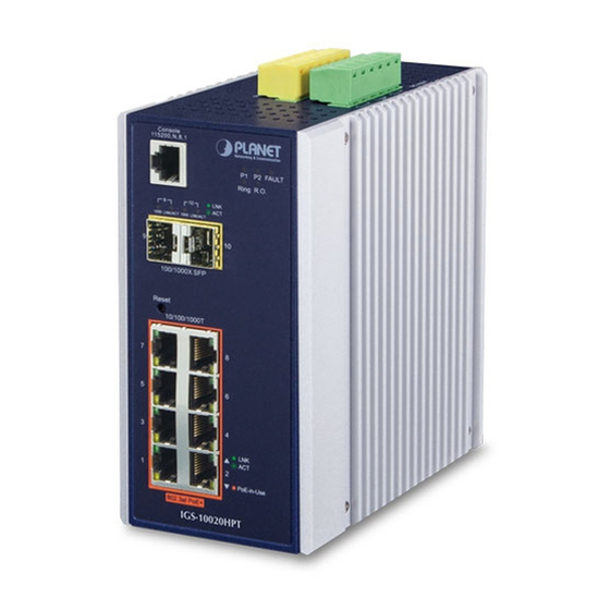
Page 25: Front Panel
User’s Manual of IGS-10020HPT-U 2.1.2 Front Panel IGS-10020HPT-U Figure 2-1: IGS-10020PT Switch Front Panel ■ Gigabit TP Interface 10/100/1000BASE-T Copper, RJ45 Twisted-pair: Up to 100 meters. ■ SFP Slot Triple-speed 100/1000/2500BASE-X SFP (small form-factor pluggable) fiber-optic modules, the distance can be extended from 300meters to 2km (multi-mode fiber) and to 10/20/30/40/60/70/80/120 kilometers (single-mode fiber or WDM fiber). - Page 26 User’s Manual of IGS-10020HPT-U IGS-10020HPT-U Figure 2-2: 10020HPT-U Reset Button Reset Button Pressed and Released Function < 5 sec: System Reboot Reboot the Industrial Managed PoE+ Switch. Reset the Industrial Managed PoE+ Switch to Factory Default configuration. The Industrial Managed PoE+ Switch will then reboot and load the default settings as shown below: 。...
-
Page 27: Led Indications
User’s Manual of IGS-10020HPT-U 2.1.3 LED Indications IGS-10020HPT-U System Color Function Green Lights to indicate power 1 has power. Lights to indicate power 2 has power. Green Alarm Lights to indicate either power 1 or power 2 has no power. -
Page 28: Switch Upper Panel
Insert positive/negative DC power wires into Contacts 1 and 2 for Power 1, or Contacts 5 and 6 for Power 2. IGS-10020HPT-U: 12V~54V DC Figure 2-3: IGS-10020HPT-U Upper Panel Tighten the wire-clamp screws for preventing the wires from loosening. Power 1... -
Page 29: Wiring The Fault Alarm Contact
User’s Manual of IGS-10020HPT-U 2.1.5 Wiring the Fault Alarm Contact The fault alarm contacts are in the middle (3 & 4) of the terminal block connector as the picture shows below. Inserting the wires, the Industrial Managed PoE+ Switch will detect the fault status of the power failure, or port link failure (available for managed model). - Page 30 User’s Manual of IGS-10020HPT-U Tighten the wire-clamp screws for preventing the wires from loosening. DI1 DO0 DO1 GND GND Figure 2-5: 6-pin Terminal Block for DI and DO Wiring Input There are two Digital Input groups for you to monitor two different devices. The following topology shows how to wire DI0 and DI1.
- Page 31 User’s Manual of IGS-10020HPT-U There are two Digital Output groups for you to sense Industrial Managed PoE+ Switch port failure or power failure and issue a high or low signal to external device. The following topology shows how to wire DO0 and DO1.
-
Page 32: Installing The Industrial Managed Poe+ Switch
User’s Manual of IGS-10020HPT-U 2.2 Installing the Industrial Managed PoE+ Switch This section describes how to install your Industrial Managed PoE+ Switch and make connections to the Industrial Managed PoE+ Switch. Please read the following topics and perform the procedures in the order being presented. To install your Industrial Managed PoE+ Switch on a desktop or shelf, simply complete the following steps. -
Page 33: Din-Rail Mounting
User’s Manual of IGS-10020HPT-U 2.2.2 DIN-rail Mounting This section describes how to install the Industrial Managed PoE+ Switch. There are two methods to install the Industrial Managed PoE+ Switch -- DIN-rail mounting and wall-mount plate mounting. Please read the following topics and perform the procedures in the order being presented. -
Page 34: Wall Mount Plate Mounting
User’s Manual of IGS-10020HPT-U 2.2.3 Wall Mount Plate Mounting To install the I Industrial Managed PoE+ Switch on the wall, please follow the instructions below. Follow all the DIN-rail installation steps as shown in the example. Step 1: Remove the DIN-rail bracket from the Industrial Managed PoE+ Switch. Use the screwdriver to loosen the screws to remove the bracket. -
Page 35: Cabling
User’s Manual of IGS-10020HPT-U 2.3 Cabling 10/100/1000BASE-T All 10/100/1000BASE-T ports come with auto-negotiation capability. They automatically support 1000BASE-T, 100BASE-TX and 10BASE-T networks. Users only need to plug a working network device into one of the 10/100/1000BASE-T ports, and then turn on the Industrial Managed PoE+ Switch. The port will automatically run at 10Mbps, 20Mbps, 100Mbps or 200Mbps and 1000Mbps or 2000Mbps after negotiating with the connected device. -
Page 36: Installing The Sfp Transceiver
Figure 2-8 : Plugging in the SFP Transceiver Approved PLANET SFP Transceivers PLANET Industrial Managed PoE+ Switch supports both single mode and multi-mode SFP transceivers. The following list of approved PLANET SFP transceivers is correct at the time of publication: Fast Ethernet Transceiver (100BASE-X SFP) - Page 37 User’s Manual of IGS-10020HPT-U -40~85℃ MFB-TFA40 WDM (LC) Single Mode 40km 1310nm 1550nm -40~85℃ MFB-TFB40 WDM (LC) Single Mode 40km 1550nm 1310nm -40~85℃ MFB-TSA WDM (LC) Multi- Mode 1310nm 1550nm -40~85℃ MFB-TSB WDM (LC) Multi- Mode 1550nm 1310nm Gigabit Ethernet Transceiver (1000BASE-X SFP)
- Page 38 WDM(LC) Single Mode 20km 1550nm 1310nm It is recommended to use PLANET SFP on the Industrial Managed PoE+ Switch. If you insert an SFP/SFP+ transceiver that is not supported, the Industrial Managed PoE+ Switch will not recognize it. Please choose the SFP transceiver which can be operated under -40~85 degrees C temperature if the switch device is working in a 0~50 degrees C temperature environment.
-
Page 39: Removing The Sfp/Sfp+ Transceiver
User’s Manual of IGS-10020HPT-U 2.3.2 Removing the SFP/SFP+ Transceiver Make sure there is no network activity by consulting or checking with the network administrator. Or through the management interface of the switch/converter (if available) to disable the port in advance. -
Page 40: Switch Management
User’s Manual of IGS-10020HPT-U 3. SWITCH MANAGEMENT This chapter explains the methods that you can use to configure management access to the Industrial Managed PoE+ Switch. It describes the types of management applications and the communication and management protocols that deliver data between your management device (workstation or personal computer) and the system. -
Page 41: Management Access Overview
User’s Manual of IGS-10020HPT-U 3.2 Management Access Overview The Industrial Managed PoE+ Switch gives you the flexibility to access and manage it using any or all of the following methods: An administration console Web browser interface An external SNMP-based network management application The administration console and Web browser interfaces are embedded in the Industrial Managed PoE+ Switch software and are available for immediate use. -
Page 42: Cli Mode Management
User’s Manual of IGS-10020HPT-U 3.3 CLI Mode Management To configure the system, connect a USB cable to a USB port on a PC or notebook computer and to the micro USB connector (console) of the Industrial Managed PoE+ Switch. Figure 3-1: Industrial Managed PoE+ Switch USB Console Connectivity The box of the Industrial Managed PoE+ Switch does not contain any USB cable. - Page 43 User’s Manual of IGS-10020HPT-U Figure 3-2: COM Port Configuration Remote Telnet In Windows system, you may click “Start” and then choose “Accessories” and “Command Prompt”. Please input “telnet 192.168.0.100” and press “enter’ from your keyboard. You will see the following screen appears as Figure 3-3 shows.
-
Page 44: Web Management
User’s Manual of IGS-10020HPT-U 3.4 Web Management The Industrial Managed PoE+ Switch offers management features that allow users to manage the Industrial Managed PoE+ Switch from anywhere on the network through a standard browser such as Microsoft Internet Explorer. After you set up your IP address for the Industrial Managed PoE+ Switch, you can access the Industrial Managed PoE+ Switch’s Web interface... -
Page 45: Snmp-Based Network Management
Figure 3-6: SNMP Management 3.6 PLANET Smart Discovery Utility To easily list the Industrial Managed PoE+ Switch in your Ethernet environment, the PLANET Smart Discovery Utility is an ideal solution. The following install instructions guide you to running the PLANET Smart Discovery Utility. - Page 46 To click the “Control Packet Force Broadcast” function, it allows new setting value to be assigned to the Web Smart Switch under a different IP subnet address. Press the “Connect to Device” button and then the Web login screen appears in Figure 3-5. Press the “Exit” button to shut down PLANET Smart Discovery Utility.
-
Page 47: Web Configuration
User’s Manual of IGS-10020HPT-U 4. WEB CONFIGURATION This section introduces the configuration and functions of the Web-based management. About Web-based Management The Industrial Managed PoE+ Switch offers management features that allow users to manage the Industrial Managed PoE+ Switch from anywhere on the network through a standard browser such as Google Chrome or Microsoft Edge. - Page 48 User’s Manual of IGS-10020HPT-U Figure 4-1-2: Login Screen Default User name: admin Default Password: admin After entering the username and password, the main screen appears as Figure 4-1-3. Figure 4-1-3: Default Main page Now, you can use the Web management interface to continue the switch management or manage the Industrial Managed PoE+ Switch by Web interface.
-
Page 49: Main Web Page
User’s Manual of IGS-10020HPT-U 4.1 Main Web page The Industrial Managed PoE+ Switch provides a Web-based browser interface for configuring and managing it. This interface allows you to access the Industrial Managed PoE+ Switch using the Web browser of your choice. This chapter describes how to use the Industrial Managed PoE+ Switch’s Web browser interface to configure and manage it. - Page 50 User’s Manual of IGS-10020HPT-U Main Menu Using the onboard web agent, you can define system parameters, manage and control the Industrial Managed PoE+ Switch, and all its ports, or monitor network conditions. Via the Web-Management, the administrator can set up the Industrial Managed PoE+ Switch by selecting the functions those listed in the Main Function.
-
Page 51: System
User’s Manual of IGS-10020HPT-U 4.2 System Use the System menu items to display and configure basic administrative details of the Industrial Managed PoE+ Switch. Under the System, the following topics are provided to configure and view the system information. This section has the following items: ■... -
Page 52: Management
User’s Manual of IGS-10020HPT-U 4.2.1 Management 4.2.1.1 System Information The System Infomation page provides information for the current device information. System Information page helps a switch administrator to identify the hardware MAC address, software version and system uptime. The screen in Figure 4-2-1 appears. -
Page 53: Ip Configuration
User’s Manual of IGS-10020HPT-U 4.2.1.2 IP Configuration The IP Configuration includes the IP Configuration, IP Interface and IP Routes. The configured column is used to view or change the IP configuration. The maximum number of interfaces supported is 128 and the maximum number of routes is 32. - Page 54 User’s Manual of IGS-10020HPT-U Configured IPv6 Explicitly provide the valid IPv6 unicast (except linklocal) address of the DNS Server. Make sure the configured DNS server could be reachable (e.g. via PING6) for activating DNS service. From any DHCPv4 interfaces The first DNS server offered from a DHCPv4 lease to a DHCPv4-enabled interface will be used.
- Page 55 User’s Manual of IGS-10020HPT-U The IPv4 network mask, in number of bits (prefix length). Valid values Mask Length are between 0 and 30 bits for a IPv4 address. If DHCP is enabled, this field configures the fallback address network mask. The field may be left blank if IPv4 operation on the interface is not desired - or no DHCP fallback address is desired.
- Page 56 User’s Manual of IGS-10020HPT-U same type. The VLAN ID (VID) of the specific IPv6 interface associated with the Next Hop VLAN gateway. The given VID ranges from 1 to 4095 and will be effective only when the corresponding IPv6 interface is valid.
-
Page 57: Ip Status
User’s Manual of IGS-10020HPT-U 4.2.1.3 IP Status IP Status displays the status of the IP protocol layer. The status is defined by the IP interfaces, the IP routes and the neighbor cache (ARP cache) status. The screen in Figure 4-2-3 appears. -
Page 58: Arp
User’s Manual of IGS-10020HPT-U 4.2.1.4 ARP This page provides an overview of the aging time setting, press the “Apply” button to take effect, the screen in Figure 4-2-4 appears. Figure 4-2-4: ARP Configuration Page Screenshot 4.2.1.5 Users Configuration This page provides an overview of the current users. Currently the only way to login as another user on the web server is to close and reopen the browser. - Page 59 User’s Manual of IGS-10020HPT-U By default setting, most groups privilege level 5 has the read-only access and privilege level 10 has the read-write access. And the system maintenance (software upload, factory defaults and etc.) needs user privilege level 15. Generally, the privilege level 15 can be used for an administrator account, privilege level 10 for a standard user account and privilege level 5 for a guest account.
- Page 60 User’s Manual of IGS-10020HPT-U By default setting, most groups privilege level 5 has the read-only access and privilege level 10 has the read-write access. And the system maintenance (software upload, factory defaults and etc.) needs user privilege level 15. Generally, the privilege level 15 can be used for an administrator account, privilege level 10 for a standard user account and privilege level 5 for a guest account.
-
Page 61: Privilege Levels
User’s Manual of IGS-10020HPT-U 4.2.1.6 Privilege Levels This page provides an overview of the privilege levels. After setup is completed, please press the “Apply” button to take effect. Please login web interface with new user name and password and the screen in Figure 4-2-8 appears. - Page 62 User’s Manual of IGS-10020HPT-U The page includes the following fields: Object Description • Group Name The name identifying the privilege group. In most cases, a privilege level group consists of a single module (e.g. LACP, RSTP or QoS), but a few of them contain more than one.
-
Page 63: Ntp Configuration
User’s Manual of IGS-10020HPT-U 4.2.1.7 NTP Configuration Configure NTP on this page. NTP is an acronym for Network Time Protocol, a network protocol for synchronizing the clocks of computer systems. NTP uses UDP (data grams) as transport layer. You can specify NTP Servers. The NTP Configuration... -
Page 64: System Time Correction Manually
User’s Manual of IGS-10020HPT-U 4.2.1.7.1 System Time Correction Manually Configure NTP on this page. NTP is an acronym for Network Time Protocol, a network protocol for synchronizing the clocks of computer systems. NTP uses UDP (data grams) as transport layer. You can specify NTP Servers. The NTP Configuration... -
Page 65: Time Configuration
User’s Manual of IGS-10020HPT-U 4.2.1.8 Time Configuration Configure Time Zone on this page. A Time Zone is a region that has a uniform standard time for legal, commercial, and social purposes. It is convenient for areas in close commercial or other communication to keep the same time, so time zones tend to follow the boundaries of countries and their subdivisions. - Page 66 User’s Manual of IGS-10020HPT-U The page includes the following fields: Object Description • Time Zone Lists various Time Zones worldwide. Select appropriate Time Zone from the drop-down and click Save to set. • Acronym User can set the acronym of the time zone. This is a User configurable acronym to identify the time zone.
-
Page 67: Upnp
User’s Manual of IGS-10020HPT-U 4.2.1.9 UPnP Configure UPnP on this page. UPnP is an acronym for Universal Plug and Play. The goals of UPnP are to allow devices to connect seamlessly and to simplify the implementation of networks in the home (data sharing, communications, and entertainment) and in corporate environments for simplified installation of computer components. -
Page 68: Dhcp Relay
User’s Manual of IGS-10020HPT-U 4.2.1.10 DHCP Relay Configure DHCP Relay on this page. DHCP Relay is used to forward and transfer DHCP messages between the clients and the server when they are not on the same subnet domain. The DHCP option 82 enables a DHCP relay agent to insert specific information into a DHCP request packets when forwarding client DHCP packets to a DHCP server and remove the specific information from a DHCP reply packets when forwarding server DHCP packets to a DHCP client. - Page 69 User’s Manual of IGS-10020HPT-U • Relay Information Indicates the DHCP relay information mode option operation. Possible modes Mode are: Enabled: Enable DHCP relay information mode operation. When enabling DHCP relay information mode operation, the agent inserts specific information (option82) into a DHCP message when forwarding to DHCP server and removing it from a DHCP message when transferring to DHCP client.
-
Page 70: Dhcp Relay Statistics
User’s Manual of IGS-10020HPT-U 4.2.1.11 DHCP Relay Statistics This page provides statistics for DHCP relay. The DHCP Relay Statistics screen in Figure 4-2-14 appears. Figure 4-2-14: DHCP Relay Statistics Page Screenshot The page includes the following fields: Server Statistics Object Description •... - Page 71 User’s Manual of IGS-10020HPT-U Client Statistics Object Description • Transmit to Client The packets number that relayed packets from server to client. • Transmit Error The packets number that erroneously sent packets to servers. • Receive from Client The packets number that received packets from server.
-
Page 72: Cpu Load
User’s Manual of IGS-10020HPT-U 4.2.1.12 CPU Load This page displays the CPU load, using an SVG graph. The load is measured as average over the last 100ms, 1 sec and 10 seconds intervals. The last 120 samples are graphed, and the last numbers are displayed as text as well. In order to display the SVG graph, your browser must support the SVG format. -
Page 73: System Log
User’s Manual of IGS-10020HPT-U 4.2.1.13 System Log The Industrial Managed PoE+ Switch system log information is provided here. The System Log screen in Figure 4-2-16 appears. Figure 4-2-16: System Log Page Screenshot The page includes the following fields: Object Description •... -
Page 74: Detailed Log
User’s Manual of IGS-10020HPT-U 4.2.1.14 Detailed Log The Industrial Managed PoE+ Switch system detailed log information is provided here. The Detailed Log screen in Figure 4-2-17 appears. Figure 4-2-17: Detailed Log Page Screenshot The page includes the following fields: Object Description •... -
Page 75: Remote Syslog
User’s Manual of IGS-10020HPT-U 4.2.1.15 Remote Syslog Configure remote syslog on this page. The Remote Syslog screen in Figure 4-2-18 appears. Figure 4-2-18: Remote Syslog Page Screenshot The page includes the following fields: Object Description • Mode Indicates the server mode operation. When the mode operation is enabled, the syslog message will send out to syslog server. -
Page 76: Smtp Configuration
User’s Manual of IGS-10020HPT-U 4.2.1.16 SMTP Configuration This page facilitates an SMTP Configuration on the switch. The SMTP Configure screen in Figure 4-2-19 appears. Figure 4-2-19: SMTP Configuration Page Screenshot The page includes the following fields: Object Description • SMTP Mode Controls whether SMTP is enabled on this switch. -
Page 77: Fault Alarm
User’s Manual of IGS-10020HPT-U 4.2.1.17 Fault Alarm This page facilitates an update of the firmware controlling the switch. The Web Firmware Upgrade screen in Figure 4-2-20 appears. Figure 4-2-20: Fault Alarm Control Configuration page Screenshot The page includes the following fields:... -
Page 78: Digital Input/Output
User’s Manual of IGS-10020HPT-U 4.2.1.18 Digital Input/Output Digital Input allows user to log external device (such as industrial cooler) dead or alive or something else. System will log a user customized message into system log and syslog, and issue SNMP trap or issue an alarm E-mail. - Page 79 User’s Manual of IGS-10020HPT-U want to issue alarm message via them. As Digital Output: Allows user to monitor an alarm from port failure, power failure, Digital Input 0 (DI 0) and Digital Input 1(DI 1) which means if Digital Output has detected these events, then Digital Output would be triggered according to the setting of Condition.
-
Page 80: Simple Network Management Protocol
User’s Manual of IGS-10020HPT-U 4.2.2 Simple Network Management Protocol 4.2.2.1 SNMP Overview The Simple Network Management Protocol (SNMP) is an application layer protocol that facilitates the exchange of management information between network devices. It is part of the Transmission Control Protocol/Internet Protocol (TCP/IP) protocol suite. -
Page 81: Snmp System Configuration
User’s Manual of IGS-10020HPT-U Use the SNMP Menu to display or configure the Industrial Managed PoE+ Switch 's SNMP function. This section has the following items: System Configuration Configure SNMP on this page. System Information The system information is provided here. -
Page 82: Snmp System Information
User’s Manual of IGS-10020HPT-U 4.2.2.3 SNMP System Information The switch system information is provided here. The SNMP System Information screen in Figure 4-2-2-3 appears. Figure 4-2-2-3: System Information Configuration Page Screenshot The page includes the following fields: Object Description •... -
Page 83: Snmp Trap Configuration
User’s Manual of IGS-10020HPT-U 4.2.2.4 SNMP Trap Configuration Configure SNMP trap on this page. The SNMP Trap Configuration screen in Figure 4-2-2-4 appears. Figure 4-2-2-4: SNMP Trap Configuration Page Screenshot The page includes the following fields: Object Description • Indicates which trap Configuration's name for configuring. The allowed string Trap Config length is 0 to 255, and the allowed content is ASCII characters from 33 to 126. - Page 84 User’s Manual of IGS-10020HPT-U • Trap Inform Mode Indicates the SNMP trap inform mode operation. Possible modes are: Enabled: Enable SNMP trap authentication failure. Disabled: Disable SNMP trap authentication failure. • Trap Inform Timeout Indicates the SNMP trap inform timeout.
-
Page 85: Snmp Trap Source Configuration
User’s Manual of IGS-10020HPT-U 4.2.2.5 SNMP Trap Source Configuration This page provides SNMP trap source configurations. A trap is sent for the given trap source if at least one filter with filter type included matches the filter, and no filters with filter type excluded matches. -
Page 86: Snmpv3 Communities
User’s Manual of IGS-10020HPT-U 4.2.2.6 SNMPv3 Communities Configure SNMPv3 communities table on this page. The entry index key is Community. The SNMPv3 Communities screen in Figure 4-2-2-7 appears. Figure 4-2-2-7: SNMPv3 Communities Configuration Page Screenshot The page includes the following fields:... -
Page 87: Snmpv3 Users
User’s Manual of IGS-10020HPT-U 4.2.2.7 SNMPv3 Users Configure SNMPv3 users table on this page. The entry index keys are Engine ID and User Name. The SNMPv3 Users screen in Figure 4-2-2-8 appears. Figure 4-2-2-8: SNMPv3 Users Configuration Page Screenshot The page includes the following fields:... - Page 88 User’s Manual of IGS-10020HPT-U MD5: An optional flag to indicate that this user using MD5 authentication protocol. SHA: An optional flag to indicate that this user using SHA authentication protocol. The value of security level cannot be modified if entry already exist. That means must first ensure that the value is set correctly.
-
Page 89: Snmpv3 Groups
User’s Manual of IGS-10020HPT-U 4.2.2.8 SNMPv3 Groups Configure SNMPv3 groups table on this page. The entry index keys are Security Model and Security Name. The SNMPv3 Groups screen in Figure 4-2-2-9 appears. Figure 4-2-2-9: SNMPv3 Groups Configuration Page Screenshot The page includes the following fields:... -
Page 90: Snmpv3 Views
User’s Manual of IGS-10020HPT-U 4.2.2.9 SNMPv3 Views Configure SNMPv3 views table on this page. The entry index keys are View Name and OID Subtree. The SNMPv3 Views screen in Figure 4-2-2-10 appears. Figure 4-2-2-10: SNMPv3 Views Configuration Page Screenshot The page includes the following fields:... -
Page 91: Snmpv3 Access
User’s Manual of IGS-10020HPT-U 4.2.2.10 SNMPv3 Access Configure SNMPv3 accesses table on this page. The entry index keys are Group Name, Security Model and Security Level. The SNMPv3 Access screen in Figure 4-2-2-11 appears. Figure 4-2-2-11: SNMPv3 Accesses Configuration Page Screenshot... -
Page 92: Rmon
User’s Manual of IGS-10020HPT-U 4.2.3 RMON RMON is the most important expansion of the standard SNMP. RMON is a set of MIB definitions, used to define standard network monitor functions and interfaces, enabling the communication between SNMP management terminals and remote monitors. - Page 93 User’s Manual of IGS-10020HPT-U InNUcastPkts: The number of broadcast and multi-cast packets delivered to a higher-layer protocol. InDiscards: The number of inbound packets that are discarded even the packets are normal. InErrors: The number of inbound packets that contains errors preventing them from being deliverable to a higher-layer protocol.
-
Page 94: Rmon Alarm Status
User’s Manual of IGS-10020HPT-U 4.2.3.2 RMON Alarm Status This page provides an overview of RMON Alarm entries. Each page shows up to 99 entries from the Alarm table, default being 20, selected through the "entries per page" input field. When first visited, the web page will show the first 20 entries from the beginning of the Alarm table. -
Page 95: Rmon Event Configuration
User’s Manual of IGS-10020HPT-U 4.2.3.3 RMON Event Configuration Configure RMON Event table on this page. The entry index key is ID; screen in Figure 4-2-3-3 appears. Figure 4-2-3-3 RMON Event Configuration Page Screenshot The page includes the following fields: Object Description •... -
Page 96: Rmon Event Status
User’s Manual of IGS-10020HPT-U 4.2.3.4 RMON Event Status This page provides an overview of RMON Event table entries. Each page shows up to 99 entries from the Event table, default being 20, selected through the "entries per page" input field. When first visited, the web page will show the first 20 entries from the beginning of the Event table. -
Page 97: Rmon History Configuration
User’s Manual of IGS-10020HPT-U 4.2.3.5 RMON History Configuration Configure RMON History table on this page. The entry index key is ID; screen in Figure 4-2-3-5 appears. Figure 4-2-3-5: RMON History Configuration Page Screenshot The page includes the following fields: Object Description •... -
Page 98: Rmon History Status
User’s Manual of IGS-10020HPT-U 4.2.3.6 RMON History Status This page provides an detail of RMON history entries; screen in Figure 4-2-3-6 appears. Figure 4-2-3-6: RMON History Overview Page Screenshot The page includes the following fields: Object Description • History Index Indicates the index of History control entry. -
Page 99: Rmon Statistics Configuration
User’s Manual of IGS-10020HPT-U 4.2.3.7 RMON Statistics Configuration Configure RMON Statistics table on this page. The entry index key is ID; screen in Figure 4-2-3-7 appears. Figure 4-2-3-7: RMON Statistics Configuration Page Screenshot The page includes the following fields: Object Description •... - Page 100 User’s Manual of IGS-10020HPT-U The page includes the following fields: Object Description • ID Indicates the index of Statistics entry. • Data Source (ifIndex) The port ID which wants to be monitored. • Drop The total number of events in which packets were dropped by the probe due to lack of resources.
-
Page 101: Dhcp Server
User’s Manual of IGS-10020HPT-U 4.2.4 DHCP server 4.2.4.1 DHCP Server Mode Configuration Configure DHCP server mode on this page. The entry index key is ID.; screen in Figure 4-2-4-1 appears. Figure 4-2-4-1: DHCP server mode Page Screenshot The page includes the following fields:... -
Page 102: Dhcp Server Excluded Ip Configuration
User’s Manual of IGS-10020HPT-U 4.2.4.2 DHCP Server excluded IP Configuration Configure excluded IP addresses. DHCP server will not allocate these excluded IP addresses to DHCP client.; screen in Figure 4-2-4-2 appears. Figure 4-2-4-2: DHCP server excluded Page Screenshot The page includes the following fields:... -
Page 103: Dhcp Server Pool Configuration
User’s Manual of IGS-10020HPT-U 4.2.4.3 DHCP Server pool Configuration This page manages DHCP pools. According to the DHCP pool, DHCP server will allocate IP address and deliver configuration parameters to DHCP client. screen in Figure 4-2-4-3 appears. Figure 4-2-4-3: DHCP server pool Page Screenshot... -
Page 104: Dhcp Server Pool Configuration
User’s Manual of IGS-10020HPT-U 4.2.4.4 DHCP Server pool Configuration This page displays the database counters and the number of DHCP messages sent and received by DHCP server. screen in Figure 4-2-4-4 appears. Figure 4-2-4-4: DHCP server Statistics Page Screenshot The page includes the following fields:... - Page 105 User’s Manual of IGS-10020HPT-U DHCP message Received Counters Object Description • Discover Number of DHCP DISCOVER messages received. • Request Number of DHCP REQUEST messages received. • Decline Number of DHCP DECLINE messages received. • Release Number of DHCP RELEASE messages received.
-
Page 106: Dhcp Server Binding Ip Configuration
User’s Manual of IGS-10020HPT-U 4.2.4.5 DHCP Server Binding IP Configuration This page displays bindings generated for DHCP clients. screen in Figure 4-2-4-5 appears. Figure 4-2-4-5: DHCP server Binding IP page Screenshot The page includes the following fields: Object Description • IP Display IP address allocated to DHCP client. -
Page 107: Dhcp Server Declined Ip
User’s Manual of IGS-10020HPT-U 4.2.4.6 DHCP Server Declined IP This page displays declined IP addresses. screen in Figure 4-2-4-6 appears. Figure 4-2-4-6: DHCP server Declined IP Page Screenshot The page includes the following fields: Object Description • Delined IP Display List of IP addresses declined. -
Page 108: Dhcp Detail Statistics
User’s Manual of IGS-10020HPT-U 4.2.4.7 DHCP Detail Statistics This page provides statistics for DHCP snooping. Notice that the normal forward per-port TX statistics isn't increased if the incoming DHCP packet is done by L3 forwarding mechanism. And clear the statistics on specific port may not take effect on global statistics since it gathers the different layer overview. -
Page 109: Industrial Protocol
User’s Manual of IGS-10020HPT-U 4.2.5 Industrial Protocol With the supported Modbus TCP/IP protocol, the IGS-5225 series can easily integrate with SCADA systems, HMI systems and other data acquisition systems in factory floors. It enable administrators to remotely monitor the industrial Ethernet switch’s operating information, port information and communication status, thus easily achieving enhanced monitoring... -
Page 110: Remote Management
APs, VoIP phones, IP cameras, etc., compliant with the SNMP Protocol, ONVIF Protocol and PLANET Smart Discovery utility. The CloudViewer is a free networking service just for PLANET Products. This service provides simplified network monitoring and real-time network status. Working with PLANET CloudViewer app, user can easily check network status, device information, Port and PoE status from Internet. -
Page 111: Switching
User’s Manual of IGS-10020HPT-U 4.3 Switching 4.3.1 Port Management Use the Port Menu to display or configure the Industrial Managed PoE+ Switch's ports. This section has the following items: Port Configuration Configures port connection settings Port Statistics Overview Lists Ethernet and RMON port statistics ... - Page 112 User’s Manual of IGS-10020HPT-U The page includes the following fields: Object Description • Port This is the logical port number for this row. • Port Description Indicates the per port description. • The current link state is displayed graphically. Green indicates the link is up and Link red indicates the link is down.
-
Page 113: Port Statistics Overview
User’s Manual of IGS-10020HPT-U 4.3.1.2 Port Statistics Overview This page provides an overview of general traffic statistics for all switch ports. The Port Statistics Overview screen in Figure 4-3-1-2 appears. Figure 4-3-1-2: Port Statistics Overview Page Screenshot The displayed counters are:... -
Page 114: Port Statistics Details
User’s Manual of IGS-10020HPT-U 4.3.1.3 Port Statistics Details This page provides detailed traffic statistics for a specific switch port. Use the port select box to select which switch port details to display. The displayed counters are the totals for receive and transmit, the size counters for receive and transmit, and the error counters for receive and transmit. - Page 115 User’s Manual of IGS-10020HPT-U Receive and Transmit Size Counters The number of received and transmitted (good and bad) packets split into categories based on their respective frame sizes. Receive and Transmit Queue Counters The number of received and transmitted packets per input and output queue.
-
Page 116: Sfp Module Information
User’s Manual of IGS-10020HPT-U 4.3.1.4 SFP Module Information The Industrial Managed PoE+ Switches have supported the SFP module with digital diagnostics monitoring (DDM) function. This feature is also known as digital optical monitoring (DOM). You can check the physical or operational status of an SFP module via the SFP Module Information page. This page shows the operational status, such as the transceiver type, speed, wavelength, optical output power, optical input power, temperature, laser bias current and transceiver supply voltage in real time. - Page 117 User’s Manual of IGS-10020HPT-U • Voltage(V) Display the voltage of current SFP DDM module; the voltage value is got from the – SFP DDM Module Only SFP DDM module. • Current(mA) Display the Ampere of current SFP DDM module; the Ampere value is got from –...
-
Page 118: Port Mirror
User’s Manual of IGS-10020HPT-U 4.3.1.5 Port Mirror Configure port Mirroring on this page. This function provides monitoring network traffic that forwards a copy of each incoming or outgoing packet from one port of a network Switch to another port where the packet can be studied. It enables the manager to keep close track of switch performance and alter it if necessary. - Page 119 User’s Manual of IGS-10020HPT-U Figure 4-3-1-7: Mirror Configuration Page Screenshot The page includes the following fields: Object Description • Session Select session id to configure. • Mode To Enabled/Disabled the mirror or Remote Mirroring function • Type Mirror The switch is running on mirror mode.
- Page 120 User’s Manual of IGS-10020HPT-U • Reflector Port The reflector port is a method to redirect the traffic to Remote Mirroring VLAN. Any device connected to a port set as a reflector port loses connectivity until the Remote Mirroring is disabled.
-
Page 121: Link Aggregation
User’s Manual of IGS-10020HPT-U 4.3.2 Link Aggregation Port Aggregation optimizes port usage by linking a group of ports together to form a single Link Aggregated Groups (LAGs). Port Aggregation multiplies the bandwidth between the devices, increases port flexibility, and provides link redundancy. - Page 122 User’s Manual of IGS-10020HPT-U The Link Aggregation Control Protocol (LACP) provides a standardized means for exchanging information between Partner Systems that require high speed redundant links. Link aggregation lets you group up to eight consecutive ports into a single dedicated connection. This feature can expand bandwidth to a device on the network. LACP operation requires full-duplex mode, more detail information refer to the IEEE 802.3ad standard.
-
Page 123: Static Aggregation
User’s Manual of IGS-10020HPT-U 4.3.2.1 Static Aggregation This page is used to configure the Aggregation hash mode and the aggregation group. The aggregation hash mode settings are global. Hash Code Contributors The Static Aggregation screen in Figure 4-3-2-2 appears. Figure 4-3-2-2 : Aggregation Mode Configuration Page Screenshot... - Page 124 User’s Manual of IGS-10020HPT-U Figure 4-3-2-3: Aggregation Group Configuration Page Screenshot The page includes the following fields: .Object Description • Group ID Indicates the group ID for the settings contained in the same row. Group ID "Normal" indicates there is no aggregation. Only one group ID is valid per port.
-
Page 125: Static Aggregation Status
User’s Manual of IGS-10020HPT-U 4.3.2.2 Static Aggregation Status This page is used to see the staus of ports in Aggregation group. The Static Aggregation Status screen in Figure 4-3-2-4 appears. Figure 4-3-2-4 : LACP Port Configuration Page Screenshot The page includes the following fields:... - Page 126 User’s Manual of IGS-10020HPT-U Figure 4-3-2-5 : LACP Port Configuration Page Screenshot The page includes the following fields: Object Description • Port The switch port number. • Controls whether LACP is enabled on this switch port. LACP will form an aggregation when 2 LACP Enabled or more ports are connected to the same partner.
-
Page 127: Lacp System Status
User’s Manual of IGS-10020HPT-U 4.3.2.4 LACP System Status This page provides a status overview of all LACP instances. The LACP Status Page display the current LACP aggregation Groups and LACP Port status. The LACP System Status screen in Figure 4-3-2-6 appears. -
Page 128: Lacp Port Status
User’s Manual of IGS-10020HPT-U 4.3.2.5 LACP Port Status This page provides a status overview of LACP status for all ports. The LACP Port Status screen in Figure 4-5-2-7 appears. Figure 4-3-2-7: LACP Status Page Screenshot The page includes the following fields:... -
Page 129: Lacp Port Statistics
User’s Manual of IGS-10020HPT-U 4.3.2.6 LACP Port Statistics This page provides an overview for LACP statistics for all ports. The LACP Port Status screen in Figure 4-5-2-8 appears. Figure 4-3-2-8: LACP Port Statistics Page Screenshot The page includes the following fields:... -
Page 130: Vlan
User’s Manual of IGS-10020HPT-U 4.3.3 VLAN 4.3.3.1 VLAN Overview A Virtual Local Area Network (VLAN) is a network topology configured according to a logical scheme rather than the physical layout. VLAN can be used to combine any collection of LAN segments into an autonomous user group that appears as a single LAN. -
Page 131: Ieee 802.1Q Vlan
User’s Manual of IGS-10020HPT-U 4.3.3.2 IEEE 802.1Q VLAN In large networks, routers are used to isolate broadcast traffic for each subnet into separate domains. This Industrial Managed PoE+ Switch provides a similar service at Layer 2 by using VLANs to organize any group of network nodes into separate broadcast domains. - Page 132 User’s Manual of IGS-10020HPT-U ■ 802.1Q VLAN Tags The figure below shows the 802.1Q VLAN tag. There are four additional octets inserted after the source MAC address. Their presence is indicated by a value of 0x8100 in the Ether Type field. When a packet's Ether Type field is equal to 0x8100, the packet carries the IEEE 802.1Q/802.1p tag.
- Page 133 User’s Manual of IGS-10020HPT-U Tag-aware switches must keep a table to relate PVID within the switch to VID on the network. The switch will compare the VID of a packet to be transmitted to the VID of the port that is to transmit the packet. If the two VID are different the switch will drop the packet.
-
Page 134: Vlan Port Configuration
User’s Manual of IGS-10020HPT-U 4.3.3.3 VLAN Port Configuration This page is used for configuring the Industrial Managed PoE+ Switch port VLAN. The VLAN per Port Configuration page contains fields for managing ports that are part of a VLAN. The port default VLAN ID (PVID) is configured on the VLAN Port Configuration page. - Page 135 User’s Manual of IGS-10020HPT-U The Industrial Managed PoE+ Switch supports multiple VLAN tags and can therefore be used in MAN applications as a provider bridge, aggregating traffic from numerous independent customer LANs into the MAN (Metro Access Network) space. One of the purposes of the provider bridge is to recognize and use VLAN tags so that the VLANs in the MAN space can be used independent of the customers’...
- Page 136 User’s Manual of IGS-10020HPT-U The page includes the following fields: Object Description • Allowed Access This field shows the allowed Access VLANs, it only affects ports configured as VLANs Access ports. Ports in other modes are members of all VLANs specified in the Allowed VLANs field.
- Page 137 User’s Manual of IGS-10020HPT-U The page includes the following fields: Object Description • Port This is the logical port number for this row. • Mode Access Access ports are normally used to connect to end stations. Dynamic features like Voice VLAN may add the port to more VLANs behind the scenes. Access ports have the following characteristics: •...
- Page 138 User’s Manual of IGS-10020HPT-U Tagging configuration is set to untag Port VLAN. The Port VLAN is called an "Access VLAN" for ports in Access mode and Native VLAN for ports in Trunk or Hybrid mode. • Port Type Ports in hybrid mode allow for changing the port type, that is, whether a frame's VLAN tag is used to classify the frame on ingress to a particular VLAN, and if so, which TPID it reacts on.
- Page 139 User’s Manual of IGS-10020HPT-U discarded. ■ Untagged Only Only untagged frames are accepted on ingress. Tagged frames are discarded. Egress Tagging This option is only available for ports in Hybrid mode. Ports in Trunk and Hybrid mode may control the tagging of frames on egress.
-
Page 140: Vlan Membership Status
User’s Manual of IGS-10020HPT-U 4.3.3.4 VLAN Membership Status This page provides an overview of membership status for VLAN users. The VLAN Membership Status screen in Figure 4-3-3-3 appears. Figure 4-3-3-3: VLAN Membership Status for Static User Page Screenshot The page includes the following fields:... -
Page 141: Vlan Port Status
User’s Manual of IGS-10020HPT-U • The VLAN Membership Status page shall show the current VLAN port members VLAN Membership for all VLANs configured by a selected VLAN User (selection shall be allowed by a Combo Box). When ALL VLAN Users are selected, it shall show this information for all the VLAN Users, and this is by default. -
Page 142: Private Vlan
User’s Manual of IGS-10020HPT-U The page includes the following fields: Object Description • Port The logical port for the settings contained in the same row. • Port Type Show the VLAN Awareness for the port. If VLAN awareness is enabled, the tag is removed from tagged frames received on the port. - Page 143 User’s Manual of IGS-10020HPT-U A port must be a member of both a VLAN and a Private VLAN to be able to forward packets. By default, all ports are VLAN unaware and members of VLAN 1 and Private VLAN 1.
-
Page 144: Port Isolation
User’s Manual of IGS-10020HPT-U 4.3.3.7 Port Isolation Overview When a VLAN is configured to be a private VLAN, communication between ports within that VLAN can be prevented. Two application examples are provided in this section: • Customers connected to an ISP can be members of the same VLAN, but they are not allowed to communicate with each other within that VLAN. - Page 145 User’s Manual of IGS-10020HPT-U The configuration of promiscuous and isolated ports applies to all private VLANs. When traffic comes in on a promiscuous port in a private VLAN, the VLAN mask from the VLAN table is applied. When traffic comes in on an isolated port, the private VLAN mask is applied in addition to the VLAN mask from the VLAN table.
-
Page 146: Vlan Setting Example
User’s Manual of IGS-10020HPT-U 4.3.3.8 VLAN setting example: Separate VLAN 802.1Q VLAN Trunk Port Isolate 4.3.3.8.1 Two Separate 802.1Q VLANs The diagram shows how the Industrial Managed PoE+ Switch handle Tagged and Untagged traffic flow for two VLANs. VLAN Group 2 and VLAN Group 3 are separated VLAN. - Page 147 User’s Manual of IGS-10020HPT-U The scenario is described as follows: Untagged packet entering VLAN 2 While [PC-1] transmit an untagged packet enters Port-1, the Industrial Managed PoE+ Switch will tag it with a VLAN Tag=2. [PC-2] and [PC-3] will received the packet through Port-2 and Port-3.
- Page 148 User’s Manual of IGS-10020HPT-U Assign VLAN Member and PVID for each port: VLAN 2 : Port-1,Port-2 and Port-3 VLAN 3 : Port-4, Port-5 and Port-6 VLAN 1 : All other ports – Port-7~Port-52 Figure 4-3-3-9: Change Port VLAN of Port 1~3 to be VLAN2 and Port VLAN of Port 4~6 to be VLAN3...
-
Page 149: Vlan Trunking Between Two 802.1Q Aware Switches
User’s Manual of IGS-10020HPT-U 4.3.3.8.2 VLAN Trunking between two 802.1Q aware switches The most cases are used for “Uplink” to other switches. VLANs are separated at different switches, but they need to access with other switches within the same VLAN group. The screen in Figure 4-3-3-11 appears. - Page 150 User’s Manual of IGS-10020HPT-U Figure 4-3-3-13: Changes Port VLAN of Port 1~3 to be VLAN2 and Port VLAN of Port 4~6 to be VLAN3 For the VLAN ports connecting to the hosts, please refer to 4.6.10.1 examples. The following steps will focus on the VLAN Trunk port configuration.
-
Page 151: Port Isolate
User’s Manual of IGS-10020HPT-U 4.3.3.8.3 Port Isolate The diagram shows how the Industrial Managed PoE+ Switch handles isolated and promiscuous ports, and the each PC is not able to access the isolated port of each other’s PCs. But they all need to access with the same server/AP/Printer. This section will show you how to configure the port for the server –... -
Page 152: Mac-Based Vlan
User’s Manual of IGS-10020HPT-U 4.3.3.9 MAC-based VLAN The MAC-based VLAN entries can be configured here. This page allows for adding and deleting MAC-based VLAN entries and assigning the entries to different ports. This page shows only static entries. The MAC-based VLAN screen in Figure 4-3-3-16 appears. -
Page 153: Ip Subnet-Based Vlan Membership Configuration
User’s Manual of IGS-10020HPT-U 4.3.3.10 IP Subnet-based VLAN Membership Configuration The IP subnet to VLAN ID mappings can be configured here. This page allows adding, updating and deleting IP subnet to VLAN ID mapping entries and assigning them to different ports. The MAC-based VLAN screen in Figure 4-3-3-17 appears. -
Page 154: Protocol-Based Vlan
User’s Manual of IGS-10020HPT-U 4.3.3.11 Protocol-based VLAN This page allows you to add new protocols to Group Name (unique for each Group) mapping entries as well as allow you to see and delete already mapped entries for the switch. The Protocol-based VLAN screen in Figure 4-3-3-18 appears. - Page 155 User’s Manual of IGS-10020HPT-U xx-xx-xx where each pair (xx) in string is a hexadecimal value ranges from 0x00-0xff. PID: If the OUI is hexadecimal 000000, the protocol ID is the Ethernet type (EtherType) field value for the protocol running on top of SNAP;...
-
Page 156: Protocol-Based Vlan Membership
User’s Manual of IGS-10020HPT-U 4.3.3.12 Protocol-based VLAN Membership This page allows you to map a already configured Group Name to a VLAN for the switch. The Group Name to VLAN Mapping Table screen in Figure 4-3-3-19 appears. Figure 4-3-3-19: Group Name to VLAN Mapping Table Page Screenshot... -
Page 157: Port To Group Configuration
User’s Manual of IGS-10020HPT-U 4.3.4 Port to Group Configuration This page allows you to configure switch Ports to use a given VLAN Translation Mapping Group. This will enable all VLAN Translation mappings of that group (if any) on the selected switch port. The VLAN Translation screen in Figure 4-3-3-20 appears. -
Page 158: Vlan Translation Mappings
User’s Manual of IGS-10020HPT-U 4.3.5 VLAN Translation Mappings This page allows you to create mappings of VLANs -> Translated VLANs and organize these mappings into global Groups. The VLAN Translation Mapping Table screen in Figure 4-3-3-21 appears. Figure 4-3-3-21: VLAN Translation Mapping Table Page Screenshot... -
Page 159: Spanning Tree Protocol
User’s Manual of IGS-10020HPT-U 4.3.6 Spanning Tree Protocol 4.3.6.1 Theory The Spanning Tree protocol can be used to detect and disable network loops, and to provide backup links between switches, bridges or routers. This allows the switch to interact with other bridging devices in your network to ensure that only one route exists between any two stations on the network, and provide backup links which automatically take over when a primary link goes down. - Page 160 User’s Manual of IGS-10020HPT-U The switch sends BPDUs to communicate and construct the spanning-tree topology. All switches connected to the LAN on which the packet is transmitted will receive the BPDU. BPDUs are not directly forwarded by the switch, but the receiving switch uses the information in the frame to calculate a BPDU, and, if the topology changes, initiates a BPDU transmission.
- Page 161 User’s Manual of IGS-10020HPT-U Figure 4-3-6-1: STP Port State Transitions You can modify each port state by using management software. When you enable STP, every port on every switch in the network goes through the blocking state and then transitions through the states of listening and learning at power up. If properly configured, each port stabilizes to the forwarding or blocking state.
- Page 162 User’s Manual of IGS-10020HPT-U The following are the user-configurable STP parameters for the switch level: Parameter Description Default Value Bridge Identifier(Not user A combination of the User-set priority and 32768 + MAC configurable the switch’s MAC address. except by setting priority...
- Page 163 User’s Manual of IGS-10020HPT-U User-Changeable STA Parameters The Switch’s factory default setting should cover the majority of installations. However, it is advisable to keep the default settings as set at the factory; unless, it is absolutely necessary. The user changeable parameters in the Switch are as follows: Priority –...
- Page 164 User’s Manual of IGS-10020HPT-U Figure 4-3-6-2: Before Applying the STA Rules In this example, only the default STP values are used. Figure 4-3-6-3: After Applying the STA Rules The switch with the lowest Bridge ID (switch C) was elected the root bridge, and the ports were selected to give a high port cost between switches B and C.
-
Page 165: Stp System Configuration
User’s Manual of IGS-10020HPT-U 4.3.6.2 STP System Configuration This page allows you to configure STP system settings. The settings are used by all STP Bridge instances in the Switch. The Industrial Managed PoE+ Switch support the following Spanning Tree protocols: ‧... - Page 166 User’s Manual of IGS-10020HPT-U The page includes the following fields: Basic Settings Object Description • Protocol Version The STP protocol version setting. Valid values are: STP (IEEE 802.1D Spanning Tree Protocol) RSTP (IEEE 802.2w Rapid Spanning Tree Protocol) ...
- Page 167 User’s Manual of IGS-10020HPT-U Advanced Settings Object Description • Edge Port BPDU Control whether a port explicitly configured as Edge will transmit and receive Filtering BPDUs. • Edge Port BPDU Guard Control whether a port explicitly configured as Edge will disable itself upon reception of a BPDU.
-
Page 168: Bridge Status
User’s Manual of IGS-10020HPT-U 4.3.6.3 Bridge Status This page provides a status overview for all STP bridge instances. The displayed table contains a row for each STP bridge instance, where the column displays the following information: The Bridge Status screen in Figure 4-3-6-5 appears. -
Page 169: Cist Port Configuration
User’s Manual of IGS-10020HPT-U 4.3.6.4 CIST Port Configuration This page allows the user to inspect the current STP CIST port configurations, and possibly change them as well. The CIST Port Configuration screen in Figure 4-3-6-6 appears. Figure 4-3-6-6 : STP CIST Port Configuration Page Screenshot... - Page 170 User’s Manual of IGS-10020HPT-U • AdminEdge Controls whether the operEdge flag should start as being set or cleared. (The initial operEdge state when a port is initialized). • AutoEdge Controls whether the bridge should enable automatic edge detection on the bridge port.
- Page 171 User’s Manual of IGS-10020HPT-U By default, the system automatically detects the speed and duplex mode used on each port, and configures the path cost according to the values shown below. Path cost “0” is used to indicate auto-configuration mode. When the short path cost method is selected and the default path cost recommended by the IEEE 8021w standard exceeds 65,535, the default is set to 65,535.
-
Page 172: Msti Priorities
User’s Manual of IGS-10020HPT-U 4.3.6.5 MSTI Priorities This page allows the user to inspect the current STP MSTI bridge instance priority configurations, and possibly change them as well. The MSTI Priority screen in Figure 4-3-6-7 appears. Figure 4-3-6-7: MSTI Priority Page Screenshot... -
Page 173: Msti Configuration
User’s Manual of IGS-10020HPT-U 4.3.6.6 MSTI Configuration This page allows the user to inspect the current STP MSTI bridge instance priority configurations, and possibly change them as well. The MSTI Configuration screen in Figure 4-3-6-8 appears. Figure 4-3-6-8: MSTI Configuration Page Screenshot... -
Page 174: Msti Ports Configuration
User’s Manual of IGS-10020HPT-U 4.3.6.7 MSTI Ports Configuration This page allows the user to inspect the current STP MSTI port configurations, and possibly change them as well. A MSTI port is a virtual port, which is instantiated separately for each active CIST (physical) port for each MSTI instance configured and applicable for the port. - Page 175 User’s Manual of IGS-10020HPT-U Figure 4-3-6-10 : MST1 MSTI Port Configuration Page Screenshot The page includes the following fields: MSTx MSTI Port Configuration Object Description • Port The switch port number of the corresponding STP CIST (and MSTI) port. • Path Cost Controls the path cost incurred by the port.
-
Page 176: Port Status
User’s Manual of IGS-10020HPT-U 4.3.6.8 Port Status This page displays the STP CIST port status for port physical ports in the currently selected switch. The STP Port Status screen in Figure 4-3-6-11 appears. Figure 4-3-6-11: STP Port Status Page Screenshot... -
Page 177: Port Statistics
User’s Manual of IGS-10020HPT-U 4.3.6.9 Port Statistics This page displays the STP port statistics counters for port physical ports in the currently selected switch. The STP Port Statistics screen in Figure 4-3-6-12 appears. Figure 4-3-6-12: STP Statistics Page Screenshot The page includes the following fields:... -
Page 178: Multicast
User’s Manual of IGS-10020HPT-U 4.3.7 Multicast 4.3.7.1 IGMP Snooping The Internet Group Management Protocol (IGMP) lets host and routers share information about multicast groups memberships. IGMP snooping is a switch feature that monitors the exchange of IGMP messages and copies them to the CPU for feature processing. - Page 179 User’s Manual of IGS-10020HPT-U Figure 4-3-7-2: Multicast Flooding Figure 4-3-7-3: IGMP Snooping Multicast Stream Control...
- Page 180 User’s Manual of IGS-10020HPT-U IGMP Versions 1 and 2 Multicast groups allow members to join or leave at any time. IGMP provides the method for members and multicast routers to communicate when joining or leaving a multicast group. IGMP version 1 is defined in RFC 1112. It has a fixed packet size and no optional data.
- Page 181 User’s Manual of IGS-10020HPT-U The states a computer will go through to join or to leave a multicast group are shown below: Figure 4-3-7-4: IGMP State Transitions IGMP Querier – A router, or multicast-enabled switch, can periodically ask their hosts if they want to receive multicast traffic. If there is more than one router/switch on the LAN performing IP multicasting, one of these devices is elected “querier”...
-
Page 182: Profile Table
User’s Manual of IGS-10020HPT-U 4.3.7.2 Profile Table This page provides IPMC Profile related configurations. The IPMC profile is used to deploy the access control on IP multicast streams. It is allowed to create at maximum 64 Profiles with at maximum 128 corresponding rules for each. -
Page 183: Address Entry
User’s Manual of IGS-10020HPT-U 4.3.7.3 Address Entry This page provides address range settings used in . The address entry is used to specify the address IPMC profile range that will be associated with Profile. It is allowed to create at maximum 128 address entries in the IPMC system. -
Page 184: Igmp Snooping Configuration
User’s Manual of IGS-10020HPT-U 4.3.7.4 IGMP Snooping Configuration This page provides IGMP Snooping related configuration. The IGMP Snooping Configuration screen in Figure 4-3-7-7 appears. Figure 4-3-7-7: IGMP Snooping Configuration Page Screenshot The page includes the following fields: Object Description •... - Page 185 User’s Manual of IGS-10020HPT-U • Router Port Specify which ports act as IGMP router ports. A router port is a port on the Ethernet switch that leads towards the Layer 3 multicast device or IGMP querier. The Switch forwards IGMP join or leave packets to an IGMP router port.
-
Page 186: Igmp Snooping Vlan Configuration
User’s Manual of IGS-10020HPT-U 4.3.7.5 IGMP Snooping VLAN Configuration Each page shows up to 99 entries from the VLAN table, default being 20, selected through the "entries per page" input field. When first visited, the web page will show the first 20 entries from the beginning of the VLAN Table. The first displayed will be the one with the lowest VLAN ID found in the VLAN Table. - Page 187 User’s Manual of IGS-10020HPT-U • PRI (PRI) Priority of Interface. It indicates the IGMP control frame priority level generated by the system. These values can be used to prioritize different classes of traffic. The allowed range is 0 (best effort) to 7 (highest), default interface priority value is 0 •...
-
Page 188: Igmp Snooping Port Group Filtering
User’s Manual of IGS-10020HPT-U 4.3.7.6 IGMP Snooping Port Group Filtering In certain switch applications, the administrator may want to control the multicast services that are available to end users. For example, an IP/TV service based on a specific subscription plan. The IGMP filtering feature fulfills this requirement by restricting access to specified multicast services on a switch port, and IGMP throttling limits the number of simultaneous multicast groups a port can join. -
Page 189: Igmp Snooping Status
User’s Manual of IGS-10020HPT-U 4.3.7.7 IGMP Snooping Status This page provides IGMP Snooping status. The IGMP Snooping Status screen in Figure 4-3-7-10 appears. Figure 4-3-7-10: IGMP Snooping Status Page Screenshot The page includes the following fields: Object Description • VLAN ID The VLAN ID of the entry. -
Page 190: Igmp Group Information
User’s Manual of IGS-10020HPT-U 4.3.7.8 IGMP Group Information Entries in the IGMP Group Table are shown on this Page. The IGMP Group Table is sorted first by VLAN ID, and then by group. Each page shows up to 99 entries from the IGMP Group table, default being 20, selected through the "entries per page" input field. -
Page 191: Mld Snooping
User’s Manual of IGS-10020HPT-U 4.3.8 MLD Snooping 4.3.8.1 MLD Snooping Configuration This page provides MLD Snooping related configuration. The MLD Snooping Configuration screen in Figure 4-3-8-1 appears. Figure 4-3-8-1: MLD Snooping Configuration Page Screenshot The page includes the following fields:... -
Page 192: Mld Snooping Vlan Configuration
User’s Manual of IGS-10020HPT-U Buttons : Click to apply changes : Click to undo any changes made locally and revert to previously saved values. 4.3.8.2 MLD Snooping VLAN Configuration Each page shows up to 99 entries from the VLAN table, default being 20, selected through the "entries per page" input field. - Page 193 User’s Manual of IGS-10020HPT-U • PRI (PRI) Priority of Interface. It indicates the MLD control frame priority level generated by the system. These values can be used to prioritize different classes of traffic. The allowed range is 0 (best effort) to 7 (highest), default interface priority value is 0 •...
-
Page 194: Mld Snooping Port Group Filtering
User’s Manual of IGS-10020HPT-U 4.3.8.3 MLD Snooping Port Group Filtering In certain switch applications, the administrator may want to control the multicast services that are available to end users. For example, an IP/TV service based on a specific subscription plan. The MLD filtering feature fulfills this requirement by restricting access to specified multicast services on a switch port, and MLD throttling limits the number of simultaneous multicast groups a port can join. -
Page 195: Mld Snooping Status
User’s Manual of IGS-10020HPT-U 4.3.8.4 MLD Snooping Status This page provides MLD Snooping status. The IGMP Snooping Status screen in Figure 4-3-8-4 appears. Figure 4-3-8-4: MLD Snooping Status Page Screenshot The page includes the following fields: Object Description • VLAN ID The VLAN ID of the entry. -
Page 196: Mld Group Information
User’s Manual of IGS-10020HPT-U 4.3.8.5 MLD Group Information Entries in the MLD Group Table are shown on this page. The MLD Group Table is sorted first by VLAN ID, and then by group. Each page shows up to 99 entries from the MLD Group table, default being 20, selected through the "entries per page" input field. -
Page 197: Mldv2 Information
User’s Manual of IGS-10020HPT-U 4.3.8.6 MLDv2 Information Entries in the MLD SFM Information Table are shown on this page. The MLD SFM (Source-Filtered Multicast) Information Table also contains the SSM (Source-Specific Multicast) information. This table is sorted first by VLAN ID, then by group, and then by Port. -
Page 198: Mvr (Multicast Vlan Registration)
User’s Manual of IGS-10020HPT-U 4.3.9 MVR (Multicast VLAN Registration) The MVR feature enables multicast traffic forwarding on the Multicast VLANs. ■ In a multicast television application, a PC or a network television or a set-top box can receive the multicast stream. -
Page 199: Mvr Configuration
User’s Manual of IGS-10020HPT-U 4.3.9.1 MVR Configuration . This page provides MVR related configuration. The MVR screen in Figure 4-3-9-1 appears Figure 4-3-9-1: MVR Configuration Page Screenshot The page includes the following fields: Object Description • MVR Mode Enable/Disable the Global MVR. - Page 200 User’s Manual of IGS-10020HPT-U When the IGMP address is not set, system uses IPv4 management address of the IP interface associated with this VLAN. When the IPv4 management address is not set, system uses the first available IPv4 management address. Otherwise, system uses a pre-defined value. By default, this value will be 192.0.2.1.
-
Page 201: Mvr Status
User’s Manual of IGS-10020HPT-U 4.3.9.2 MVR Status This page provides MVR status. The MVR Status screen in Figure 4-3-9-2 appears. Figure 4-3-9-2: MVR Status Page Screenshot The page includes the following fields: Object Description • VLAN ID The Multicast VLAN ID. -
Page 202: Mvr Groups Information
User’s Manual of IGS-10020HPT-U 4.3.9.3 MVR Groups Information Entries in the MVR Group Table are shown on this page. The MVR Group Table is sorted first by VLAN ID, and then by group. Each page shows up to 99 entries from the MVR Group table, default being 20, selected through the "entries per page" input field. -
Page 203: Mvr Sfm Information
User’s Manual of IGS-10020HPT-U 4.3.9.4 MVR SFM Information Entries in the MVR SFM Information Table are shown on this page. The MVR SFM (Source-Filtered Multicast) Information Table also contains the SSM (Source-Specific Multicast) information. This table is sorted first by VLAN ID, then by group, and then by Port. -
Page 204: Lldp
User’s Manual of IGS-10020HPT-U 4.3.10 LLDP 4.3.10.1 Link Layer Discovery Protocol Link Layer Discovery Protocol (LLDP) is used to discover basic information about neighboring devices on the local broadcast domain. LLDP is a Layer 2 protocol that uses periodic broadcasts to advertise information about the sending device. Advertised information is represented in Type Length Value (TLV) format according to the IEEE 802.1ab standard, and can include details... - Page 205 User’s Manual of IGS-10020HPT-U The page includes the following fields: LLDP Parameters Object Description • Tx Interval The switch is periodically transmitting LLDP frames to its neighbors for having the network discovery information up-to-date. The interval between each LLDP frame is determined by the Tx Interval value.
- Page 206 User’s Manual of IGS-10020HPT-U received from neighbors. • CDP Aware Select CDP awareness. The CDP operation is restricted to decoding incoming CDP frames (The switch doesn't transmit CDP frames). CDP frames are only decoded if LLDP on the port is enabled.
-
Page 207: Lldp Neighbor
User’s Manual of IGS-10020HPT-U 4.3.10.3 LLDP Neighbor This page provides a status overview for all LLDP neighbors. The displayed table contains a row for each port on which an LLDP neighbor is detected. The LLDP Neighbor Information screen in Figure 4-3-10-2 appears. -
Page 208: Lldp Med Configuration
User’s Manual of IGS-10020HPT-U 4.3.10.4 LLDP MED Configuration This page allows you to configure the LLDP-MED. The LLDPMED Configuration screen in Figure 4-3-10-3 appears. Figure 4-3-10-3: LLDPMED Configuration Page Screenshot The page includes the following fields: Fast start repeat count... - Page 209 User’s Manual of IGS-10020HPT-U capable Network Connectivity Device start to advertise LLDP-MED TLVs in outgoing LLDPDUs on the associated port. The LLDP-MED application will temporarily speed up the transmission of the LLDPDU to start within a second, when a new LLDP-MED neighbour has been detected in order share LLDP-MED information as fast as possible to new neighbours.
- Page 210 User’s Manual of IGS-10020HPT-U 4. IEEE 802.11 Wireless Access Point 5. Any device that supports the IEEE 802.1AB and MED extensions that can relay IEEE 802 frames via any method. An Endpoint Device a LLDP-MED Device that sits at the network edge and provides some aspect of IP communications service, based on IEEE 802 LAN technology.
- Page 211 User’s Manual of IGS-10020HPT-U Civic Address Location IETF Geopriv Civic Address based Location Configuration Information (Civic Address LCI). Object Description • Country code The two-letter ISO 3166 country code in capital ASCII letters - Example: DK, DE or US. • State National subdivisions (state, canton, region, province, prefecture).
- Page 212 User’s Manual of IGS-10020HPT-U Policies Network Policy Discovery enables the efficient discovery and diagnosis of mismatch issues with the VLAN configuration, along with the associated Layer 2 and Layer 3 attributes, which apply for a set of specific protocol applications on that port. Improper network policy configurations are a very significant issue in VoIP environments that frequently result in voice quality degradation or loss of service.
- Page 213 User’s Manual of IGS-10020HPT-U isolation from data applications. Voice Signaling (conditional) - for use in network topologies that require a different policy for the voice signaling than for the voice media. This application type should not be advertised if all the same network policies apply as those advertised in the Voice application policy.
- Page 214 User’s Manual of IGS-10020HPT-U • VLAN ID VLAN identifier (VID) for the port as defined in IEEE 802.1Q-2003 • L2 Priority L2 Priority is the Layer 2 priority to be used for the specified application type. L2 Priority may specify one of eight priority levels (0 through 7), as defined by IEEE 802.1D-2004. A value of 0 represents use of the default priority as defined in IEEE 802.1D-2004.
-
Page 215: Lldp-Med Neighbor
User’s Manual of IGS-10020HPT-U 4.3.10.5 LLDP-MED Neighbor This page provides a status overview for all LLDP-MED neighbors. The displayed table contains a row for each port on which an LLDP neighbor is detected. The LLDP-MED Neighbor Information screen in Figure 4-3-10-4 appears. - Page 216 User’s Manual of IGS-10020HPT-U also support all aspects of TIA-1057 applicable to Generic Endpoints (Class I), and any LLDP-MED Endpoint Device claiming compliance as a Communication Device (Class III) will also support all aspects of TIA-1057 applicable to both Media Endpoints (Class II) and Generic Endpoints (Class I).
- Page 217 User’s Manual of IGS-10020HPT-U 3. Location Identification 4. Extended Power via MDI - PSE 5. Extended Power via MDI - PD 6. Inventory 7. Reserved • Application Type Application Type indicating the primary function of the application(s) defined for this network policy, advertised by an Endpoint or Network Connectivity Device.
- Page 218 User’s Manual of IGS-10020HPT-U not include a tag header as defined by IEEE 802.1Q-2003. Tagged: The device is using the IEEE 802.1Q tagged frame format • VLAN ID VLAN ID is the VLAN identifier (VID) for the port as defined in IEEE 802.1Q-2003.
-
Page 219: Port Statistics
User’s Manual of IGS-10020HPT-U 4.3.10.6 Port Statistics This page provides an overview of all LLDP traffic. Two types of counters are shown. Global counters are counters that refer to the whole switch, while local counters refers to counters for the currently selected switch. The LLDP Statistics screen in... - Page 220 User’s Manual of IGS-10020HPT-U LLDP Statistics Local Counters The displayed table contains a row for each port. The columns hold the following information: Object Description • Local Port The port on which LLDP frames are received or transmitted. • Tx Frames The number of LLDP frames transmitted on the port.
-
Page 221: Mac Address Table
User’s Manual of IGS-10020HPT-U 4.3.11 MAC Address Table Switching of frames is based upon the DMAC address contained in the frame. The Industrial Managed PoE+ Switch builds up a table that maps MAC addresses to switch ports for knowing which ports the frames should go to (based upon the DMAC address in the frame ). - Page 222 User’s Manual of IGS-10020HPT-U The page includes the following fields: Aging Configuration By default, dynamic entries are removed from the MAC table after 300 seconds. This removal is also called aging. Object Description • Disable Automatic Enables/disables the automatic aging of dynamic entries Aging •...
-
Page 223: Mac Address Table Status
User’s Manual of IGS-10020HPT-U 4.3.11.2 MAC Address Table Status Dynamic MAC Table Entries in the MAC Table are shown on this page. The MAC Table contains up to 8192 entries, and is sorted first by VLAN ID, then by MAC address. The MAC Address Table screen in Figure 4-3-11-2 appears. -
Page 224: Loop Protection
User’s Manual of IGS-10020HPT-U Buttons Auto-refresh : Automatic refresh occurs every 3 seconds. : Refreshes the displayed table starting from the "Start from MAC address" and "VLAN" input fields. : Flushes all dynamic entries. Updates the table starting from the first entry in the MAC Table, i.e. the entry with the lowest VLAN ID and MAC address. - Page 225 User’s Manual of IGS-10020HPT-U The page includes the following fields: General Settings Object Description • Enable Loop Controls whether loop protection is enabled (as a whole). Protection Port Configuration Object Description • The switch port number of the port. Port •...
-
Page 226: Loop Protection Status
User’s Manual of IGS-10020HPT-U 4.3.12.2 Loop Protection Status This page displays the loop protection port status of the switch; screen in Figure 4-3-12-2 appears. Figure 4-3-12-2: Loop Protection Status Screenshot The page includes the following fields: Object Description • Port The Industrial Managed PoE+ Switch port number of the logical port. -
Page 227: Udld
User’s Manual of IGS-10020HPT-U 4.3.13 UDLD Unidirectional Link Detection (UDLD) is a data link layer protocol from Cisco Systems to monitor the physical configuration of the cables and detect unidirectional links. UDLD complements the Spanning Tree Protocol which is used to eliminate switching loops.. -
Page 228: Udld Status
User’s Manual of IGS-10020HPT-U 4.3.13.2 UDLD Status This page displays the UDLD status of the ports as well. as screen in Figure 4-3-13-2 appears. Figure 4-3-13-2: UDLD status Page Screenshot The page includes the following fields: UDLD port status Object Description •... -
Page 229: Gvrp
User’s Manual of IGS-10020HPT-U 4.3.14 GVRP GVRP (GARP VLAN Registration Protocol or Generic VLAN Registration Protocol) is a protocol that facilitates control of virtual local area networks (VLANs) within a larger network 4.3.14.1 GVRP Configuration This page allows you to configure the global GVRP configuration settings that are commonly applied to all GVRP enabled ports. -
Page 230: Gvrp Port Configuration
User’s Manual of IGS-10020HPT-U 4.3.14.2 GVRP Port Configuration This configuration can be performed either before or after GVRP is configured globally - the protocol operation will be the same. as well. as screen in Figure 4-3-14-2 appears. Figure 4-3-14-2: GVRP Port Configuration Page Screenshot... -
Page 231: Ptp
User’s Manual of IGS-10020HPT-U 4.3.15 PTP The Precision Time Protocol (PTP) is a protocol used to synchronize clocks throughout a computer network. On a local area network, it achieves clock accuracy in the sub-microsecond range, making it suitable for measurement and control systems. - Page 232 User’s Manual of IGS-10020HPT-U • Port List Set check mark for each port configured for this Clock Instance. • 2 Step Flag Static member: defined by the system, true if two-step Sync events and Pdelay_Resp events are used. • Clock Identity It shows unique clock identifier.
- Page 233 User’s Manual of IGS-10020HPT-U Clock Default Data Set Object Description • Clock ID An internal instance id (0..3) • Device Type Indicates the Type of the Clock Instance. There are five Device Types. Ord-Bound - clock's Device Type is Ordinary-Boundary Clock.
- Page 234 User’s Manual of IGS-10020HPT-U Clock Parent Data Set Object Description • Parent Port Identity Clock identity for the parent clock, if the local clock is not a slave, the value is the clocks own id. • Port Port Id for the parent master port •...
-
Page 235: Link Oam
User’s Manual of IGS-10020HPT-U 4.3.16 Link OAM 4.3.16.1 Statistics This page provides detailed OAM traffic statistics for a specific switch port. Use the port select box to select which switch port details to display.The displayed counters represent the total number of OAM frames received and transmitted for the selected port. - Page 236 User’s Manual of IGS-10020HPT-U A duplicate Event Notification OAMPDU is indicated as an Event Notification OAMPDU with a Sequence Number field that is identical to the previously transmitted Event Notification OAMPDU Sequence Number. • Rx and Tx Loopback A count of the number of Loopback Control OAMPDUs received and transmitted Control on this interface.
-
Page 237: Port Status
User’s Manual of IGS-10020HPT-U 4.3.16.2 Port Status This page provides Link OAM configuration operational status. The displayed fields shows the active configuration status for the selected port. as well. as screen in Figure 4-3-16-2 appears. Figure 4-3-16-2: Port Status Page Screenshot... - Page 238 User’s Manual of IGS-10020HPT-U Operation Support configuration is retrieved from the PHY. • Remote Loopback If status is enabled, DTE is capable of OAM remote loopback mode. Support • Link Monitoring If status is enabled, DTE supports interpreting Link Events.
-
Page 239: Event Status
User’s Manual of IGS-10020HPT-U 4.3.16.3 Event Status This page allows the user to inspect the current Link OAM Link Event configurations, and change them as well. as screen in Figure 4-3-16-3 appears. Figure 4-3-16-3: Link OAM Statistic Page Screenshot The page includes the following fields:... - Page 240 User’s Manual of IGS-10020HPT-U • Total frame errors This eight-octet field indicates the sum of errored frames that have been detected since the OAM sublayer was reset. • Total frame error This four-octet field indicates the number of Errored Frame Event TLVs that have events been generated since the OAM sublayer was reset.
-
Page 241: Port Settings
User’s Manual of IGS-10020HPT-U Errors • Total Error Frame This four-octet field indicates the sum of errored frame seconds that have been Seconds Summary detected since the OAM sublayer was reset. Errors • Total Error Frame This four-octet field indicates the number of Errored Frame Seconds Summary Event... - Page 242 User’s Manual of IGS-10020HPT-U The page includes the following fields: General Settings Object Description • Port The switch port number. • OAM Enabled Controls whether Link OAM is enabled on this switch port. Enabling Link OAM provides the network operators the ability to monitor the health of the network and quickly determine the location of failing links or fault conditions.
-
Page 243: Event Settings
User’s Manual of IGS-10020HPT-U 4.3.16.5 Event Settings This page allows the user to inspect the current Link OAM Link Event configurations, and change them as well, as screen in Figure 4-3-16-5 appears. Figure 4-3-16-5: Event Settings Page Screenshot The page includes the following fields:... -
Page 244: Mib Retrieval
User’s Manual of IGS-10020HPT-U • Seconds Summary The Errored Frame Seconds Summary Event TLV counts the number of errored Event frame seconds that occurred during the specified period. The period is specified by a time interval. This event is generated if the number of errored frame seconds is equal to or greater than the specified threshold for that period. -
Page 245: Link-Oam Example
User’s Manual of IGS-10020HPT-U 4.3.16.7 Link-OAM Example CE and PE devices with point-to-point link enable EFM OAM to monitor “the First Mile” link performance. It will report the log information to network management system when occurring fault event and use remote loopback function to detect the link in... -
Page 246: Quality Of Service
User’s Manual of IGS-10020HPT-U 4.4 Quality of Service 4.4.1 General Quality of Service (QoS) is an advanced traffic prioritization feature that allows you to establish control over network traffic. QoS enables you to assign various grades of network service to different types of traffic, such as multi-media, video, protocol-specific, time critical, and file-backup traffic. -
Page 247: Qos Port Classification
User’s Manual of IGS-10020HPT-U 4.4.1.1 QoS Port Classification This page allows you to configure the basic QoS Classification settings for all switch ports. The Port classification screen in Figure 4-4-1-1 appears. Figure 4-4-1-1: QoS Ingress Port Policers Page Screenshot The page includes the following fields:... - Page 248 User’s Manual of IGS-10020HPT-U frame is classified to the PCP value in the tag. Otherwise the frame is classified to the default PCP value. • DEI Controls the default value. All frames are classified to a DEI value. If the port is VLAN aware and the frame is tagged, then the frame is classified to the DEI value in the tag.
-
Page 249: Queue Policing
User’s Manual of IGS-10020HPT-U 4.4.1.2 Queue Policing This page allows you to configure the Queue Policer settings for all switch ports.. The Queue Policing screen in Figure 4-4-1-2 appears. Figure 4-4-1-2 : QoS Ingress Port Classification Page Screenshot The page includes the following fields:... -
Page 250: Port Tag Remarking
User’s Manual of IGS-10020HPT-U 4.4.1.3 Port Tag Remarking This page provides an overview of QoS Egress Port Tag Remarking for all switch ports. The Port tag remarking screen in Figure 4-4-1-3 appears. Figure 4-4-1-3: Port Tag Remarking Page Screenshot The page includes the following fields:... -
Page 251: Wred
User’s Manual of IGS-10020HPT-U 4.4.1.4 WRED This page allows you to configure the Random Early Detection (RED) settings.. The Port Shaper screen in Figure 4-4-4 appears. Figure 4-4-1-4: QoS Egress Port Shapers Page Screenshot The page includes the following fields:... -
Page 252: Statistics
User’s Manual of IGS-10020HPT-U 4.4.1.5 Statistics This page provides statistics for the different queues for all switch ports. The statistics screen in Figure 4-4-1-5 appears. Figure 4-4-1-5: QoS Statistics Page Screenshot The page includes the following fields: Object Description • Port The logical port for the settings contained in the same row. -
Page 253: Bandwidth Control
User’s Manual of IGS-10020HPT-U 4.4.2 Bandwidth Control 4.4.2.1 Port Policing This page allows you to configure the Policer settings for all switch ports. The Port Policing screen in Figure 4-4-2-1 appears. Figure 4-4-2-1: QoS Ingress Port Policers Page Screenshot The page includes the following fields:... -
Page 254: Port Schedule
User’s Manual of IGS-10020HPT-U 4.4.2.2 Port Schedule The Port Scheduler and Shapers for a specific port are configured on this page. The QoS Egress Port Schedule and Shaper screen in Figure 4-4-2-2 appears. Figure 4-4-2-2: QoS Egress Port Schedule and Shapers Page Screenshot... - Page 255 User’s Manual of IGS-10020HPT-U The page includes the following fields: Object Description • Schedule Mode Controls whether the scheduler mode is "Strict Priority" or "Weighted" on this switch port. • Queue Shaper Enable Controls whether the queue shaper is enabled for this queue on this switch port.
-
Page 256: Port Shaping
User’s Manual of IGS-10020HPT-U 4.4.2.3 Port Shaping This page provides an overview of QoS Egress Port Shapers for all switch ports. The Port shaping screen in Figure 4-4-2-3 appears. Figure 4-4-2-3: QoS Egress Port Schedule and Shapers Page Screenshot... - Page 257 User’s Manual of IGS-10020HPT-U The page includes the following fields: Object Description • Schedule Mode Controls whether the scheduler mode is "Strict Priority" or "Weighted" on this switch port. • Queue Shaper Enable Controls whether the queue shaper is enabled for this queue on this switch port.
-
Page 258: Storm Control
User’s Manual of IGS-10020HPT-U 4.4.3 Storm Control 4.4.3.1 Storm Policing Configuration Storm control for the switch is configured on this page. There is a unicast storm rate control, multicast storm rate control, and a broadcast storm rate control. These only affect flooded frames, i.e. frames with a (VLAN ID, DMAC) pair not present on the MAC Address table. -
Page 259: Differentiated Service
User’s Manual of IGS-10020HPT-U 4.4.4 Differentiated Service 4.4.4.1 Port DSCP This page allows you to configure the basic QoS Port DSCP Configuration settings for all switch ports. The Port DSCP screen in Figure 4-9-8 appears. Figure 4-4-4-1: QoS Port DSCP Configuration Page Screenshot... -
Page 260: Dscp-Based Qos
User’s Manual of IGS-10020HPT-U Remap DP Unaware: DSCP from analyzer is remapped and frame is remarked with remapped DSCP value. The remapped DSCP value is always taken from the 'DSCP Translation->Egress Remap DP0' table. Remap DP Aware: DSCP from analyzer is remapped and frame is remarked with remapped DSCP value. -
Page 261: Dscp Translation
User’s Manual of IGS-10020HPT-U 4.4.4.3 DSCP Translation This page allows you to configure the basic QoS DSCP Translation settings for all switches. DSCP translation can be done in Ingress or Egress. The DSCP Translation screen in Figure 4-4-4-3 appears. Figure 4-4-4-3: DSCP Translation Page Screenshot... -
Page 262: Dscp Classification
User’s Manual of IGS-10020HPT-U 4.4.4.4 DSCP Classification This page allows you to map DSCP value to a QoS Class and DPL value. The DSCP Classification screen in Figure 4-4-4-4 appears. Figure 4-4-4-4: DSCP Classification Page Screenshot The page includes the following fields:... -
Page 263: Qcl
User’s Manual of IGS-10020HPT-U 4.4.5 QCL 4.4.5.1 QoS Control List This page shows the QoS Control List(QCL), which is made up of the QCEs. Each row describes a QCE that is defined. The maximum number of QCEs is 256 on each switch. - Page 264 User’s Manual of IGS-10020HPT-U • Drop Eligible Indicator: Valid value of DEI can be any of values between 0, 1 or 'Any'. • Frame Type Indicates the type of frame to look for incoming frames. Possible frame types are: ■...
-
Page 265: Qos Control Entry Configuration
User’s Manual of IGS-10020HPT-U 4.4.5.2 QoS Control Entry Configuration The QCE Configuration screen in Figure 4-4-5-2 appears. Figure 4-4-5-2: QCE Configuration Page Screenshot The page includes the following fields: Object Description • Check the checkbox button in case you what to make any port member of the Port Members QCL entry. - Page 266 User’s Manual of IGS-10020HPT-U ■ Frame Type Frame Type can have any of the following values Ethernet SNAP IPv4 IPv6 Note: all frame types are explained below. • Any Allow all types of frames. • EtherType Ethernet Type Valid Ethernet type can have value within 0x600-0xFFFF or 'Any' but excluding 0x800(IPv4) and 0x86DD(IPv6), default value is 'Any'.
-
Page 267: Qcl Status
User’s Manual of IGS-10020HPT-U for IP protocol UDP/TCP Dport Destination TCP/UDP port:(0-65535) or 'Any', specific or port range applicable for IP protocol UDP/TCP • Action Parameters Class QoS class: (0-7) or 'Default'. DPL Valid Drop Precedence Level can be (0-3) or 'Default'. - Page 268 User’s Manual of IGS-10020HPT-U The page includes the following fields: Object Description • User Indicates the QCL user. • Indicates the index of QCE. QCE# • Port Indicates the list of ports configured with the QCE. • Frame Type Indicates the type of frame to look for incoming frames. Possible frame types are: ■...
-
Page 269: Voice Vlan Configuration
User’s Manual of IGS-10020HPT-U 4.4.5.4 Voice VLAN Configuration The Voice VLAN feature enables voice traffic forwarding on the Voice VLAN, then the switch can classify and schedule network traffic. It is recommended that there be two VLANs on a port - one for voice, one for data. - Page 270 User’s Manual of IGS-10020HPT-U The page includes the following fields: Object Description • Mode Indicates the Voice VLAN mode operation. We must disable MSTP feature before we enable Voice VLAN. It can avoid the conflict of ingress filter. Possible modes are: ■...
-
Page 271: Voice Vlan Oui Table
User’s Manual of IGS-10020HPT-U 4.4.5.5 Voice VLAN OUI Table Configure VOICE VLAN OUI table on this page. The maximum entry number is 16. Modifying the OUI table will restart auto detection of OUI process. The Voice VLAN OUI Table screen in Figure 4-4-5-5 appears. -
Page 272: Security
User’s Manual of IGS-10020HPT-U 4.5 Security 4.5.1 Access Security 4.5.1.1 Access Management Configure access management table on this page. The maximum entry number is 16. If the application's type match any one of the access management entries, it will allow access to the switch. The Access Management Configuration screen in... -
Page 273: Access Management Statistics
User’s Manual of IGS-10020HPT-U 4.5.1.2 Access Management Statistics This page provides statistics for access management. The Access Management Statistics screen in Figure 4-5-1-2 appears. Figure 4-5-1-2: Access Management Statistics Overview Page Screenshot The page includes the following fields: Object Description •... -
Page 274: Ssh
User’s Manual of IGS-10020HPT-U 4.5.1.3 SSH Configure SSH on this page. This page shows the Port Security status. Port Security is a module with no direct configuration. Configuration comes indirectly from other modules - the user modules. When a user module has enabled port security on a port, the port is set-up for software-based learning. -
Page 275: Https
User’s Manual of IGS-10020HPT-U 4.5.1.4 HTTPs Configure HTTPS on this page. The HTTPS Configuration screen in Figure 4-5-1-4 appears. Figure 4-5-1-4: HTTPS Configuration Screen Page Screenshot The page includes the following fields: Object Description • Mode Indicates the HTTPS mode operation. When the current connection is HTTPS, to apply HTTPS disabled mode operation will automatically redirect web browser to an HTTP connection. - Page 276 User’s Manual of IGS-10020HPT-U • Certificate Upload Upload a certificate PEM file into the switch. The file should contain the certificate and private key together. If you have two separated files for saving certificate and private key. Use the Linux cat command to combine them into a single PEM file.
-
Page 277: Aaa
User’s Manual of IGS-10020HPT-U 4.5.2 AAA This section is to control the access to the Industrial Managed PoE+ Switch, including the user access and management control. The Authentication section contains links to the following main topics: User Authentication ... - Page 278 User’s Manual of IGS-10020HPT-U The advantage of MAC-based authentication over 802.1X is that several clients can be connected to the same port (e.g. through a 3rd party switch or a hub) and still require individual authentication, and that the clients don't need special supplicant software to authenticate.
- Page 279 User’s Manual of IGS-10020HPT-U Device Roles With 802.1X port-based authentication, the devices in the network have specific roles as shown below. Figure 4-5-2-1 Client—the device (workstation) that requests access to the LAN and switch services and responds to requests from the switch.
- Page 280 User’s Manual of IGS-10020HPT-U Authentication Initiation and Message Exchange The switch or the client can initiate authentication. If you enable authentication on a port by using the dot1x port-control auto interface configuration command, the switch must initiate authentication when it determines that the port link state transitions from down to up.
- Page 281 User’s Manual of IGS-10020HPT-U Ports in Authorized and Unauthorized States The switch port state determines whether or not the client is granted access to the network. The port starts in the unauthorized state. While in this state, the port disallows all ingress and egress traffic except for 802.1X protocol packets.
-
Page 282: Authentication Configuration
User’s Manual of IGS-10020HPT-U 4.5.2.1 Authentication Configuration This page allows you to configure how a user is authenticated when he logs into the switch via one of the management client interfaces. The Authentication Method Configuration screen in Figure 4-5-2-3 appears. - Page 283 User’s Manual of IGS-10020HPT-U Command Authorization Method Configuration The command authorization section allows you to limit the CLI commands available to a user. The table has one row for each client type and a number of columns, which are: Object Description •...
-
Page 284: Radius
User’s Manual of IGS-10020HPT-U 4.5.2.2 RADIUS This page allows you to configure the RADIUS Servers. The RADIUS Configuration screen in Figure 4-5-2-4 appears. Figure 4-5-2-4: RADIUS Server Configuration Page Screenshot The page includes the following fields: Global Configuration These setting are common for all of the RADIUS Servers. - Page 285 User’s Manual of IGS-10020HPT-U • Key The secret key - up to 63 characters long - shared between the RADIUS server and the switch. • NAS-IP-Address The IPv4 address to be used as attribute 4 in RADIUS Access-Request packets. If this field is left blank, the IP address of the outgoing interface is used.
-
Page 286: Tacacs
User’s Manual of IGS-10020HPT-U 4.5.2.3 TACACS+ This page allows you to configure the TACACS+ Servers. The TACACS+ Configuration screen in Figure 4-5-2-5 appears. Figure 4-5-2-5: TACACS+ Server Configuration Page Screenshot The page includes the following fields: Global Configuration These setting are common for all of the TACACS+ Servers. -
Page 287: Radius Overview
User’s Manual of IGS-10020HPT-U Server Configuration The table has one row for each TACACS+ server and a number of columns, which are: Object Description • Delete To delete a TACACS+ server entry, check this box. The entry will be deleted during the next Save. - Page 288 User’s Manual of IGS-10020HPT-U The page includes the following fields: RADIUS Authentication Server Status Overview Object Description • # The RADIUS server number. Click to navigate to detailed statistics for this server. • IP Address The IP address and UDP port number (in <IP Address>:<UDP Port> notation) of this server.
-
Page 289: Radius Details
User’s Manual of IGS-10020HPT-U 4.5.2.5 RADIUS Details This page provides detailed statistics for a particular RADIUS server. The RADIUS Authentication/Accounting for Server Overview screen in Figure 4-5-2-7 appears. Figure 4-5-2-7: RADIUS Authentication/Accounting for Server Overview Screenshot... - Page 290 User’s Manual of IGS-10020HPT-U The page includes the following fields: RADIUS Authentication Statistics The statistics map closely to those specified in RFC4668 - RADIUS Authentication Client MIB. Use the server select box to switch between the backend servers to show details for.
- Page 291 User’s Manual of IGS-10020HPT-U received from the server. Unknown radiusAuthClientExtU The number of RADIUS Types nknownTypes packets that were received from the server on the authentication port and dropped for some other reason. Packets radiusAuthClientExtP The number of RADIUS Dropped...
- Page 292 User’s Manual of IGS-10020HPT-U the same server, send to a different server, or give up. A retry to the same server is counted as a retransmit as well as a timeout. A send to a different server is counted as a Request as well as a timeout.
- Page 293 User’s Manual of IGS-10020HPT-U RADIUS Accounting Statistics The statistics map closely to those specified in RFC4670 - RADIUS Accounting Client MIB. Use the server select box to switch between the backend servers to show details for. Object Description • Packet Counters RADIUS accounting server packet counter.
- Page 294 User’s Manual of IGS-10020HPT-U Retransmissions radiusAccClientExt The number of RADIUS Retransmissions packets retransmitted to the RADIUS accounting server. Pending radiusAccClientExt The number of RADIUS Requests PendingRequests packets destined for the server that have not yet timed out or received a response. This...
- Page 295 User’s Manual of IGS-10020HPT-U attempts were made to this server, but it did not reply within the configured timeout. The server has temporarily been disabled, but will get re-enabled when the dead-time expires. The number of seconds left before this occurs is displayed in parentheses.
-
Page 296: Port Authentication
User’s Manual of IGS-10020HPT-U 4.5.3 Port Authentication 4.5.3.1 Network Access Server Configuration This page allows you to configure the IEEE 802.1X and MAC-based authentication system and port settings. The IEEE 802.1X standard defines a port-based access control procedure that prevents unauthorized access to a network by requiring users to first submit credentials for authentication. - Page 297 User’s Manual of IGS-10020HPT-U The page includes the following fields: System Configuration Object Description • Mode Indicates if NAS is globally enabled or disabled on the switch. If globally disabled, all ports are allowed forwarding of frames. • Reauthentication If checked, successfully authenticated supplicants/clients are reauthenticated Enabled after the interval specified by the Reauthentication Period.
- Page 298 User’s Manual of IGS-10020HPT-U communication between the switch and the client, so this will not detect whether the client is still attached or not, and the only way to free any resources is to age the entry. • Hold Time This setting applies to the following modes, i.e.
- Page 299 User’s Manual of IGS-10020HPT-U • Guest VLAN Enabled A Guest VLAN is a special VLAN - typically with limited network access - on which 802.1X-unaware clients are placed after a network administrator-defined timeout. The switch follows a set of rules for entering and leaving the Guest VLAN as listed below.
-
Page 300: Network Access Overview
User’s Manual of IGS-10020HPT-U 4.5.3.2 Network Access Overview This page provides an overview of the current NAS port states for the selected switch. The Network Access Overview screen in Figure 4-5-3-2 appears. Figure 4-5-3-2: Network Access Server Switch Status Page Screenshot... -
Page 301: Network Access Statistics
User’s Manual of IGS-10020HPT-U 4.5.3.3 Network Access Statistics This page provides detailed NAS statistics for a specific switch port running EAPOL-based IEEE 802.1X authentication. For MAC-based ports, it shows selected backend server (RADIUS Authentication Server) statistics, only. Use the port select box to select which port details to be displayed. The Network Access... - Page 302 User’s Manual of IGS-10020HPT-U Port Counters Object Description • EAPOL Counters These supplicant frame counters are available for the following administrative states: ■ Force Authorized ■ Force Unauthorized ■ Port-based 802.1X ■ Single 802.1X ■ Multi 802.1X Direction Name IEEE Name...
- Page 303 User’s Manual of IGS-10020HPT-U which the Packet Body Length field is invalid. Total dot1xAuthEapolFrames The number of EAPOL frames of any type that have been transmitted by the switch. Request ID dot1xAuthEapolReqIdFr The number of EAPOL amesTx Request Identity frames that have been transmitted by the switch.
- Page 304 User’s Manual of IGS-10020HPT-U table). Other dot1xAuthBackendOther 802.1X-based: Requests RequestsToSupplicant Counts the number of times that the switch sends an EAP Request packet following the first to the supplicant. Indicates that the backend server chose an EAP-method. MAC-based: Not applicable.
- Page 305 User’s Manual of IGS-10020HPT-U towards the backend server for a given port (left-most table) or client (right-most table). Possible retransmissions are not counted. • Last Supplicant/Client Information about the last supplicant/client that attempted to authenticate. This Info information is available for the following administrative states: ■...
-
Page 306: Port Security
User’s Manual of IGS-10020HPT-U 4.5.4 Port Security 4.5.4.1 Port Limit Control This page allows you to configure the Port Security global and per-port settings. Port Security allows for limiting the number of users on a given port. A user is identified by a MAC address and VLAN ID. If Port Security is enabled on a port, the limit specifies the maximum number of users on the port. - Page 307 User’s Manual of IGS-10020HPT-U The page includes the following fields: System Configuration Object Description • Aging If checked, secured MAC addresses are subject to aging as discussed under Aging Enabled Period • Aging Period If Aging Enabled is checked, then the aging period is controlled with this input. If other modules are using the underlying port security for securing MAC addresses, they may have other requirements to the aging period.
- Page 308 User’s Manual of IGS-10020HPT-U the remaining ports have already used all available MAC addresses. • Violation If Limit is reached, the switch can take one of the following actions: Mode Protect: Do not allow more than Limit MAC addresses on the port, but take no further action.
-
Page 309: Port Security Status
User’s Manual of IGS-10020HPT-U 4.5.4.2 Port Security Status This page shows the Port Security status. Port Security is a module with no direct configuration. Configuration comes indirectly from other modules - the user modules. When a user module has enabled port security on a port, the port is set-up for software-based learning. - Page 310 User’s Manual of IGS-10020HPT-U Port Status The table has one row for each port on the selected switch in the switch and a number of columns, which are: Object Description • Clear Click to remove all MAC addresses on all VLANs on this port. The button is only clickable if number of secured MAC addresses is non-zero.
-
Page 311: Port Security Detail
User’s Manual of IGS-10020HPT-U 4.5.4.3 Port Security Detail This page shows the MAC addresses secured by the Port Security module. Port Security is a module with no direct configuration. Configuration comes indirectly from other modules - the user modules. When a user module has enabled port security on a port, the port is set-up for software-based learning. -
Page 312: Access Control Lists
User’s Manual of IGS-10020HPT-U 4.5.5 Access Control Lists ACL is an acronym for Access Control List. It is the list table of ACEs, containing access control entries that specify individual users or groups permitted or denied to specific traffic objects, such as a process or a program. - Page 313 User’s Manual of IGS-10020HPT-U Ethernet Type based ACE will not get matched by IP and ARP frames. ■ ARP: The ACE will match ARP/RARP frames. ■ IPv4: The ACE will match all IPv4 frames. ■ IPv4/ICMP: The ACE will match IPv4 frames with ICMP protocol.
-
Page 314: Access Control List Configuration
User’s Manual of IGS-10020HPT-U 4.5.5.2 Access Control List Configuration This page shows the Access Control List (ACL), which is made up of the ACEs defined on this switch. Each row describes the ACE that is defined. The maximum number of ACEs is 512 on each switch. - Page 315 User’s Manual of IGS-10020HPT-U ■ Deny: Frames matching the ACE are dropped. ■ Filter: Frames matching the ACE are filtered. • Rate Limiter Indicates the rate limiter number of the ACE. The allowed range is 1 to 16. When Disabled is displayed, the rate limiter operation is disabled.
-
Page 316: Ace Configuration
User’s Manual of IGS-10020HPT-U 4.5.5.3 ACE Configuration Configure an ACE (Access Control Entry) on this page. An ACE consists of several parameters. These parameters vary according to the frame type that you select. First select the ingress port for the ACE, and then select the frame type. Different parameter options are displayed depending on the frame type selected. - Page 317 User’s Manual of IGS-10020HPT-U match the ACE with Ethernet type. ■ IPv4: Only IPv4 frames can match this ACE. Notice the IPv4 frames won't match the ACE with Ethernet type. ■ IPv6: Only IPv6 frames can match this ACE. Notice the IPv6 frames won't match the ACE with Ethernet type.
- Page 318 User’s Manual of IGS-10020HPT-U • When "Specific" is selected for the SMAC filter, you can enter a specific source MAC SMAC Value address. The legal format is "xx-xx-xx-xx-xx-xx" or "xx.xx.xx.xx.xx.xx" or "xxxxxxxxxxxx" (x is a hexadecimal digit). A frame that hits this ACE matches this SMAC value.
- Page 319 User’s Manual of IGS-10020HPT-U ■ RARP: Frame must have ARP/RARP opcode set to RARP. ■ Other: Frame has unknown ARP/RARP Opcode flag. • Request/Reply Specify the available ARP/RARP opcode (OP) flag for this ACE. ■ Any: No ARP/RARP OP flag is specified. (OP is "don't-care".) ■...
- Page 320 User’s Manual of IGS-10020HPT-U ■ 0: ARP/RARP frames where the HLN is equal to Ethernet (0x06) and the (PLN) is equal to IPv4 (0x04). ■ 1: ARP/RARP frames where the HLN is equal to Ethernet (0x06) and the (PLN) is equal to IPv4 (0x04).
- Page 321 User’s Manual of IGS-10020HPT-U zero must not be able to match this entry. ■ Yes: IPv4 frames where the MF bit is set or the FRAG OFFSET field is greater than zero must be able to match this entry. ■...
- Page 322 User’s Manual of IGS-10020HPT-U defining UDP parameters will appear. These fields are explained later in this help file. ■ TCP: Select TCP to filter IPv6 TCP protocol frames. Extra fields for defining TCP parameters will appear. These fields are explained later in this help file.
- Page 323 User’s Manual of IGS-10020HPT-U enter a specific ICMP code value. A field for entering an ICMP code value appears. • ICMP Code Value When "Specific" is selected for the ICMP code filter, you can enter a specific ICMP code value.
- Page 324 User’s Manual of IGS-10020HPT-U ■ 1: TCP frames where the FIN field is set must be able to match this entry. ■ Any: Any value is allowed ("don't-care"). • TCP SYN Specify the TCP "Synchronize sequence numbers" (SYN) value for this ACE.
-
Page 325: Acl Ports Configuration
User’s Manual of IGS-10020HPT-U 4.5.5.4 ACL Ports Configuration Configure the ACL parameters (ACE) of each switch port. These parameters will affect frames received on a port unless the frame matches a specific ACE. The ACL Ports Configuration screen in Figure 4-5-5-4 appears. - Page 326 User’s Manual of IGS-10020HPT-U ■ Enabled: If a frame is received on the port, the port will be disabled. ■ Disabled: Port shut down is disabled. The default value is "Disabled". • State Specify the port state of this port. The allowed values are: ■...
-
Page 327: Acl Rate Limiters
User’s Manual of IGS-10020HPT-U 4.5.5.5 ACL Rate Limiters Configure the rate limiter for the ACL of the switch. The ACL Rate Limiter Configuration screen in Figure 4-5-5-5 appears. Figure 4-5-5-5: ACL Rate Limiter Configuration Page Screenshot The page includes the following fields:... -
Page 328: Dhcp Snooping
User’s Manual of IGS-10020HPT-U 4.5.6 DHCP Snooping DHCP Snooping is used to block intruder on the untrusted ports of DUT when it tries to intervene by injecting a bogus DHCP reply packet to a legitimate conversation between the DHCP client and server. -
Page 329: Dhcp Snooping Configuration
User’s Manual of IGS-10020HPT-U 4.5.6.1 DHCP Snooping Configuration Configure DHCP Snooping on this page. in Figure 4-5-6-1 appears. Figure 4-5-6-1: DHCP Snooping Configuration Screen Page Screenshot The page includes the following fields: Object Description • Snooping Mode Indicates the DHCP snooping mode operation. Possible modes are: ... -
Page 330: Snooping Table
User’s Manual of IGS-10020HPT-U 4.5.6.2 Snooping Table This page display the dynamic IP assigned information after DHCP Snooping mode is disabled. All DHCP clients obtained the dynamic IP address from the DHCP server will be listed in this table except for local VLAN interface IP addresses. -
Page 331: Ip Source Guard
User’s Manual of IGS-10020HPT-U 4.5.7 IP Source Guard 4.5.7.1 IP Source Guard Configuration IP Source Guard is a secure feature used to restrict IP traffic on DHCP snooping untrusted ports by filtering traffic based on the DHCP Snooping Table or manually configured IP Source Bindings. It helps prevent IP spoofing attacks when a host tries to spoof and use the IP address of another host. -
Page 332: Static Ip Source Guard Table
User’s Manual of IGS-10020HPT-U 4.5.7.2 Static IP Source Guard Table This page provides Static IP Source Guard Table. The Static IP Source Guard Table screen in Figure 4-5-7-2 appears. Figure 4-5-7-2: Static IP Source Guard Table Screen Page Screenshot The page includes the following fields:... -
Page 333: Dynamic Ip Source Guard Table
User’s Manual of IGS-10020HPT-U 4.5.7.3 Dynamic IP Source Guard Table This page provides Static IP Source Guard Table. The Static IP Source Guard Table screen in Figure 4-5-7-3 appears. Figure 4-5-7-3: Static IP Source Guard Table Screen Page Screenshot The page includes the following fields:... -
Page 334: Arp Inspection
User’s Manual of IGS-10020HPT-U 4.5.8 ARP Inspection 4.5.8.1 ARP Inspection ARP Inspection is a secure feature. Several types of attacks can be launched against a host or devices connected to Layer 2 networks by "poisoning" the ARP caches. This feature is used to block such attacks. Only valid ARP requests and responses can go through DUT. - Page 335 User’s Manual of IGS-10020HPT-U Disabled: Disable ARP Inspection operation. If you want to inspect the VLAN configuration, you have to enable the setting of "Check VLAN". The default setting of "Check VLAN" is disabled. When the setting of "Check VLAN" is disabled, the log type of ARP Inspection will refer to the port setting.
-
Page 336: Arp Inspection Static Table
User’s Manual of IGS-10020HPT-U 4.5.8.2 ARP Inspection Static Table This page provides Static ARP Inspection Table. The Static ARP Inspection Table screen in Figure 4-5-8-2 appears. Figure 4-5-8-2: Static ARP Inspection Table Screen Page Screenshot The page includes the following fields:... -
Page 337: Dynamic Arp Inspection Table
User’s Manual of IGS-10020HPT-U 4.5.8.3 Dynamic ARP Inspection Table Entries in the Dynamic ARP Inspection Table are shown on this page. The Dynamic ARP Inspection Table contains up to 1024 entries, and is sorted first by port, then by VLAN ID, then by MAC address, and then by IP address. The Dynamic ARP... -
Page 338: Power Over Ethernet
User’s Manual of IGS-10020HPT-U 4.6 Power over Ethernet 4.6.1 PoE Providing up to 8 PoE, in-line power interfaces, the Industrial Managed PoE+ Switch can easily build a power central-controlled IP phone system, IP Camera system, AP group for the enterprise. For instance, 8 cameras/APs can be easily installed around the corners of the company for surveillance demands or a wireless roaming environment in the office can be built. -
Page 339: Power Over Ethernet Powered Device
User’s Manual of IGS-10020HPT-U 4.6.1.1 Power over Ethernet Powered Device Voice over IP phones Enterprises can install PoE VoIP phones, ATA sand other Ethernet/non-Ethernet end-devices in the center where UPS is installed for 3~5 watts un-interruptible power system and power control system. -
Page 340: System Configuration
User’s Manual of IGS-10020HPT-U 4.6.1.2 System Configuration In a power over Ethernet system, operating power is applied from a power source (PSU or -power supply unit) over the LAN infrastructure to powered devices (PDs), which are connected to ports. Under some conditions, the total output power required by PDs can exceed the maximum available power provided by the PSU. -
Page 341: Power Over Ethernet Configuration
User’s Manual of IGS-10020HPT-U 4.6.1.3 Power over Ethernet Configuration This section allows the user to inspect and configure the current PoE configuration settings, as Figure 4-6-1-2 appears. Figure 4-6-1-2: PoE Configuration Screenshot The page includes the following fields: Object Description •... - Page 342 User’s Manual of IGS-10020HPT-U • Power Supply Budget Set limit value of the total PoE port providing power to the PDs. • Temperature This is PoE temperature threshold for user set up a temperature parameter for Threshold alarm. • PoE Usage Threshold This is a parameter for user to define that if PoE power has been consumed to the setting then a alarm log will be issued.
-
Page 343: Port Configuration
User’s Manual of IGS-10020HPT-U 4.6.1.4 Port Configuration This section allows the user to inspect and configure the current PoE port settings as Figure 4-6-1-3 shows. Figure 4-6-1-3: Power over Ethernet Configuration Screenshot The page includes the following fields: Object Description •... -
Page 344: Poe Status
User’s Manual of IGS-10020HPT-U this case, the port with the lowest priority will be turned off, and power for the port of higher priority will be offered. • Power It can limit the port PoE supply wattage. Per port maximum value must be less than 36W Allocation watts;... - Page 345 User’s Manual of IGS-10020HPT-U The page includes the following fields: Object Description • Sequential Power On Displays the current sequential power on mode. • PoE Voltage Displays the current PoE voltage. • System Power Budget Displays the maximum PoE power budget.
-
Page 346: Port Sequential
User’s Manual of IGS-10020HPT-U 4.6.1.6 Port Sequential This page allows the user to configure the PoE Ports started up interval time. The PoE Port will start up one by one as Figure 4-6-1-5 shows. Figure 4-6-1-5: PoE Port Sequential Power Up Interval Configuration Screenshot The PoE port will start up after the whole system program has finished running. -
Page 347: Poe Schedule
User’s Manual of IGS-10020HPT-U 4.6.1.7 PoE Schedule This page allows the user to define PoE schedule and schedule power recycle. PoE Schedule Besides being used as an IP Surveillance, the Industrial Managed PoE+ Switch is certainly applicable to constructing any PoE network including VoIP and Wireless LAN. - Page 348 User’s Manual of IGS-10020HPT-U Figure 4-6-1-6: PoE Schedule Screenshot Please press the Add New Rule button to start setting PoE Schedule function. You have to set PoE schedule to profile and then go back to PoE Port Configuration, and select “Schedule” mode from per port “PoE Mode” option. You can then indicate which schedule profile could be applied to the PoE port.
- Page 349 User’s Manual of IGS-10020HPT-U please use this function, and don’t use Reboot Only function. This function offers administrator to reboot PoE device at indicate time if administrator has this kind of requirement. • Reboot Only Allows user to reboot PoE function by PoE reboot schedule. Please be noticed that if administrator enable this function, PoE schedule will not to set time to profile.
-
Page 350: Poe Alive Check Configuration
User’s Manual of IGS-10020HPT-U 4.6.1.8 PoE Alive Check Configuration The Industrial Managed PoE+ Switch can be configured to monitor connected PD’s status in real-time via ping action. Once the PD stops working and without response, Industrial Managed PoE+ Switch is going to restart PoE port port power, and bring the PD back to work. - Page 351 User’s Manual of IGS-10020HPT-U The page includes the following fields: Object Description • Mode Allows user to enable or disable per port PD Alive Check function. As default value all ports are disabled. • Ping PD IP Address This coulumn allows user to set PoE device IP address here for system making ping to the PoE device.
-
Page 352: Lldp Poe Neighbors
User’s Manual of IGS-10020HPT-U 4.6.1.9 LLDP PoE Neighbors This page provides a status overview for all LLDP PoE neighbors. The displayed table contains a row for each port on which an LLDP PoE neighbor is detected. The columns hold the following information: The screen in Figure 4-6-1-8 appears. -
Page 353: Ring
User’s Manual of IGS-10020HPT-U 4.7 Ring 4.7.1 Ring ITU-T G.8032 Ethernet Ring protection switching (ERPS) is a link layer protocol applied on Ethernet loop protection to provide sub-50ms protection and recovery switching for Ethernet traffic in a ring topology. ERPS provides a faster redundant recovery than Spanning Tree topology. The action is similar to STP or RSTP, but the algorithms between them are not the same. -
Page 354: Mep Configuration
User’s Manual of IGS-10020HPT-U 4.7.1.1 MEP Configuration The Maintenance Entity Point instances are configured here; screen in Figure 4-7-1-1 appears. Figure 4-7-1-1: MEP configuration page screenshot The page includes the following fields: Object Description • Delete This box is used to mark a MEP for deletion in next Save operation. -
Page 355: Detailed Mep Configuration
User’s Manual of IGS-10020HPT-U 4.7.1.2 Detailed MEP Configuration This page allows the user to inspect and configure the current MEP Instantly as the screen in Figure 4-7-1-2 appears. Figure 4-7-1-2: Detail MEP configuration page screenshot The page includes the following fields:... - Page 356 User’s Manual of IGS-10020HPT-U • MEG Id This is either ITU UMC (MEG ID value[7-13]) or IEEE Short MA Name - depending on 'Format'. See 'Format'. In case of ITU ICC format this can be max. 7 char. If only 6 char. is entered the MEG ID value[13] will become NULL.
- Page 357 User’s Manual of IGS-10020HPT-U * Fault Cause cLOC is declared if no CCM PDU has been received within 3.5 periods - see 'cLOC'. * Fault Cause cPeriod is declared if a CCM PDU has been received with different period - see 'cPeriod'.
-
Page 358: Ethernet Ring Protocol Switch
User’s Manual of IGS-10020HPT-U 4.7.1.3 Ethernet Ring Protocol Switch The Ethernet Ring Protection Switch instances are configured here; screen in Figure 4-7-1-3 appears. Figure 4-7-1-3: Ethernet Ring Protocol Switch page screenshot The page includes the following fields: Object Description • Delete This box is used to mark an ERPS for deletion in next Save operation. -
Page 359: Ethernet Ring Protocol Switch Configuration
User’s Manual of IGS-10020HPT-U 4.7.1.4 Ethernet Ring Protocol Switch Configuration This page allows the user to inspect and configure the current ERPS instantly as the screen in Figure 4-7-1-4 appears. Figure 4-7-1-4: Ethernet Ring Protocol Switch Configuration page screenshot The page includes the following fields:... - Page 360 User’s Manual of IGS-10020HPT-U Instant Configuration: Object Description • Configuration Red: This ERPS is only created and has not yet been configured - is not active. Green: This ERPS is configured - is active. • Guard Time Guard timeout value to be used to prevent ring nodes from receiving outdated R-APS messages.
- Page 361 User’s Manual of IGS-10020HPT-U Instant State: Object Description • Protection State ERPS state according to State Transition Tables in G.8032. • Port 0 OK: State of East port is ok SF: State of East port is Signal Fail • Port 1...
-
Page 362: Ethernet Ring Protocol Switch
User’s Manual of IGS-10020HPT-U 4.7.1.5 Ethernet Ring Protocol Switch This page allows the user to configure the ERPS by wizard; screen in Figure 4-7-1-5 appears. Figure 4-7-1-5: Ring Wizard page screenshot The page includes the following fields: Object Description • All Switch Numbers Set all the switch numbers for the ring group. -
Page 363: Ring Wizard Example
User’s Manual of IGS-10020HPT-U 4.7.1.6 Ring Wizard Example Figure 4-7-1-6: Ring Example Diagram The above topology often occurs on using ERPS protocol. The multi switch constitutes a single ERPS ring; all of the switches only are configured as an ERPS in VLAN 3001, thereby constituting a single MRPP ring. - Page 364 User’s Manual of IGS-10020HPT-U Setup steps Set ERPS Configuration on Switch 1 Connect PC to switch 1 directly; don’t connect to port 1 & 2 Logging on to the Switch 1 and click “Ring > Ring Wizard” Set “All Switch Number” = 3 and “Number ID” = 1; click “Next” button to set the ERPS configuration for Switch 1.
- Page 365 User’s Manual of IGS-10020HPT-U Set “MEP5” = Port2, “MEP6” = Port1 and VLAN ID = 3001; click “Set” button to save the ERPS configuration for Switch 3. To avoid loop, please don’t connect Switches 1, 2 & 3 together in the ring topology before configuring the end of ERPS .
-
Page 366: Onvif
User’s Manual of IGS-10020HPT-U 4.8 ONVIF 4.8.1 ONVIF ONVIF (Open Network Video Interface Forum) is a global and open industry forum with the goal of facilitating the development and use of a global open standard for the interface of physical IP-based security products – or, in other words, to create a standard for how IP products within video surveillance and other physical security areas can communicate with each other. -
Page 367: Onvif Device List
User’s Manual of IGS-10020HPT-U The page includes the following fields: Object Description • Port This is the logical port number for this row. • Device Type Entry of the ONVIF Device’s Type • Device Name Entry of the ONVIF Device’s Name •... - Page 368 User’s Manual of IGS-10020HPT-U The page includes the following fields: Object Description • Login(Optional) Allows for filling in one set of User name and Password. • Port This is the logical port number for this row. • Status Red: The ONVIF device is not active.
-
Page 369: Map Upload / Edit
User’s Manual of IGS-10020HPT-U 4.8.1.3 Map Upload / Edit This page allows the clients for uploading e-Map; the file size cannot be over 151k; the screen in Figure 4-8-1-3 appears. Figure 4-8-1-3: Map Upload / Edit Page Screenshot The page includes the following fields:... -
Page 370: Floor Map
User’s Manual of IGS-10020HPT-U 4.8.1.4 Floor Map This page allows the clients for planning the ONVIF devices with the uploaded e-Map. It can select the ONVIF devices from Device List and it also can modify the e-Map’s Zoom and Scale as the screen in Figure 4-8-1-4 appears. -
Page 371: Maintenance
User’s Manual of IGS-10020HPT-U 4.9 Maintenance 4.9.1 Switch Maintenance This chapter shows how to upgrade the firmware, how to save the switch running configure and how to download/upload the configure file, etc. 4.9.1.1 Web Firmware Upgrade This page facilitates an update on the firmware controlling the switch. The Web Firmware Upgrade screen in Figure 4-9-1-1 appears. -
Page 372: Save Startup Config
User’s Manual of IGS-10020HPT-U 4.9.1.2 Save Startup Config This function allows to save the current configuration, thereby ensuring that the current active configuration can be used at the next reboot as the screen in Figure 4-9-1-3 appears. After saving the configuration, the screen in Figure 4-9-1-4 will appear. -
Page 373: Configuration Upload
User’s Manual of IGS-10020HPT-U 4.9.1.4 Configuration Upload Configuration Upload page allows the upload of the running-config and startup-config on the switch. Please refer to Figure 4-9-1-6 shown below. Figure 4-9-1-6: Configuration Upload Page Screenshot If the destination is running-config, the file will be applied to the switch configuration. This can be done in two ways: •... -
Page 374: Configuration Delete
User’s Manual of IGS-10020HPT-U 4.9.1.6 Configuration Delete The Configure Delete page allows to delete the startup-config and default-config files which are stored in FLASH. If this is done and the switch is rebooted without a prior Save operation, this effectively resets the switch to default configuration. Please refer... -
Page 375: Factory Default
User’s Manual of IGS-10020HPT-U The page includes the following fields: Object Description • Image The flash index name of the firmware image. The name of primary (preferred) image is image, the alternate image is named image.bk. • Version The version of the firmware image. -
Page 376: Configuration Download
User’s Manual of IGS-10020HPT-U 4.9.1.9 Configuration Download The Reboot page enables the device to be rebooted from a remote location. Once the Reboot button is pressed, user has to re-log in the Web interface about 60 seconds later; the System Reboot screen in Figure 4-9-1-11 appears. -
Page 377: Ping
User’s Manual of IGS-10020HPT-U After the diagnostics are finished, the link is reestablished. And the following functions are available. Coupling between cable pairs. Cable pair termination Cable Length 4.9.2.1 Ping This page allows you to issue ICMP PING packets to troubleshoot IP connectivity issues. -
Page 378: Ipv6 Ping
User’s Manual of IGS-10020HPT-U 4.9.2.2 IPv6 Ping This page allows you to issue ICMPv6 ping packets to troubleshoot IPv6 connectivity issues. After you press “Start”, 5 ICMPv6 packets are transmitted, and the sequence number and roundtrip time are displayed upon reception of a reply. The page refreshes automatically until responses to all packets are received, or until a timeout occurs. -
Page 379: Remote Ip Ping Test
User’s Manual of IGS-10020HPT-U 4.9.2.3 Remote IP Ping Test This page allows you to issue ICMP ping packets to troubleshoot IP connectivity issues on special port. After you press “Test”, 5 ICMP packets are transmitted, and the sequence number and roundtrip time are displayed upon reception of a reply. The page refreshes automatically until responses to all packets are received, or until a timeout occurs. -
Page 380: Cable Diagnostics
User’s Manual of IGS-10020HPT-U 4.9.2.4 Cable Diagnostics This page is used for running the Cable Diagnostics. Press to run the diagnostics. This will take approximately 5 seconds. If all ports are selected, this can take approximately 15 seconds. When completed, the page refreshes automatically, and you can view the cable diagnostics results in the cable status table. - Page 381 User’s Manual of IGS-10020HPT-U The page includes the following fields: Object Description • Port The port where you are requesting Cable Diagnostics. • Description Display per port description. • Cable Status Port: Port number. Pair: The status of the cable pair.
-
Page 382: Switch Operation
User’s Manual of IGS-10020HPT-U 5. SWITCH OPERATION 5.1 Address Table The Industrial Managed PoE+ Switch is implemented with an address table. This address table is composed of many entries. Each entry is used to store the address information of some nodes in the network, including MAC address, port no, etc. This information comes from the learning process of Industrial Managed PoE+ Switch. -
Page 383: Auto-Negotiation
User’s Manual of IGS-10020HPT-U The Industrial Managed PoE+ Switch performs "Store and Fforward"; therefore, no error packets occur. More reliably, it reduces the re-transmission rate. No packet loss will occur. 5.5 Auto-Negotiation The STP ports on the Switch have built-in "Auto-negotiation". This technology automatically sets the best possible bandwidth when a connection is established with another network device (usually at Power On or Reset). -
Page 384: Troubleshooting
User’s Manual of IGS-10020HPT-U 6. TROUBLESHOOTING This chapter contains information to help you solve issues. If the Industrial Managed PoE+ Switch is not functioning properly, make sure the Industrial Managed PoE+ Switch was set up according to instructions in this manual. -
Page 385: Appendix A: Networking Connection
User’s Manual of IGS-10020HPT-U APPENDIX A: Networking Connection A.1 Switch's Data RJ45 Pin Assignments - 1000Mbps, 1000BASE-T PIN NO MDI-X BI_DA+ BI_DB+ BI_DA- BI_DB- BI_DB+ BI_DA+ BI_DC+ BI_DD+ BI_DC- BI_DD- BI_DB- BI_DA- BI_DD+ BI_DC+ BI_DD- BI_DC- Implicit implementation of the crossover function within a twisted-pair cable, or at a wiring panel, while not expressly forbidden, is beyond the scope of this standard. - Page 386 User’s Manual of IGS-10020HPT-U The standard cable, RJ45 pin assignment The standard RJ45 receptacle/connector There are 8 wires on a standard UTP/STP cable and each wire is color-coded. The following shows the pin allocation and color of straight-through cable and crossover cable connection:...
-
Page 387: Appendix B : Glossary
User’s Manual of IGS-10020HPT-U APPENDIX B : GLOSSARY ACE is an acronym for Access Control Entry. It describes access permission associated with a particular ACE ID. There are three ACE frame types (Ethernet Type, ARP, and IPv4) and two ACE actions (permit and deny). - Page 388 User’s Manual of IGS-10020HPT-U AES is an acronym for Advanced Encryption Standard. The encryption key protocol is applied in 802.1x standard to improve WLAN security. It is an encryption standard by the U.S. government, which will replace DES and 3DES. AES has a fixed block size of 128 bits and a key size of 128, 192, or 256 bits.
- Page 389 User’s Manual of IGS-10020HPT-U CDP is an acronym for Cisco Discovery Protocol. DEI is an acronym for Drop Eligible Indicator. It is a 1-bit field in the VLAN tag. DES is an acronym for Data Encryption Standard. It provides a complete description of a mathematical algorithm for encrypting (enciphering) and decrypting (deciphering) binary coded information.
- Page 390 User’s Manual of IGS-10020HPT-U DHCP Snooping DHCP Snooping is used to block intruder on the untrusted ports of the switch device when it tries to intervene by injecting a bogus DHCP reply packet to a legitimate conversation between the DHCP client and server.
- Page 391 User’s Manual of IGS-10020HPT-U Fast Leave IGMP snooping Fast Leave processing allows the switch to remove an interface from the forwarding-table entry without first sending out group specific queries to the interface. The VLAN interface is pruned from the multicast tree for the multicast group specified in the original leave message.
- Page 392 User’s Manual of IGS-10020HPT-U IEEE 802.1X IEEE 802.1X is an IEEE standard for port-based Network Access Control. It provides authentication to devices attached to a LAN port, establishing a point-to-point connection or preventing access from that port if authentication fails. With 802.1X, access to all switch ports can be centrally controlled from a server, which means that authorized users can use the same credentials for authentication from any point within the network.
- Page 393 User’s Manual of IGS-10020HPT-U IPMC IPMC is an acronym for IP MultiCast. IP Source Guard IP Source Guard is a secure feature used to restrict IP traffic on DHCP snooping untrusted ports by filtering traffic based on the DHCP Snooping Table or manually configured IP Source Bindings. It helps prevent IP spoofing attacks when a host tries to spoof and use the IP address of another host.
- Page 394 User’s Manual of IGS-10020HPT-U MEP is an acronym for Maintenance Entity Endpoint and is an endpoint in a Maintenance Entity Group (ITU-T Y.1731). MD5 is an acronym for Message-Digest algorithm 5. MD5 is a message digest algorithm, used cryptographic hash function with a 128-bit hash value.
- Page 395 User’s Manual of IGS-10020HPT-U NFS is an acronym for Network File System. It allows hosts to mount partitions on a remote system and use them as though they are local file systems. NFS allows the system administrator to store resources in a central location on the network, providing authorized users continuous access to them, which means NFS supports sharing of files, printers, and other resources as persistent storage over a computer network.
- Page 396 User’s Manual of IGS-10020HPT-U PING Ping is a program that sends a series of packets over a network or the Internet to a specific computer in order to generate a response from that computer. The other computer responds with an acknowledgment that it received the packets.
- Page 397 User’s Manual of IGS-10020HPT-U QCL is an acronym for QoS Control List. It is the list table of QCEs, containing QoS control entries that classify to a specific QoS class on specific traffic objects. Each accessible traffic object contains an identifier to its QCL. The privileges determine specific traffic object to specific QoS class.
- Page 398 User’s Manual of IGS-10020HPT-U RSTP In 1998, the IEEE with document 802.1w introduced an evolution of STP: the Rapid Spanning Tree Protocol, which provides for faster spanning tree convergence after a topology change. Standard IEEE 802.1D-2004 now incorporates RSTP and obsoletes STP, while at the same time being backwards-compatible with STP.
- Page 399 User’s Manual of IGS-10020HPT-U SNTP SNTP is an acronym for Simple Network Time Protocol, a network protocol for synchronizing the clocks of computer systems. SNTP uses UDP (datagrams) as transport layer. SPROUT Stack Protocol using ROUting Technology. An advanced protocol for almost instantaneous discovery of topology changes within a stack as well as election of a master switch.
- Page 400 User’s Manual of IGS-10020HPT-U TCP is an acronym for Transmission Control Protocol. It is a communications protocol that uses the Internet Protocol (IP) to exchange the messages between computers. The TCP protocol guarantees reliable and in-order delivery of data from sender to receiver and distinguishes data for multiple connections by concurrent applications (for example, Web server and e-mail server) running on the same host.
- Page 401 User’s Manual of IGS-10020HPT-U UDP is an acronym for User Datagram Protocol. It is a communications protocol that uses the Internet Protocol (IP) to exchange the messages between computers. UDP is an alternative to the Transmission Control Protocol (TCP) that uses the Internet Protocol (IP). Unlike TCP, UDP does not provide the service of dividing a message into packet datagrams, and UDP doesn't provide reassembling and sequencing of the packets.
- Page 402 User’s Manual of IGS-10020HPT-U Voice VLAN Voice VLAN is VLAN configured specially for voice traffic. By adding the ports with voice devices attached to voice VLAN, we can perform QoS-related configuration for voice data, ensuring the transmission priority of voice traffic and voice quality.
- Page 403 User’s Manual of IGS-10020HPT-U WPS is an acronym for Wi-Fi Protected Setup. It is a standard for easy and secure establishment of a wireless home network. The goal of the WPS protocol is to simplify the process of connecting any home device to the wireless network (Wikipedia).
Need help?
Do you have a question about the IGS-10020HPT-U and is the answer not in the manual?
Questions and answers