
Related Manuals for Planet IGS-1020TF


Summary of Contents for Planet IGS-1020TF
- Page 1 Industrial 8-Port 10/100/1000BASE-T + 2-Port 100/1000BASE-X SFP Ethernet Switch IGS-1020TF User’s Manual...
-
Page 2: Table Of Contents
4. Troubleshooting .............. 20 APPENDIX A: Networking Connection ........21 A.1 Switch’s RJ45 Pin Assignments ........21 A.2 RJ45 Cable Pin Assignments ........22 A.3 Fiber Optic Cable Connection Parameter ..... 23 APPENDIX B: Approved PLANET SFP Transceivers ....25... -
Page 3: Package Contents
1. Package Contents Thank you for purchasing PLANET industrial 10-port Gigabit Ethernet Switch, IGS-1020TF. In the following section, the term “Industrial Gigabit Ethernet Switch” means the IGS-1020TF. Open the box of the Industrial Gigabit Ethernet Switch and carefully unpack it. The box should contain the following items: Industrial Gigabit Ethernet Switch x 1 User’s Manual x 1... -
Page 4: Hardware Introduction
2. Hardware Introduction 2.1 Physical Dimensions „ IGS-1020TF Industrial Gigabit Ethernet Switch dimensions (W x D x H): 135 x 87.8 x 50mm 1 2 3 4 5 6 V1+ V1- V2+ V2- Input PWR1 Fault PWR2 DC12~48V, AC 24V... -
Page 5: Switch Front Panel
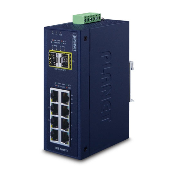
P2 FAULT 1000 100/1000X SFP 1000 10/100 IGS-1020TF Figure 2-1: IGS-1020TF Front Panel „ Gigabit TP Interface 10/100/1000BASE-T Copper, RJ45 Twisted-pair: Up to 100 meters. „ SFP Slot 100/1000BASE-X mini-GBIC slot, SFP (Small-form Factor Pluggable) transceiver module: From 550 meters to 2km (multi-mode fiber) and 10/20/30/40/50/70/120 kilometers (single-mode fiber). -
Page 6: Led Indicators
2.3 LED Indicators System Color Function Green Lit: indicates power 1 has power. Lit: indicates power 2 has power. Green Lit: indicates either power 1 or power 2 has FAULT no power. Per 10/100/1000T Port Color Function Lit: indicates the link through that port is successfully established at 100Mbps or 10Mbps. - Page 7 Per 100 / 1000X SFP Slot Color Function Lit: indicates the link through that port is successfully established at 100Mbps. Blinking: indicates that the Switch is Orange actively sending or receiving data LNK/ACT over that port. Off: indicates the link through that port is successfully established at 1000Mbps.
-
Page 8: Switch Upper Panel
2.4 Switch Upper Panel The upper panel of the Industrial Gigabit Ethernet Switch consists of one terminal block connector within two DC power inputs, Figure 2-2 shows the upper panel of the Industrial Gigabit Ethernet Switch. 1 2 3 4 5 6 V1+ V1- V2+ V2- Input... - Page 9 1. Insert positive and negative DC power wires into contacts 1 and 2 for POWER 1, or 5 and 6 for POWER 2. 1 2 3 4 5 6 V1+ V1- V2+ V2- Input PWR1 Fault PWR2 DC12~48V, AC 24V 2.
-
Page 10: Wiring The Fault Alarm Contact
1. The wire gauge for the terminal block should be in the range between 12 and 24 AWG. 2. Alarm relay circuit accepts up to 30V, max. 3A Note currents. 2.7 Product Specifications Model IGS-1020TF Hardware Specifications 8 x 10/100/1000BASE-T RJ45 TP Copper Ports Auto-MDI/MDI-X, auto-negotiation... - Page 11 2 1000BASE-SX/LX/BX SFP interfaces SFP/mini-GBIC (Port-9 and Port-10) Slots Compatible with 100BASE-FX SFP Switch Processing Store-and-Forward Scheme Switch Fabric 20Gbps (non-blocking) Switch Throughput (packet per 14.88Mpps@64bytes second) MAC Address Table 4K entries Back pressure for half duplex Flow Control IEEE 802.3x pause frame for full duplex Jumbo Frame 9216 bytes Removable 6-pin terminal block...
- Page 12 ESD Protection 6KV DC Enclosure IP30 type metal case Installation DIN rail kit and wall mount ear Dimensions 56 x 87 x 135 mm (W x D x H) Weight 540g DC 12~48V or AC 24V Power Redundant power with polarity reverses Requirements protection function Power...
- Page 13 Standards Conformance IEEE 802.3 Ethernet/10BASE-T IEEE 802.3u Fast Ethernet/100BASE-TX IEEE 802.3ab Gigabit Ethernet/1000BASE-T Standards IEEE 802.3z Gigabit Compliance Ethernet/1000BASE-SX/LX IEEE 802.3x Full-Duplex Flow Control IEEE 802.3az Energy Efficient Ethernet (EEE) IEEE 802.1p Cos Regulatory FCC Part 15 Class A, CE Compliance IEC60068-2-32 (free fall) Stability Testing IEC60068-2-27 (anti-shock) IEC60068-2-6 (anti-vibration)
-
Page 14: Installation
3. Installation This section describes the functionalities of the Industrial Gigabit Ethernet Switch’s components and guides how to install it on the DIN-rail and wall. Basic knowledge of networking is assumed. Please read this chapter completely before continuing. This following picture is telling the user how to install the device, and the device is not IGS- 1020TF. - Page 15 Step 2: Lightly insert the bottom of the switch into the track Step 3: Make sure if the DIN-Rail is tightly secured on the track. Step 4: Please refer to the following procedures to remove the Industrial Gigabit Ethernet Switch from the track.
-
Page 16: Wall-Mount Plate Mounting
Step 5: Lightly pull out the bottom of the switch for removing it from the track. 3.2 Wall-mount Plate Mounting To install the Industrial Gigabit Ethernet Switch on the wall, please follow the instructions described below. Step 1: To remove the DIN-Rail from the Industrial Gigabit Ethernet Switch, loosen the screws to remove the DIN-rail. -
Page 17: Installing The Sfp Transceiver
You can plug in and out the transceiver to/from any SFP port without having to power down the Industrial Gigabit Ethernet Switch as Figure 2-3 shows. MGB/MFB Series Module Figure 3-1: Plug-in the SFP Transceiver PLANET Industrial Gigabit Ethernet Switch supports 100/1000 dual mode with both single... - Page 18 4. Check the Link mode of the SFP port if the link fails. It is recommended to use PLANET SFPs on the Industrial Gigabit Ethernet Switch. If you insert an SFP transceiver that is not supported, the Indus- Note trial Gigabit Ethernet Switch will not recognize it.
-
Page 19: Removing The Transceiver Module
3.4 Removing the Transceiver Module 1. Make sure there is no network activity by consulting or checking with the network administrator. Or through the management interface of the switch/converter (if available) to disable the port in advance. 2. Remove the Fiber Optic Cable gently. 3. -
Page 20: Troubleshooting
4. Troubleshooting This chapter contains information to help you solve issues. If the Industrial Gigabit Ethernet Switch is not functioning properly, make sure the Industrial Gigabit Ethernet Switch was set up according to instructions in this manual. The per port LED is not lit Solution: Check the cable connection of the Industrial Gigabit Ethernet Switch. -
Page 21: Appendix A: Networking Connection
APPENDIX A: Networking Connection A.1 Switch’s RJ45 Pin Assignments 1000Mbps, 1000BASE-T Contact MDI-X BI_DA+ BI_DB+ BI_DA- BI_DB- BI_DB+ BI_DA+ BI_DC+ BI_DD+ BI_DC- BI_DD- BI_DB- BI_DA- BI_DD+ BI_DC+ BI_DD- BI_DC- 10/100Mbps, 10/100BASE-TX RJ45 Connector pin assignment MDI-X Contact Media Dependent Media Dependent Interface Interface -Cross Tx + (transmit) -
Page 22: Rj45 Cable Pin Assignments
A.2 RJ45 Cable Pin Assignments The standard RJ45 receptacle/connector There are 8 wires on a standard UTP/STP cable and each wire is color-coded. The following shows the pin allocation and color of straight-through cable and crossover cable connection: Straight Cable SIDE 1 SIDE 2 1 = White/Orange... -
Page 23: Fiber Optic Cable Connection Parameter
A.3 Fiber Optic Cable Connection Parameter The wiring details are shown below: 100FX Fiber Optic Cables: Standard Fiber Type Cable Specifications 100BASE-FX 50/125μm or Multi-mode (1300nm) 62.5/125μm 50/125μm or Multi-mode 100BASE-FX 62.5/125μm (1310nm) Single-mode 9/125μm 100BASE-BX-U Single-mode 9/125μm (TX:1310/RX:1550) 100BASE-BX-D (TX:1550/RX:1310) 1000X Fiber Optic Cables: Standard Fiber Type Cable Specifications... - Page 24 Wiring Distances: Modal Diameter Max. Distance Standard Fiber Bandwidth (micron) (meters) (MHz * km) 62.5 62.5 1000BASE- SX MM 62.5 1000BASE- LX 5000*...
-
Page 25: Appendix B: Approved Planet Sfp Transceivers
APPENDIX B: Approved PLANET SFP Transceivers The following list of approved PLANET SFP transceivers is correct at the time of publication: Gigabit SFP Transceiver Modules MGB-GT SFP-Port 1000BASE-T Module - 100m MGB-SX SFP-Port 1000BASE-SX mini-GBIC module - 550m MGB-SX2 SFP-Port 1000BASE-SX mini-GBIC module – 2km... - Page 26 SFP-Port 1000BASE-LX (WDM, TX:1310nm) mini- MGB-LA60 GBIC module - 60km SFP-Port 1000BASE-LX (WDM, TX:1550nm) mini- MGB-LB60 GBIC module - 60km SFP-Port 1000BASE-SX mini-GBIC module - 550m MGB-TSX (-40~75°C) SFP-Port 1000BASE-LX mini-GBIC module - 10km MGB-TLX (-40~75°C) SFP-Port 1000BASE-LX mini-GBIC module - 30km MGB-TL30 (-40~75°C) SFP-Port 1000BASE-LX mini-GBIC module - 70km...
- Page 27 Fast Ethernet SFP Transceiver Modules MFB-FX SFP-Port 100BASE-FX Transceiver (1310nm) - 2km SFP-Port 100BASE-FX Transceiver (1310nm) - MFB-F20 20km SFP-Port 100BASE-FX Transceiver (1310nm) - MFB-F40 40km SFP-Port 100BASE-FX Transceiver (1310nm) - MFB-F60 60km SFP-Port 100BASE-FX Transceiver (1550nm) - MFB-F120 120km SFP-Port 100BASE-BX Transceiver (WDM, MFB-FA20 TX:1310nm) - 20km...
Need help?
Do you have a question about the IGS-1020TF and is the answer not in the manual?
Questions and answers