
Related Manuals for Planet IGS-1020PTF Series


Summary of Contents for Planet IGS-1020PTF Series
- Page 1 Industrial 8-Port 10/100/1000T 802.3at PoE + 2-Port 100/1000X SFP Ethernet Switch IGS-1020PTF Series User’s Manual...
-
Page 2: Table Of Contents
Table of Contents 1. Package Contents ................. 3 2. Hardware Introduction ................4 2.1 Switch Front Panel ................. 4 2.2 LED Indicators ................6 2.3 Switch Upper Panel ................ 7 2.4 Wiring the Power Inputs ..............8 2.5 Wiring the Fault Alarm Contact ............9 2.6 Grounding the Device .............. -
Page 3: Package Contents
1. Package Contents Thank you for purchasing PLANET Industrial 8-port 10/100/1000T 802.3at PoE + 2-port 100/1000X SFP Ethernet Switch, IGS-1020PTF or IGS-1020PTF-12V. The hardware specifications of these models are shown below: 10/100/1000T 802.3at 100/1000X Power Input Model Name PoE+ RJ45 Ports SFP Slots Range IGS-1020PTF DC 48~54V IGS-1020PTF-12V DC 12~54V In the following sections, the term “Industrial PoE+ Switch”... -
Page 4: Hardware Introduction
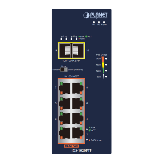
2. Hardware Introduction 2.1 Switch Front Panel The front panels of the Industrial PoE+ Switches consist of Ethernet interfaces and LED indicators as shown below: P1 P2 Alarm P1 P2 Alarm 1000 1000 PoE Usage PoE Usage 240W 240W 100/1000X SFP 100/1000X SFP 180W 180W Mode Mode Standard... - Page 5 In the “Extend” operation mode, Port 5 to Port 8 of the Industrial PoE+ Switch operate on a per-port basis at 10Mbps full duplex operation but can support 20~25-watt PoE power output over a distance of up to 250 meters overcoming the 100m limit on Ethernet UTP cable. With this feature, the Industrial PoE+ Switch provides an additional solution for 802.3af/at PoE+ distance extension.
-
Page 6: Led Indicators
After changing the DIP switch mode, please reboot the switch to take effect. 2.2 LED Indicators System Color Function Green Lights: Indicates power 1 has power. Green Lights: Indicates power 2 has power. Alarm Lights: Indicates either power 1 or power 2 has no power. Off: Indicates the PoE usage is less than 30W. Blinks: Indicates that the PoE usage is around 30W to Amber 59W. -
Page 7: Switch Upper Panel
Per 100/1000X SFP Slot (Port 9 to Port 10) Color Function Lights: Indicates the link through that port is successfully LNK/ established at 1000Mbps or 100Mbps. Green Blinks: Indicates that the switch is actively sending or receiving data over that port. Lights: Indicates the link through that port is successfully established at 1000Mbps. -
Page 8: Wiring The Power Inputs
2.4 Wiring the Power Inputs The 6-contact terminal block connector on the top panel of Industrial PoE+ Switch is used for two DC redundant power inputs. Please follow the steps below to insert the power wire. When performing any of the procedures like inserting the wires or tightening the wire-clamp screws, make sure the power is OFF to prevent from getting an electric shock. -
Page 9: Wiring The Fault Alarm Contact
1. The wire gauge for the terminal block should be in the range between 12 and 24 AWG. 2. The IGS-1020PTF-12V supports DC input range of 12V to 54V. To avoid damage, please use the IGS-1020PTF-12V under its specification. DC Input Max. PoE Budget 120W 240W 3. PWR1 and PWR2 must provide the same DC voltage while operating with dual power input. -
Page 10: Grounding The Device
1. The wire gauge for the terminal block should be in the range between 12 and 24 AWG. 2. Alarm relay circuit accepts up to 24V with a maximum current of 1A. 2.6 Grounding the Device Users MUST complete grounding wired with the device; otherwise, a sudden lightning could cause fatal damage to the device. Max. Fault Alarm Loading: 24V, 1A 1 2 3 4 5 6 DC Input: 48-54V... -
Page 11: Installation
3. Installation This section describes the functionalities of the Industrial PoE+ Switch’s components and guides you to installing it on the DIN-rail and wall. Basic knowledge of networking is assumed. Please read this chapter completely before continuing. installation procedures IGS-1020PTF IGS-1020PTF-12V are the same as those shown below. 3.1 DIN-rail Mounting Installation... -
Page 12: Wall-Mount Plate Mounting
3.2 Wall-mount Plate Mounting 3.3 Side Wall-mount Plate Mounting (for IGS-1020PTF only) -
Page 13: Product Specifications
4. Product Specifications Model IGS-1020PTF IGS-1020PTF-12V Hardware Specifications Hardware Version Copper Ports 8 10/100/1000BASET RJ45 auto-MDI/MDI-X ports 8 ports with 802.3at PoE+ injector function (Ports PoE Injector Ports 1 to 8) 2 1000BASE-SX/LX/BX SFP interfaces (Ports 9 to 10) SFP Slots Compatible with 100BASE-FX SFP Removable 6-pin terminal block Pin 1/2 for Power 1;... - Page 14 - Max. 5.6 - Max. 5.6 watts/19BTU@54V DC watts/19BTU@54V DC input (System) input (System) - Max. 7.28 - Max. 8.4 watts/24BTU@54V DC watts/29BTU@54V DC Power Consumption input (Ethernet Full input (Ethernet Full Loading) Loading) - Max. 265.1 - Max. 265.1 watts/904BTU@54V DC watts/904BTU@54V DC input (Ethernet + PoE input (Ethernet + PoE Full Full Loading) Loading) Dimensions...
- Page 15 Per port 48~54V DC Per port 54V DC PoE Power Output Max. 30 watts Max. 30 watts 240W maximum@54V DC PoE Power Budget 240W maximum 120W maximum@24V DC (max.) 60W maximum@12V DC Max. Number of Class 3 PDs@25W Standards Conformance Regulatory Compliance FCC Part 15 Class A, CE IEC 60068-2-32 (free fall) Stability Testing IEC 60068-2-27 (shock) IEC 60068-2-6 (vibration) IEEE 802.3 Ethernet IEEE 802.3u Fast Ethernet...
-
Page 16: Customer Support
Customer Support Thank you for purchasing PLANET products. You can browse our online FAQ resource at the PLANET Web site first to check if it could solve your issue. If you need more support information, please contact PLANET support team. - Page 17 FCC Warning This equipment has been tested and found to comply with the regulations for a Class A digital device, pursuant to Part 15 of the FCC Rules. These limits are designed to provide reasonable protection against harmful interference when the equipment is operated in a commercial environment. This equipment generates, uses, and can radiate radio frequency energy and, if not installed and used in accordance with this user’s guide, may cause harmful interference to radio communications.
Need help?
Do you have a question about the IGS-1020PTF Series and is the answer not in the manual?
Questions and answers