Table of Contents
Advertisement
Quick Links
Advertisement
Table of Contents

Related Manuals for Planet IGS-1000 Series


Summary of Contents for Planet IGS-1000 Series
- Page 1 Industrial Ethernet Switch IGS-1000 Series User’s Manual...
-
Page 2: Table Of Contents
Table of Contents 1. Package Contents ................. 3 2. Hardware Introduction ................5 2.1 Switch Front Panel ................. 5 2.2 LED Indicators ................6 2.3 Switch Upper Panel ................ 7 2.4 Wiring the Power Inputs ..............8 2.5 Wiring the Fault Alarm Contact ............. 10 2.6 Grounding the Device .............. -
Page 3: Package Contents
1. Package Contents Thank you for purchasing PLANET IGS-1000-8T4X and IGS-1000-8UP4X Industrial Ethernet Switches. The descriptions of this IGS-1000 series are as follows: Industrial 8-Port 10/100/1000T + 4-Port 10G SFP+ IGS-1000-8T4X Ethernet Switch (-40~75 degrees C) Industrial 8-Port 10/100/1000T 802.3bt PoE + 4-Port 10G... - Page 4 Technical Support: support@planet.com.tw Copyright © PLANET Technology Corp. 2024. Contents are subject to revision without prior notice. PLANET is a registered trademark of PLANET Technology Corp. All other trademarks belong to their respective owners. Part No. 2360-AH7080-000 DIN-rail Kit x 1...
-
Page 5: Hardware Introduction
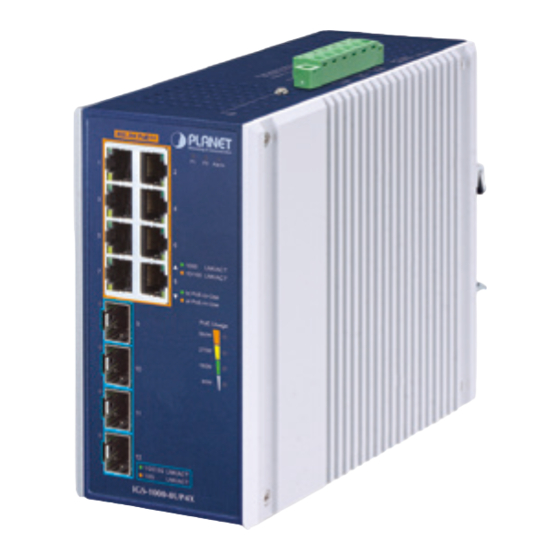
2. Hardware Introduction 2.1 Switch Front Panel The front panels of the Industrial Ethernet Switch series consist of Ethernet interfaces and LED indicators as shown below: 802.3bt PoE++ Alarm Alarm 1000 LNK/ACT 1000 LNK/ACT 10/100 LNK/ACT bt PoE-in-Use 10/100 LNK/ACT at PoE-in-Use PoE Usage 360W... -
Page 6: Led Indicators
Gigabit TP Interfaces (Port 1 to Port 8) Eight 10/100/1000BASE-T RJ45 copper interfaces come with 802.3bt PoE++ type 4 injector function (For IGS-1000-8UP4X) 10Gigabit SFP+ Slots (Port 9 to Port 12) Four 1G/2.5G/10GBASE-X SFP+ slots 2.2 LED Indicators IGS-1000-8T4X ... - Page 7 PoE Usage LED (For IGS-1000-8UP4X) Color Function Blinks: To indicate the system consumes close to 360-watt 360W Amber PoE power budget Lights: To indicate the system consumes over 270-watt 270W Amber PoE power budget Lights: To indicate the system consumes over 180-watt 180W Amber PoE power budget...
-
Page 8: Switch Upper Panel
10GBASE-X SFP+ Interfaces (Port 9 to Port 12) Color Function Lights: To indicate the port is running at 1000Mbps or 1G/2.5G 2500Mbps and successfully established. Green Blinks: To indicate that the switch is actively sending or LNK/ACT receiving data over that port. Lights: To indicate the port is running at 10Gbps and Amber LNK/ACT... -
Page 9: Wiring The Power Inputs
Figure 2-4 shows the upper panel of the IGS-1000-8UP4X. Dual power input is required for maximum PoE loading. Refer to user’s manual for more details. Max. Fault Alarm Loading: 24V, 1A 1 2 3 4 5 6 DC Input: 48-54V , 8A max. - Page 10 2. The IGS-1000-8T4X supports DC input range of 9V to 48V. The IGS-1000-8UP4X supports DC input range of 48V to 54V. To avoid damage, please use the IGS-1000 Series under its specification. PWR1 and PWR2 must provide the same DC voltage while...
-
Page 11: Wiring The Fault Alarm Contact
2.5 Wiring the Fault Alarm Contact The fault alarm contacts are in the middle of the terminal block connector as the picture shows below. Inserting the wires, the Industrial Ethernet Switch will detect the fault status of the power failure and then forms an open circuit. The following illustration shows an application example for wiring the fault alarm contacts. -
Page 12: Grounding The Device
2.6 Grounding the Device Users MUST complete grounding wired with the device; otherwise, a sudden lightning could cause fatal damage to the device. Max. Fault Alarm Loading: 24V, 1A 1 2 3 4 5 6 DC Input: 9-48V , 2A max. AC Input: 24V , 0.8A max. -
Page 13: Installation
3. Installation This section describes the functionalities of the Industrial Ethernet Switch’s components and guides you to installing it on the DIN-rail and wall. Basic knowledge of networking is assumed. Please read this chapter completely before continuing. The installation procedures of the IGS-1000-8T4X and IGS- 1000-8UP4X are the same as those shown below. -
Page 14: Wall-Mount Plate Mounting
3.2 Wall-mount Plate Mounting * The above pictures are for illustration only. You must use the screws supplied with the wall-mounting brackets. Damage caused to the parts by using incorrect screws would invalidate your warranty. -
Page 15: Product Specifications
4. Product Specifications Model IGS-1000-8T4X IGS-1000-8UP4X Hardware Specifications Copper Ports 8 10/100/1000BASET RJ45 auto-MDI/MDI-X ports PoE Injector 8 ports with 802.3bt PoE++ Ports injector function (Ports 1 to 8) 4 10GBASE-X SFP+ interfaces (Ports 9 to 12) SFP Slots Backward compatible with 1000BASE-X and 2500BASE-X SFP transceivers Removable 6-pin terminal block Pin 1/2 for Power 1... - Page 16 10/100/1000BASE-T 10/100/1000BASE-T RJ45 RJ45 Interfaces (Port 1 Interfaces (Port 1 to Port to Port 8): 1000Mbps LNK/ACT 1000Mbps LNK/ACT (Green) (Green) 10/100Mbps LNK/ACT (Amber) 10/100Mbps LNK/ACT 802.3bt PoE-in-Use (Green) (Amber) 802.3at PoE-in-Use (Amber) Per 1G/2.5G/10Gbps Per 1G/2.5G/10Gbps SFP Interfaces (Port 9 to Port LED Indicators Interfaces (Port 9 to 12):...
- Page 17 PoE Power Ports 1 to 8: 95 watts max. Output Pair 1 End-span: 1/2(-), 3/6(+) Power Pin Pair 2 Mid-span: 4/5(+), 7/8(-) Assignment 802.3bt: 1/2(-), 3/6(+), 4/5(+), 7/8(-) Single power input: 240W PoE Power maximum Budget (max.) Dual power input: 360W maximum Standards Conformance Regulatory...
-
Page 18: Customer Support
Customer Support Thank you for purchasing PLANET products. You can browse our online FAQ resource at the PLANET Web site first to check if it could solve your issue. If you need more support information, please contact PLANET support team. - Page 19 FCC Warning This device has been tested and found to comply with the limits for a Class A digital device, pursuant to Part 15 of the FCC Rules. These limits are designed to provide reasonable protection against harmful interference when the equipment is operated in a commercial environment.
Need help?
Do you have a question about the IGS-1000 Series and is the answer not in the manual?
Questions and answers