Visonic PowerMaster-30 G2 User Manual
Wireless alarm control system
Hide thumbs
Also See for PowerMaster-30 G2:
- Quick user manual (96 pages) ,
- Installer's manual (82 pages) ,
- User manual (78 pages)
Table of Contents
Advertisement
1. Introduction .................................................... 3
Preface ......................................................... 3
Overview ....................................................... 3
System Features ........................................... 3
Controls ........................................................ 4
LED Indicators .............................................. 4
Control Keys ................................................. 5
Arming Keys ................................................. 5
Other Keys .................................................... 5
Controls ........................................................ 5
LED Indicators .............................................. 6
Control Keys ................................................. 6
Arming Keys ................................................. 6
Other Keys .................................................... 6
Built-in Alarm Sounder .................................. 7
General Audible Indicators ............................ 7
Other Audible Indicators ............................... 7
LCD Display .................................................. 7
Screen Saver Mode ...................................... 8
Proximity Tags .............................................. 8
Users and Codes .......................................... 8
2. Operating the PowerMaster System ............. 9
Preparing to Arm ........................................... 9
Arming 'AWAY' / 'HOME' .............................. 9
Disarming and Stopping Alarm ..................... 9
Disarming under Duress ............................. 10
Partition Selection Process ......................... 10
Switching from 'HOME' to 'AWAY' .............. 10
Switching from 'AWAY' to 'HOME' .............. 10
Arming AWAY or HOME 'Instant' ................ 10
Forced Arming AWAY or HOME ................. 11
Arming in the Latchkey Mode ...................... 12
Initiating Panic Alarm .................................. 12
Chime ON/OFF ........................................... 13
of the Keypad Beeps................................... 13
D-307074 PowerMaster-10/30 G2 User's Guide
PowerMaster-10/30 G2
Version 19.4
User's Guide
Table of Contents
3. Speech and Sound Control .......................... 14
Speech & Sound Cont. Push-buttons .......... 14
Voice ON/OFF ............................................. 14
Message Exchange ..................................... 14
Message Playback ...................................... 15
4. Electrical Appliance Control ........................ 16
Control Options and Pushbuttons ................ 16
Automatic ON/OFF Control ......................... 16
Alarm & Tamper Memory Indication ............ 17
Clearing the Memory Indication ................... 17
Troubles ...................................................... 17
General Indications ..................................... 18
Correcting Trouble Situations ...................... 19
6. Menus and Functions ................................... 20
Selecting a Setting Option ........................... 20
the USER SETTINGS Menu ........................ 22
B.1 Setting the Zone Bypass Scheme ......... 22
B.3 Recalling the Zone Bypass Scheme ...... 24
B.4 Programming User Codes ..................... 25
B.5 Programming the Duress Code ............. 27
B.6 Add / Delete Proximity Tags .................. 27
B.7 Add / Delete Keyfob Transmitters ......... 29
B.8 Setting the Time & Time Format ........... 32
B.9 Setting the Date & Date Format ............ 33
B.10 Enabling / Disabling Auto-Arming ........ 34
B.11 Setting the Auto-Arming Time ............. 34
MMS and SMS Reporting ............................ 35
.................................................................... 42
B.14 Programming the Scheduler ................ 43
B.15 Volume Control ................................... 46
B.16 Serial Number ..................................... 49
B.17 PowerLink Parameters* ...................... 50
1
Advertisement
Table of Contents

Related Manuals for Visonic PowerMaster-30 G2


Summary of Contents for Visonic PowerMaster-30 G2
-
Page 1: Table Of Contents
Arming Keys ..........5 5. Reviewing Troubles and Alarm memory ..17 Other Keys ............ 5 Alarm & Tamper Memory Indication .... 17 PowerMaster-30 G2 Panel Indicator and Clearing the Memory Indication ....17 Controls ............5 Troubles ............17 LED Indicators .......... - Page 2 7. Event Reporting and Control by Telephone A2. KP-140/141 PG2 ........63 and SMS ............51 A3. KF-234 PG2 .......... 64 Event notifications by Telephone ....51 APPENDIX B. PARTITIONING ......65 Event notifications by SMS ......52 B1. Selecting a Partition ......65 Remote Control by Telephone ....
-
Page 3: Introduction
Master / User Settings: Two user levels allow different access types (see Chapter 6. Menus and Functions, section B.4 Programming User Codes). 30 detector zones (PowerMaster-10 G2) / 64 detector zones (PowerMaster-30 G2): Each detector zone is identified by zone number and name (location). -
Page 4: Powermaster-10 G2 Panel Indicator And Controls
INTRODUCTION Numerical keys serve as function keys: When the system is disarmed, the numerical keys are used also to control various system functions. A simple icon on each key identifies the task of that key. Data retrieval: You can obtain status information, trouble information and review memorized alarm events visually (see Chapter 5). -
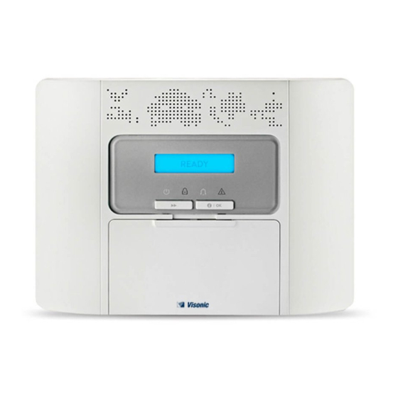
Page 5: Control Keys
Chime ON/OFF Reviewing the event log Emergency (hold for 2 sec.) Fire (hold for 2 sec.) Press both buttons simultaneously for panic alarm PowerMaster-30 G2 Panel Indicator and Controls Figure 1b. PowerMaster-30 G2 Controls and Indicators D-307074 PowerMaster-10/30 G2 User's Guide... -
Page 6: Led Indicators
PGM control PGM output OFF PGM output ON Volume up * Volume down * Record message * Play message * Mute speaker * / ** * May not be functional on all versions of PowerMaster-30 G2. D-307074 PowerMaster-10/30 G2 User's Guide... -
Page 7: Built-In Alarm Sounder
The normal display alternates with the time and the system status, for example: READY HH:MM (alternating) READY MEMORY Refers to PowerMaster-30 G2 with voice option only Refers to PowerMaster-30 G2 with voice option only D-307074 PowerMaster-10/30 G2 User's Guide... -
Page 8: Screen Saver Mode
(see Chapter 6, B.4 Programming User Codes). Moreover, you can obtain up to 8 (PowerMaster-10 G2) / 32 (PowerMaster-30 G2) multi-function portable keyfob transmitters that will allow you and the other users to easily arm, disarm and control the system without accessing the panel, including from outside the premises (see Chapters 2 and 6, B.7 Add / Delete Keyfob... -
Page 9: Operating The Powermaster System
For more information regarding terms used in this chapter, refer to APPENDIX C. GLOSSARY. Note: This manual displays PowerMaster-10 G2 panel buttons only, even when instructions refer to both panels. When an instruction refers to PowerMaster-30 G2 only, the PowerMaster-30 G2 panel buttons are displayed. Basic Arming and Disarming Following are a set of procedures for performing basic arming and disarming of the alarm system. -
Page 10: Disarming Under Duress
OPERATING THE POWERMASTER SYSTEM PRESS RESULTING DISPLAY PRESENT TAG OR ENTER CODE _ _ _ _ [Enter Code] / Code / Present gag [Present tag] READY HH:MM ARM indicator extinguishes during the disarmed state. Disarming the system also stops the siren alarm, irrespective of whether the alarm was initiated during the armed or the disarmed state. -
Page 11: Forced Arming Away Or Home
OPERATING THE POWERMASTER SYSTEM PRESS RESULTING DISPLAY PRESENT TAG OR ENTER CODE _ _ _ _ Code ARMING AWAY ARMING INSTANT (alternating) PLEASE EXIT NOW Vacate the premises (Exit delay) AWAY ARM indicator lights during the armed state. Forced Arming AWAY or HOME Forced arming allows you to arm the system even if the system is "NOT READY". -
Page 12: Arming In The Latchkey Mode
Latchkey users are holders of user codes or users of keyfob transmitters 5 through 8 (PowerMaster-10 G2) / 23- 32 (PowerMaster-30 G2). The latchkey message is considered an alert and not an alarm, and is therefore sent to the private telephones programmed by the user as targets for alert messages. -
Page 13: Chime On/Off
The following diagrams show how to increase or decrease the loudness by clicking the <1> or<4> key (assuming that the volume was at minimum/maximum to begin with). PRESS RESULTING DISPLAY PRESS RESULTING DISPLAY VOLUME+ VOLUME– (max) VOLUME+ VOLUME– VOLUME+ VOLUME– (max) VOLUME+ VOLUME– Refers to PowerMaster-30 G2 with voice option only D-307074 PowerMaster-10/30 G2 User's Guide... -
Page 14: Speech And Sound Control
RECORD A MESSAGE (constant) Talk TALK NOW Talk TALK NOW Talk TALK NOW Talk TALK NOW Talk TALK NOW RECORDING ENDED Stop talking Refers to PowerMaster-30 G2 with voice option only D-307074 PowerMaster-10/30 G2 User's Guide... -
Page 15: Message Playback
SPEECH AND SOUND CONTROL Once the last of the boxes disappears, RECORDING ENDED will be displayed. When you release the button, the display will revert to the normal status-displaying mode, but will also indicate that a message is waiting. For example: READY HH:MM (alternating) -
Page 16: Electrical Appliance Control
ELECTRICAL APPLIANCE CONTROL 4. Electrical Appliance Control Control Options and Pushbuttons The system allows manual or automatic remote control of a device connected to the PGM output. The user defines the ON and OFF times via the Scheduler (see Chapter 6 - B.14 Programming the Scheduler). The installer determines which zone sensors will switch the remote controlled appliances on and off. -
Page 17: Reviewing Troubles And Alarm Memory
TRBL message is displayed, as follows. READY HH:MM NOT READY HH:MM (alternating) (alternating) READY TRBL NOT READY TRBL or, if the system is not ready for arming When working from the PowerMaster-30 G2 control panel, the display will read "POWERMASTER-30" D-307074 PowerMaster-10/30 G2 User's Guide... -
Page 18: General Indications
This message appears at the end of all TRBL messages and immediately following the GSM signal strength indication if a SIM card is installed. When working from the PowerMaster-30 G2 control panel, the display will read "POWERMASTER-30" D-307074 PowerMaster-10/30 G2 User's Guide... -
Page 19: Correcting Trouble Situations
REVIEWING TROUBLES AND ALARM MEMORY Correcting Trouble Situations The trouble indications (illuminated TROUBLE indicator and flashing TRBL message) are cleared once you eliminate the cause of trouble. The table below describes the system faults and respective corrective actions. If you do not know how to correct a trouble situation, report it to your installer and seek his advice. Fault What it means 1-WAY... -
Page 20: Menus And Functions
Note: This manual displays PowerMaster-10 G2 control panel buttons only, even when instructions refer to both control panels. When an instruction refers to PowerMaster-30 G2 only, the PowerMaster-30 G2 control panel buttons are displayed. - Page 21 EVENT REPORTING & CONTROL BY TELEPHONE AND SMS C. User Settings Options Menu Click until the display reads the desired setting option and then press Use to set the Zone Bypass Scheme i.e. to bypass (exclude) faulty or unsecured SET ZONE BYPASS ("disturbed") zones, or to clear a bypassed zone (unbypass).
-
Page 22: Returning To The Previous Step Or Exiting The User Settings Menu
EVENT REPORTING & CONTROL BY TELEPHONE AND SMS A.2 Returning to the Previous Step or Exiting the USER SETTINGS Menu During the setting process it is frequently necessary to return to the previous setting step or option (i.e. "to go one level up") or to exit the User Settings menu. - Page 23 EVENT REPORTING & CONTROL BY TELEPHONE AND SMS 1. Zones will be bypassed throughout one disarm-arm period only. Disarming the system after arming will suspend the entire bypassing scheme but you can recall and reuse it as described in section B.3. 2.
-
Page 24: Reviewing The Zone Bypass Scheme
EVENT REPORTING & CONTROL BY TELEPHONE AND SMS B.2 Reviewing the Zone Bypass Scheme Here you can quickly review the Bypass Scheme i.e. the zones that are set to be bypassed during the next arming session. Enter the [USER SETTINGS] menu and select the [REVIEW BYPASS] REVIEW BYPASS option and press BYPASS LIST... -
Page 25: Programming User Codes
Each user out of the 8 (PowerMaster-10 G2) / 48 (PowerMaster-30 G2) system users can be authorized by the Master User to arm and disarm any combination of partitions including all 3 partitions. - Page 26 The display shows the 1 User Code (Master User) in the list of 8 User Codes (in PowerMaster-10 G2 system) / 48 User Codes (in PowerMaster-30 G2). If you have not yet changed the default code 1111, we recommend that you change it now.
-
Page 27: Programming The Duress Code
B.6 Add / Delete Proximity Tags A proximity tag may be assigned to each of the PowerMaster-10 G2 user codes 1-8 / PowerMaster-30 G2 user codes 1-32 that can be used instead of the user codes to perform a variety of functions, for example, arming, disarming, reading the event log, etc. - Page 28 EVENT REPORTING & CONTROL BY TELEPHONE AND SMS If enrollment was successfully completed, a "Success Tune" ☺ sounds and DEVICE ENROLLED the display reads [DEVICE ENROLLED] for a short duration and then ☺ Go to step 5 changes to read the tag's details. The display shows the allocated tag serial No (user No.), which is always the T01:Tag (Prox) first free number, for example: [T01:Tag (Prox)].
-
Page 29: Add / Delete Keyfob Transmitters
If the Partition option is enabled in the control panel, each of the 8 keyfobs (PowerMaster-10 G2) / 32 keyfobs (PowerMaster-30 G2) can be authorized by the Master User to arm and disarm any combination, or all 3 partitions, irrespective of the authorization of its corresponding user code. - Page 30 EVENT REPORTING & CONTROL BY TELEPHONE AND SMS the keyfob sticker and then press to confirm. To complete the enrollment procedure, see Note 9 in the Additional Information table below. ☺ ID ACCEPTED If a valid ID was entered, a "Success Tune" sounds and the display reads [ID ACCEPTED] for a short duration and then changes to read the ☺...
- Page 31 LED may blink for several seconds more while trying to establish communication. During this period of time the keyfob keys are disabled. The display shows the first enrolled Keyfob (Keyfob No.1) of the 8 keyfobs (PowerMaster-10 G2) / 32 keyfobs (PowerMaster-30 G2). To abort enrollment press the button.
-
Page 32: Setting The Time & Time Format
EVENT REPORTING & CONTROL BY TELEPHONE AND SMS B.8 Setting the Time & Time Format Here you can program or adjust the built-in-clock to show the correct time in the desired time format. You can select between a 24 hour and a 12 hour (AM/PM) time format. Carefully read the section titled "Additional Information"... -
Page 33: Setting The Date & Date Format
EVENT REPORTING & CONTROL BY TELEPHONE AND SMS B.9 Setting the Date & Date Format Here you can program or adjust the built-in-calendar to show the correct date in the desired date format. You can select between a "mm/dd/yyyy" and a "dd/mm/yyyy" date format. Carefully read the section titled "Additional Information"... -
Page 34: Enabling / Disabling Auto-Arming
EVENT REPORTING & CONTROL BY TELEPHONE AND SMS B.10 Enabling / Disabling Auto-Arming The PowerMaster system can be programmed to automatically arm itself on a daily basis at a predetermined time. This feature is useful especially in commercial applications, such as in stores, to ensure that the system is always armed and without having to assign security codes to employees. -
Page 35: Programming Private Phone, Email, Mms And Sms Reporting
A "Success Tune" sounds. The display confirms the set events to be alarms reported, and returns to step 3. 5, 15 ☺ Return to step 3 Refers to PowerMaster-30 G2 with voice option only D-307074 PowerMaster-10/30 G2 User's Guide... - Page 36 The display confirms the desired two-way disable two-way 5, 15 voice communication method and returns to step 15. ☺ Return to step 15 Refers to PowerMaster-30 G2 with voice option only D-307074 PowerMaster-10/30 G2 User's Guide...
- Page 37 EVENT REPORTING & CONTROL BY TELEPHONE AND SMS E. To Program the Acknowledge Method Voice<- ->private Click the button until the display reads [Tel. acknowledge] and press to confirm. Tel. acknowledge The display shows the currently selected option. by single ack Click the button until the display reads the desired acknowledge method, for example, "by all ack".
- Page 38 2nd E-MAIL Address When the display reads [Address], press To program or edit the email, at the blinking cursor position enter the Email, info@visonic.com for example, “info@visonic.com”, using the alphanumerical keypad. 6, 7 When done, press to confirm. ☺ info@visonic.com A "Success Tune"...
- Page 39 EVENT REPORTING & CONTROL BY TELEPHONE AND SMS MMS/SMS BY SERVER A. To Program Events to be Reported by SMS via the server Enter the [USER SETTINGS] menu, select the [PRIVATE REPORT] option PRIVATE REPORT and press VOICE REPORT When the display reads [VOICE REPORTS] press repeatedly until the display reads [SMS/MMS BY SRVR].
- Page 40 EVENT REPORTING & CONTROL BY TELEPHONE AND SMS The display shows the currently selected option. disable report Click the button until the display reads the event group you wish to be reported via MMS, for example, [alarm]. alarm When you are satisfied with the setting, press to confirm.
- Page 41 Arming and disarming (Open/close) only op/cl Note: “ ” means all events including the L. BAT and AC FAIL trouble messages (PowerMaster-30 G2 only). The display shows the currently selected option (indicated by a symbol), for example, "...
-
Page 42: Enabling / Disabling The Squawk Option
EVENT REPORTING & CONTROL BY TELEPHONE AND SMS Event Group Option Events to be reported No message will be reported disable report All messages Alarm messages only alarm Alarm and trouble messages alarm+trbl Alarm messages, including arming & disarming alarm+o/c Alarm and alert messages alarm+alrt Alarm, alert and trouble messages... -
Page 43: Programming The Scheduler
EVENT REPORTING & CONTROL BY TELEPHONE AND SMS symbol now appears next to the new selected option. You can now select another option in the User Settings menu (see section A.1 and section A.2), or quit programming (see section A.3). B.14 Programming the Scheduler PGM outputs that are enrolled in the system can be used to open and close an electrically-controlled gate, or to control a preferred electrical device via keyfobs (refer to "Using keyfob transmitters"... - Page 44 EVENT REPORTING & CONTROL BY TELEPHONE AND SMS E. To Set the OFF (Stop) Time Click the button until the display reads "Stop-HH:MM". Start-HH:MM Stop HH:MM When the display reads the desired setting, press to confirm. The "stop time" of the selected operation is displayed. TIME 01:30P Use the numerical keypad to set or change the operation OFF (stop) time, for...
- Page 45 EVENT REPORTING & CONTROL BY TELEPHONE AND SMS Device Device Operation 1 Operation 2 Operation 3 Operation 4 Description OFF: _ _: _ _ OFF: _ _: _ _ OFF: _ _: _ _ OFF: _ _: _ _ D-307074 PowerMaster-10/30 G2 User's Guide...
-
Page 46: Volume Control
EVENT REPORTING & CONTROL BY TELEPHONE AND SMS B.15 Volume Control The system allows you to adjust the volume level of the various system beeps, chime signal and voice prompts, and to enable or disable status dependent, pre-recorded verbal messages (Voice option) that are heard over the built-in loudspeaker. - Page 47 EVENT REPORTING & CONTROL BY TELEPHONE AND SMS C. To Adjust the Volume Level of the Exit Entry Beeps Click the button until the display reads [Exit Entry beeps], and press Exit/Entry beeps The display shows the currently selected option. ...
- Page 48 symbol now appears next to the newly selected option. Refers to PowerMaster-30 G2 with voice option only. If you have selected " ", make sure that the voice prompts can be heard over the...
-
Page 49: Serial Number
Displays the control panel serial number. 090703000 Displays the PowerMaster-10 G2 panel software version. JS702999 I19.412 Displays the PowerMaster-30 G2 panel software version. JS702999 K19.412 Displays the control panel keypad software version. JS700421 v1.0.02 Displays the control panel ID for PowerManage connectivity. -
Page 50: Powerlink Parameters
EVENT REPORTING & CONTROL BY TELEPHONE AND SMS B.17 PowerLink Parameters* The PLNK curr.params menu shows the current IP address, subnet mask, default gateway and current mode of communication. The PowerLink information is for support purposes only. Here you can see the current IP address of the PowerLink and other relevant data Carefully read the section titled "Additional information"... -
Page 51: Event Reporting And Control By Telephone And Sms
Arming AWAY, Arming HOME, Disarming No-activity, Emergency, Latchkey, Gas, Flood, Temperature Low-battery AC failure * PowerMaster-30 G2 only Note: For UL installations, SMS is a supplementary feature. PowerMaster-10 G2 control panels In case of alarm the following voice signal will be sent to private telephones upon event reporting: (- - - - - - FIRE: ON - ON - ON - pause.. -
Page 52: Event Notifications By Sms
EVENT REPORTING & CONTROL BY TELEPHONE AND SMS Event notifications by SMS Note: This feature is not to be not to be enabled in UL Listed product. The PowerMaster system when equipped with a GSM unit can be programmed to send SMS event notification messages to 4 pre-selected telephone numbers - see Chapter –... - Page 53 ] and then key your user code followed by the command (see “keying sequences” in Executable Commands table above). Refers to PowerMaster-30 G2 with voice option only Operates on all permitted partition(s) Refers to PowerMaster-30 G2 with voice option only...
-
Page 54: Remote Control By Sms
Note: The PowerMaster may react with a delay to received SMS messages if a GPRS session is in progress at the same time. Refers to PowerMaster-30 G2 only House ID includes up to 15 characters, for example, JOHN'S HOUSE D-307074 PowerMaster-10/30 G2 User's Guide... -
Page 55: Special Applications And Functions
SPECIAL APPLICATIONS AND FUNCTIONS 8. Special Applications and Functions Looking after People Left at Home In addition to acting as an alarm system, the PowerMaster can also be used to monitor the movement of people at home when the system is in the disarmed state (or even when armed “HOME” with perimeter protection only), and report lack of motion in interior zones if there is no detection of motion within predetermined time limits. -
Page 56: Testing The System
TESTING THE SYSTEM 9. Testing the System Periodic Test The components of your security system are designed to be maintenance-free as much as possible. Nevertheless, it is mandatory to test the system at least once a week and after an alarm event to verify that all system sirens, detectors, keyfobs, keypads and other peripherals function properly. - Page 57 TESTING THE SYSTEM TEMP/LIGHT TEST The display now reads [TEMP/LIGHT TEST]. To display the temperature of zones on the control panel, press The control panel reads the temperature and light intensity of each zone. The Z01 24.5C display alternates between the temperature, the light intensity, the sensor number and the sensor location.
-
Page 58: Periodic Test Per Partition
TESTING THE SYSTEM Smoke sensors: Perform a "Diagnostic test" as explained in the detector's datasheet. Keyfob: Activate any of the keyfob buttons. Keypads: Perform a disarm or arm routine or press any other key that activates the LED. Repeater: Follow the "Diagnostic Tests" described in the repeater's datasheet. Other devices: In general, follow the "Diagnostic Tests"... - Page 59 TESTING THE SYSTEM Contact sensor: Open or close the door or window protected by the contact. Motion sensors: Perform a "walk test" of the detector as explained in the detector's datasheet. Smoke sensors: Perform a "Diagnostic test" as explained in the detector's datasheet. Periodic test per partition will be interrupted (the panel returns to selected partition display) upon occurrence of one of the following: 1) Disarm event by keyfob, keypad or pendant assigned to a selected partition;...
-
Page 60: Maintenance
AC power and this trouble state continues for more than a few hours, the battery may need to be replaced. An original Visonic battery must be used of which there are a number of types. For assistance in battery replacement, contact Technical Support. -
Page 61: Exiting The Event Log
MAINTENANCE READY 00:00 ENTER CODE:_ When the PowerMaster display reads [ENTER CODE: _], enter the current CODE master user code. LIST OF EVENTS The "Success Tune" will sound and the PowerMaster display will read [LIST OF EVENTS]. (see Important Note!) Click the button. -
Page 62: Appendix A. Functions Of Controlling Devices
APPENDICES APPENDIX A. FUNCTIONS OF CONTROLLING DEVICES A1. KP-160 PG2 Arming and Disarming the System Step Operation User Actions Keyboard & Panel Response Select a PARTITION Any combination of The selected key blinks. (if Partition is enabled) Arm AWAY The selected key and the "Present Prox Tag"... - Page 63 APPENDICES A2. KP-140/141 PG2 Arming and Disarming the System Step Basic Arming User Actions Keypad & Panel Response Select a PARTITION The selected button lights. (Partition enabled) The selected button starts blinking Arm AWAY and prompts you to enter your "User Code"...
- Page 64 APPENDICES A3. KF-234 PG2 Keyfob Functionality Step Functions User Actions Response Arm AWAY When executing a command, the keyfob's LED blinks red once to indicate transmission of the command to Arm HOME the control panel. If the operation is successfully completed, the green LED lights momentarily and a Disarm (OFF) "Success tune"...
-
Page 65: Appendix B. Partitioning
APPENDICES APPENDIX B. PARTITIONING The control panel includes an optional partition feature. Partitioning is available only if your installer has enabled the feature. Once partitioning is enabled Partitioning menus are added to the system which can be viewed on the control panel's LCD display. Partitioning allows you to divide the system into three independently controllable areas with different users assigned to each partition whereby each user can arm the partition to which they are assigned. -
Page 66: B4. Siren
APPENDICES B4. Siren A partition is alarmed when receiving an event from an alarmed device assigned to that partition. Alarmed devices do not affect partitions to which they are not assigned. A siren is common to all partitions; therefore, an alarm from one or more partitions will activate the siren. - Page 67 APPENDICES Table A1 – Common Area Definitions Common area zone types Definition Perimeter Acts as defined only after the last assigned partition is armed AWAY or HOME. In case that one of the partitions is disarmed, an alarm initiated from this zone is ignored for all assigned partitions.
-
Page 68: Appendix C. Glossary
APPENDICES APPENDIX C. GLOSSARY This list of terms is arranged in alphabetical order. Abort Period: When an alarm is initiated, the internal built-in sounder is activated first for a limited period of time which is the abort period set by the installer. If you cause an alarm accidentally, you can disarm the system within the abort period before the real sirens start and before the alarm is reported to the remote responders. - Page 69 APPENDICES HOME: This type of arming is used when people are present within the protected site. A classic example is night-time at home, when the family is about to retire to bed. With HOME arming, perimeter zones are protected but interior zones are not. Consequently, motion within interior zones will be ignored by the control panel, but disturbance of a perimeter zone will cause an alarm.
-
Page 70: Appendix D. Home Fire Escape Planning
APPENDICES APPENDIX D. HOME FIRE ESCAPE PLANNING Fire can spread rapidly through your home, leaving you a short time to escape safely. Your ability to get out depends on advance warning from smoke detectors and advance planning – a home fire escape plan that everyone in your family is familiar with and has practiced. -
Page 71: Appendix E. Specifications
APPENDIX E. SPECIFICATIONS E1. Functional PowerMaster-10 G2 PowerMaster-30 G2 Zones Number 30 wireless zones (including 1 hard-wired Up to 64 wireless zones, (including 2 hard- input). wired inputs). Hard-wired Zone 2.2 kE.O.L. resistance (max. resistance of 2.2 kE.O.L. resistance (max. resistance of Requirements wires 220 ... -
Page 72: E2. Wireless
E2. Wireless PowerMaster-10 G2 PowerMaster-30 G2 RF Network PowerG – 2-way synchronized Frequency PowerG – 2-way synchronized Frequency Hopping (TDMA / FHSS) Hopping (TDMA / FHSS) Frequency bands 433 – 434 868 - 869 912 – 919* 433 – 434 868 - 869 912 –... - Page 73 450* mA max @ 12.5 VDC when powered by Current (INT) AC/DC (10.5 VDC when in standby mode) Total PowerMaster-30 G2 output current (of INT & EXT sirens, PGM output and detectors) cannot exceed 550 mA. Current sink to control panel GND 100 mA Current sink to control panel GND 100 mA max.
-
Page 74: E4. Communication
Report 2 Monitoring Stations, 4 private telephones 2 Monitoring Stations, 4 private telephones Destinations Reporting Format SIA, Contact ID, Scancom, SIA IP, Visonic SIA, Contact ID, Scancom, SIA IP, Visonic Options PowerNet. PowerNet. Note: For UL Listed product, the communication Note: For UL Listed product, the communication formats used are SIA and Contact ID. - Page 75 PowerMaster-10 G2 PowerMaster-30 G2 Shock: SD-304 PG2 (not UL listed) Shock: SD-304 PG2 (not UL listed) Note: UL requires that when using remote Note: UL requires that when using remote smoke/CO detectors and repeaters, each smoke/CO detectors and repeaters, each...
-
Page 76: Appendix F. Compliance With Standards
IC- RSS 210, ULC-C1023, ULC-S545-02 Note: Only devices operating at 912-919 MHz are tested and listed by UL/ULC. SIA CP01 standards: PowerMaster-10 G2 and PowerMaster-30 G2: for SIA CP01, a siren must be used in the system installation. GSM standards: Europe: Complies with CE standards: EN 301 511, EN301 489-7 USA: CFR 47 Part 22 (GSM850) and Part 24 (GSM 1900). - Page 77 This product is not to be thrown away with everyday waste. Directive 2002/96/EC Waste Electrical and Electronic Equipment. EMAIL: info@visonic.com INTERNET: www.visonic.com VISONIC LTD. 2017 POWERMASTER-10/30 G2 User's Guide D-307074 Rev 0 (09/17) D-307074 PowerMaster-10/30 G2 User's Guide...
Need help?
Do you have a question about the PowerMaster-30 G2 and is the answer not in the manual?
Questions and answers